EP1372242A2 - Méthode et appareil pour le bobinage de composants de machines dynamo-électriques - Google Patents
Méthode et appareil pour le bobinage de composants de machines dynamo-électriques Download PDFInfo
- Publication number
- EP1372242A2 EP1372242A2 EP03010672A EP03010672A EP1372242A2 EP 1372242 A2 EP1372242 A2 EP 1372242A2 EP 03010672 A EP03010672 A EP 03010672A EP 03010672 A EP03010672 A EP 03010672A EP 1372242 A2 EP1372242 A2 EP 1372242A2
- Authority
- EP
- European Patent Office
- Prior art keywords
- poles
- slot
- casing
- pockets
- wire coils
- Prior art date
- Legal status (The legal status is an assumption and is not a legal conclusion. Google has not performed a legal analysis and makes no representation as to the accuracy of the status listed.)
- Granted
Links
Images


Classifications
-
- H—ELECTRICITY
- H02—GENERATION; CONVERSION OR DISTRIBUTION OF ELECTRIC POWER
- H02K—DYNAMO-ELECTRIC MACHINES
- H02K15/00—Methods or apparatus specially adapted for manufacturing, assembling, maintaining or repairing of dynamo-electric machines
- H02K15/0056—Manufacturing winding connections
- H02K15/0068—Connecting winding sections; Forming leads; Connecting leads to terminals
-
- H—ELECTRICITY
- H02—GENERATION; CONVERSION OR DISTRIBUTION OF ELECTRIC POWER
- H02K—DYNAMO-ELECTRIC MACHINES
- H02K3/00—Details of windings
- H02K3/46—Fastening of windings on the stator or rotor structure
- H02K3/52—Fastening salient pole windings or connections thereto
- H02K3/521—Fastening salient pole windings or connections thereto applicable to stators only
- H02K3/522—Fastening salient pole windings or connections thereto applicable to stators only for generally annular cores with salient poles
-
- H—ELECTRICITY
- H02—GENERATION; CONVERSION OR DISTRIBUTION OF ELECTRIC POWER
- H02K—DYNAMO-ELECTRIC MACHINES
- H02K15/00—Methods or apparatus specially adapted for manufacturing, assembling, maintaining or repairing of dynamo-electric machines
- H02K15/04—Methods or apparatus specially adapted for manufacturing, assembling, maintaining or repairing of dynamo-electric machines of windings, prior to mounting into machines
- H02K15/0435—Wound windings
- H02K15/0442—Loop windings
-
- Y—GENERAL TAGGING OF NEW TECHNOLOGICAL DEVELOPMENTS; GENERAL TAGGING OF CROSS-SECTIONAL TECHNOLOGIES SPANNING OVER SEVERAL SECTIONS OF THE IPC; TECHNICAL SUBJECTS COVERED BY FORMER USPC CROSS-REFERENCE ART COLLECTIONS [XRACs] AND DIGESTS
- Y10—TECHNICAL SUBJECTS COVERED BY FORMER USPC
- Y10T—TECHNICAL SUBJECTS COVERED BY FORMER US CLASSIFICATION
- Y10T29/00—Metal working
- Y10T29/49—Method of mechanical manufacture
- Y10T29/49002—Electrical device making
- Y10T29/49009—Dynamoelectric machine
- Y10T29/49011—Commutator or slip ring assembly
-
- Y—GENERAL TAGGING OF NEW TECHNOLOGICAL DEVELOPMENTS; GENERAL TAGGING OF CROSS-SECTIONAL TECHNOLOGIES SPANNING OVER SEVERAL SECTIONS OF THE IPC; TECHNICAL SUBJECTS COVERED BY FORMER USPC CROSS-REFERENCE ART COLLECTIONS [XRACs] AND DIGESTS
- Y10—TECHNICAL SUBJECTS COVERED BY FORMER USPC
- Y10T—TECHNICAL SUBJECTS COVERED BY FORMER US CLASSIFICATION
- Y10T29/00—Metal working
- Y10T29/49—Method of mechanical manufacture
- Y10T29/49002—Electrical device making
- Y10T29/49009—Dynamoelectric machine
- Y10T29/49012—Rotor
-
- Y—GENERAL TAGGING OF NEW TECHNOLOGICAL DEVELOPMENTS; GENERAL TAGGING OF CROSS-SECTIONAL TECHNOLOGIES SPANNING OVER SEVERAL SECTIONS OF THE IPC; TECHNICAL SUBJECTS COVERED BY FORMER USPC CROSS-REFERENCE ART COLLECTIONS [XRACs] AND DIGESTS
- Y10—TECHNICAL SUBJECTS COVERED BY FORMER USPC
- Y10T—TECHNICAL SUBJECTS COVERED BY FORMER US CLASSIFICATION
- Y10T29/00—Metal working
- Y10T29/49—Method of mechanical manufacture
- Y10T29/49002—Electrical device making
- Y10T29/4902—Electromagnet, transformer or inductor
- Y10T29/49071—Electromagnet, transformer or inductor by winding or coiling
-
- Y—GENERAL TAGGING OF NEW TECHNOLOGICAL DEVELOPMENTS; GENERAL TAGGING OF CROSS-SECTIONAL TECHNOLOGIES SPANNING OVER SEVERAL SECTIONS OF THE IPC; TECHNICAL SUBJECTS COVERED BY FORMER USPC CROSS-REFERENCE ART COLLECTIONS [XRACs] AND DIGESTS
- Y10—TECHNICAL SUBJECTS COVERED BY FORMER USPC
- Y10T—TECHNICAL SUBJECTS COVERED BY FORMER US CLASSIFICATION
- Y10T29/00—Metal working
- Y10T29/49—Method of mechanical manufacture
- Y10T29/49002—Electrical device making
- Y10T29/4902—Electromagnet, transformer or inductor
- Y10T29/49073—Electromagnet, transformer or inductor by assembling coil and core
-
- Y—GENERAL TAGGING OF NEW TECHNOLOGICAL DEVELOPMENTS; GENERAL TAGGING OF CROSS-SECTIONAL TECHNOLOGIES SPANNING OVER SEVERAL SECTIONS OF THE IPC; TECHNICAL SUBJECTS COVERED BY FORMER USPC CROSS-REFERENCE ART COLLECTIONS [XRACs] AND DIGESTS
- Y10—TECHNICAL SUBJECTS COVERED BY FORMER USPC
- Y10T—TECHNICAL SUBJECTS COVERED BY FORMER US CLASSIFICATION
- Y10T29/00—Metal working
- Y10T29/53—Means to assemble or disassemble
- Y10T29/5313—Means to assemble electrical device
- Y10T29/53143—Motor or generator
- Y10T29/53152—Means to position insulation
-
- Y—GENERAL TAGGING OF NEW TECHNOLOGICAL DEVELOPMENTS; GENERAL TAGGING OF CROSS-SECTIONAL TECHNOLOGIES SPANNING OVER SEVERAL SECTIONS OF THE IPC; TECHNICAL SUBJECTS COVERED BY FORMER USPC CROSS-REFERENCE ART COLLECTIONS [XRACs] AND DIGESTS
- Y10—TECHNICAL SUBJECTS COVERED BY FORMER USPC
- Y10T—TECHNICAL SUBJECTS COVERED BY FORMER US CLASSIFICATION
- Y10T29/00—Metal working
- Y10T29/53—Means to assemble or disassemble
- Y10T29/5313—Means to assemble electrical device
- Y10T29/53143—Motor or generator
- Y10T29/53161—Motor or generator including deforming means
Definitions
- the present invention relates to improved wire coil designs for dynamo-electric machine components (e.g., stators for electric motors, generators, or alternators) and to manufacturing solutions for implementing such designs.
- dynamo-electric machine components e.g., stators for electric motors, generators, or alternators
- Dynamo-electric machines operate by exploiting the interaction of rotating magnetic fields with a magnetic part or rotor.
- ac electric motors include armatures or a configuration of insulated wire coils in a stationary part or stator. Current flow through the wire coils generates magnetic fields in the space of the stator.
- the wire coils are wound around ferromagnetic cores or poles to enhance the strength of the generated magnetic field.
- Stator casings made often made from ferromagnetic laminates. Longitudinal slots in the stator casings usually define these poles.
- the poles generally are tooth-like cross sections that are rectangular or trapezoidal, but are invariably provided with cap-like lateral extensions or shoes at their top ends to enhance the concentration or passage of magnetic flux.
- the operational characteristics of a dynamo-electric machine depend on the nature or properties of the generated magnetic field. These properties are determined by the particular structure or design of the slots, poles and the wire coils used. Design features such as the shape of the slots (e.g., depth, widths, and curvatures) and the winding specifications (e.g., wire size, turns, slot fill ratio) affect not only the performance and efficiency of the dynamo-electric machine, but are also relevant to dynamo-electric machine manufacturing costs and reliability.
- dynamo-electric machine components are designed for high slot fill conductivity.
- Conventional cap-like pole extensions are avoided, or optionally are installed after the wire coils are placed or inserted in the slots.
- the wide mouth-slot designs provide unhindered access to the interior portions of the slot. All regions or volumes of the slots are accessible for insertion or placement of wire coil turns. Thus greater slot fill conductivity can be achieved.
- the inventive wide-mouth slot design may, for example, be used to make compact, high current capacity poly-phase stators for automotive alternator applications.
- Wire coils corresponding to each of the current phases may, for example, be wave wound around the stator poles. Conventional wire sizes may be used for the wire turns of the wire coils. Optionally, thick bar conductors can be used for making a wire coil with a designed current-carrying capacity with fewer turns than is possible with smaller size wire.
- the wire coils can be formed using a nozzle to dispense stretches of wire conductors.
- the stator and the nozzle are moved relative to each other to place conductor lengths generally along the path or shape of the desired wire coil.
- Conductor lengths placed along the slot passages are then pulled or snapped into the slots by relative radial motion of the nozzle to insert the wire coil around the poles.
- the wire coil conductors may first be preformed or shaped on a co-axial mandrel.
- the mandrel can have seats to hold a pre-formed wire coil.
- the mandrel seats can be aligned with the stator passages. Radial push or presser mechanisms built, for example, into the mandrel seats, may be used to push transfer and press the pre-formed wire coil from the mandrel into the stator slots.
- parallel coil configurations in which individual coils are wound around individual pole
- the individual wire coils may be installed as preformed wire coils.
- the pre-formed wire coils may be made wound on (insulating material) pockets, and then transferred to surround the poles. In some cases the pocket carrying a pre-formed wire coil itself may be moved or transferred to surround a pole.
- a mandrel supports moveable pockets on a number of radial extensions. Flyer arms or other winding tools are used to pre-form wire coils in the supported pockets. The stator poles are then aligned with the radial mandrel extensions. Pockets holding the pre-formed wire coils on the radial mandrel extensions are then transferred on to the stator poles.
- One or more workstations may be used to concurrently process fractions of the number of wire coils required for a stator. Accordingly, the number of pockets/radial extensions on the mandrel in each of the workstations corresponds to a fraction of total the number of the poles. Processing a limited number of wire coils at a workstation may accommodate the workspace or clearance requirements of common winding tools (e.g., flyer arms) in otherwise tight stator geometries or configurations. In a convenient arrangement, each workstation is used to process wire-coils for the poles associated with a specific current phase. Thus for a three-phase stator, three workstations are used.
- Insulating covers may optionally be installed over the slot passages to mechanically retain the coil conductors in position.
- optional ferromagnetic pole extensions designed to enhance passage of magnetic flux through the poles can be installed after the wire coil has been inserted.
- stator 10 shown in FIG. 1.
- the casing of stator 10 may, for example, be assembled by conventional methods from shaped ferromagnetic laminates.
- Lamination slots e.g., slots 11, 12, 13, 14 running along the inner surface of the casing define the stator poles around which wire coils are formed.
- Stator 10 may have the phase and pole/slot configurations that are commonly used in stators for automobile alternator applications.
- stator 10 may have a three-phase, 36 slot configuration.
- each of the thirty-six stator slots is associated with a specific current phase.
- Adjacent slots are associated with the respectively adjacent current phases. This association progressively repeats itself in sequence around the stator (as the number of slots exceeds the number of different current phases).
- three intercalated sequences of slots are associated with the first, second and third current phases.
- Each sequence is 12 slots long and has a pitch or interval of three slots. For example, the sequence (1, 4, 7, ..., and 34) corresponds to the first phase, while the sequence (2, 5, 8, ..., and 35) corresponds to the second phase.
- Rotating magnetic fields are generated by flowing current of appropriate phase through wire coils placed in the slots.
- the wire coils may have different winding patterns (e.g., serial or parallel) around the stator poles.
- each wire coil corresponding to a current phase is wound or connected in series in a "wave configuration" (see e.g., FIG. 2) with longitudinal wire portions (e.g., portions 16a and 17a) running in the slots of the sequence associated with the current phase.
- longitudinal wire portions e.g., portions 16a and 17a
- Horizontal wire segments or lengths e.g., 16b and 17b
- These horizontal wire lengths are placed along the top or bottom axial faces of stator 10.
- each of the three current phases corresponds to a single wire coil around the stator. Thu, three-phase stator 10 has three wire coils.
- each of the stator wire coils may include several wire turns or filaments depending on the wire size used.
- Conventional manufacturing methods and apparatus for assembly of stators having a wave configuration of wire coils are disclosed, for example, in Barrera U.S. patent 4,512,376, and in Cardini et al. U.S. patent 5,845,392. It will, however, be understood that the invention disclosed herein is not limited to stators with wave wound coils, but is also applicable to other types of dynamo-electric machine components and to other types of winding configurations or patterns.
- one or more thick bar conductors are used to make the stator wire coils.
- the use of thick bar conductors may avoid the limitations associated with the conventional use of small size wires to make the stator coils.
- the use of thick bar conductors may simplify wire coil manufacture by reducing the number of wire turns required to fabricate a wire coil with a desired current-carrying capacity.
- the use of thick bar conductors may advantageously increase the conducting fill of the stator slots. High conducting fills may improve stator performance characteristics, and allow the construction of more compact stators than may be possible using coils made with smaller wire size. Compact stators may be preferred, for example, for automobile alternators.
- the first phase coil may be made from two thick bar conductors 16 and 17 that have diameters comparable to the width (W) of stator slot passages P.
- FIG. 1 shows longitudinal conductor portions 16a and 17a of the first phase coil that are respectively designated for placement in slots 11 and 14. Similar longitudinal conductor portions are designated for placement in other slots around the stator that are associated with the first current phase (not shown).
- FIG. 1 also shows phantom representations of conductor lengths 16b and 17b. These conductor lengths connect longitudinal conductor portions 16a and 17a to provide electrical continuity to the first phase coil around the stator. Conductor lengths 16b and 17b are designated to run across the top axial face 10' of stator 10.
- Stator 10 poles are suitably designed to accommodate insertion of the thick bar conductors in the stator slots.
- stator 10 poles are designed to increase the width (W) of the openings leading to slot passages P.
- the conventionally used cap-like pole expansion portions or shoes are omitted or reduced from the laminate casing that is used in stator 10.
- FIG. 1 shows, for example, stator 10 poles with reduced expansion portions (corners C). With the reduced or omitted pole expansion portions, the slot opening widths W are about the same as the general widths of slot passages P over their entire depths. These unconventionally enlarged slot opening widths W allow unrestricted insertion of coil wires or all sizes including thick bar conductors into the stator slots.
- the longitudinal slots in stator 10 are shown, as having a U-shape with approximately parallel pole sides (e.g., FIG. 6 sides 62 and 62'). It will be understood that the specific shape is chosen only for purposes of illustration herein. Other suitable shapes including those having variously tapered or curved sides may be used as appropriate or desired, for example, for specific pole designs or characteristics.
- Insulation inserts 15 line the walls of slot passages P to electrically isolate the conductors inserted in the stator slots. Inserts 15 may be made, for example, from plastic sheeting. Inserts 15 may be provided with axial end flanges or shoulder enlargements 15' (shown in phantom representation).
- pins 40 may be used to temporarily tack or hold inserts 15 in position in the stator slots. Pins 40 are removed prior to insertion of conductors (e.g., conductors 16a or 17a) in the stator slots. To facilitate this, suitable pin holding and withdrawing structures may be conveniently disposed adjacent to one or both ends of stator 10 in the stator assembly processes (not shown).
- stator 10 The assembly processes for making stator 10, may involve the use of a coil-form or mandrel 20.
- the stator wire coils are first formed on mandrel 20 in a wave configuration, and then transferred into stator 10.
- Mandrel 20 has seats 21 with radial passages P1 that are open toward the outer surface of mandrel 20.
- Mandrel 20 fits in the bore of stator 10 such that radial passages P1 can be aligned with slot passages P.
- Seats 21 are designed to receive longitudinal conductor portions of the wire coil (e.g., portions 16a and 17a).
- the axial ends of mandrel 20 are designed to receive conductor lengths (e.g., lengths 16b and 17b), which connect the longitudinal portions of the wire coil.
- Mandrel 20 includes suitable mechanisms to transfer out wire coils formed on it.
- mandrel 20 may include pressers 22 that move in radial direction R to push out longitudinal conductor portions of the wire coil placed or formed in seats 21.
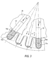
- a wire coil is first formed on mandrel 20 while mandrel 20 is outside the bore of stator 10 and the mandrel surface are readily accessible. Then mandrel 20 is inserted in the bore of stator 10 (as shown in FIG. 1) so that radial passages P1 are aligned with stator slot passages P. Next, pressers 22 are the operated to push longitudinal conductor portions (e.g., 16a and 17a) radially out of seats 21 into the aligned stator slot passages P. This push transfer of the longitudinal conductor portions in radial direction R also moves the connecting conductor lengths (e.g., lengths 16b and 17b) from the axial ends of mandrel 20 onto the axial ends of stator 10.
- FIG. 3 shows, for example, a wire coil that has been transferred from mandrel 20 into stator 10.
- wave wound wire coils can be formed in stator 10 by dispensing conductors directly into or along stator slot passages P.
- a delivery nozzle may be used to deliver or dispense the conductors.
- Suitable conventional drive mechanisms (not shown) may be used to provide the nozzle and/or stator 10 with the capability to move relative to each other. The drive mechanisms may allow relative motion, sequentially or simultaneously, in one or more dimensions.
- FIGS. 4 and 5 show, for example, a movable delivery nozzle 30 that can be used to dispense a conductor (e.g., conductor 16 or 17) along the stator slot passages P. Nozzle 30 operates through the bore and around stator 10.
- FIGS. 4 and 5 exemplify the linear movements of nozzle 30.
- FIG. 4 shows nozzle 30 at position PO1 after it has moved in upward direction 32 to dispense a stretch of longitudinal conductor portion 16a along or parallel to slot 11. Further movement of nozzle 30 in radial direction 33 to position PO2 (FIG. 5) pulls or inserts the dispensed stretch of longitudinal conductor portion 16a into slot 11.
- FIG. 5 also exemplifies the subsequent circular movement of nozzle 30 in an arc 35 along the axial face of stator 10 to deposit the conductor lengths (e.g., lengths 16b) that lead to the next longitudinal portion 16a of the wire coil (slot 14).
- nozzle 30 may be kept stationary as it dispenses the conductor lengths while stator 10 is rotated or indexed to the next slot.
- Optional guide forms may be employed to assist in mechanically shaping or bending the conductor lengths dispensed by nozzle 30.
- FIGS. 4 and 5 show, for example, guide forms 36 that are aligned with the end faces of stator 10.
- Guide forms 36 are suitably shaped to assist in bending the dispensed conductor so that conductor lengths (e.g., lengths 16b) stay close to the stator axial faces.
- the circular motion of nozzle 30 along arc 35 extends from position PO2 to a radially inward position PO3 above slot 14 in preparation for dispensing the next stretch of longitudinal conductor portion 16a.
- nozzle 30 can be used to insert a complete wave wound coil 16 in stator 10 by using suitable combinations of nozzle movements relative to stator 10 that are similar to those described above. For example, as a next step nozzle 30 can move downward from position PO3 (in a manner similar but opposite to its upward movement in direction 32) to dispense the next stretch of longitudinal conductor portion 16a for insertion in slot 14.
- nozzle 30 may also be used to dispense conductor 17 or any other number of different conductors that may be used to form the stator wire coils. Alternatively, separate or additional nozzles that are similar to nozzle 30 may be used to dispense conductor 17.
- the nozzles e.g., nozzle 30
- the nozzles may be rotatably mounted on arms or structures that allow continuous adjustment of the nozzle orientation. During the winding or dispensing of the wire coils, the nozzle orientation may be advantageously adjusted as needed so that at all times the dispensed conductor is ejected straight along the nozzle axis.
- suitable covers may be placed over the stator slots to mechanically retain the wire coil conductors in position.
- the covers may include suitable ferromagnetic material sections that enhance passage of magnetic flux through the poles of stator 10.
- FIG. 6 shows an exemplary slot cover 60 covering the stator slot between adjacent poles 63 and 64.
- Cover 60 is shaped so that it can be installed along the length of the stator slot and held against respective pole sides 62 and 62'.
- Stator 10 poles also may be designed to include optional seats running along the lengths of the poles to receive and hold cover 60 by its ends.
- FIG. 6 shows, for example, seats 65 and 66 running just below the edges or corners C of poles 63 and 64.
- Cover 60 includes an insulating portion 61 with lateral extensions or portions 60' and 60'', which may be made of suitable ferromagnetic material. When installed ferromagnetic lateral portions 60' and 60" provide additional magnetic conducting paths to increase the passage of magnetic flux through poles 63 and 64. Lateral portions 60' and 60'' may have widths X and other dimensions or shapes that are designed to replicate or otherwise function as the conventional pole shoe extensions that are omitted in stator 10 design to accommodate insertion of the thick bar conductors in the stator slots.
- slot covers 60 are installed by running the appendixes or edges of lateral portion 60' and 60" lengthwise through seats 65 and 66, until central portion 61 fully covers slot passage P.
- FIGS. 7 and 8 show an alternative slot cover arrangement that avoids the use or need for pole seats (such as seats 65 and 66) to hold slot covers in position.
- Slot covers 70 like covers 60, include insulating central portions 61 with ferromagnetic lateral extensions 60' and 60". Covers 70 are designed to lie over the stator slots between or abutting the edges or corners C of the adjoining stator poles. Covers 70 that are installed over the stator slots may be fixed in position by mechanically holding the longitudinal ends of covers 70. One or more rings that can be secured to the axial faces of stator 10 may, for example, be used to hold the ends of covers 70.
- FIG. 8 shows an exemplary arrangement of a pair of annular rings 71 and 72 that may be used for this purpose. In this arrangement, covers 70 extend as downward slats from upper annular ring 71.
- Lower annular ring 72 includes seats 72' that are designed to receive and hold longitudinal ends or feet 70' of the downward slats.
- Seats 72' and feet 70' may be mutually shaped, for example, as conventional tongue and groove joints, for mechanical rigidity of the slot cover arrangement.
- slot covers 70 are installed, for example, by placing lower annular ring 72 on an axial face of stator 10 with seats 72' aligned with stator slot passages P. Annular ring 71 is lowered over the opposing axial face such that covers 70 are inserted into the stator bore in alignment with the stator slot passages P and toward annular ring 72. Covers 70 are advanced sufficiently through the bore of stator 10 to allow cover feet 70' to extend into seats 72' of annular ring 72. Annular rings 71 and 72 are then be secured to the respective axial faces of stator 10 to hold covers 70 in fixed positions.
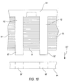
- FIGS. 9 and 10 Another slot cover arrangement, which may be used with suitably modified stator 10 structures, is shown in FIGS. 9 and 10.
- a cylindrical sheet 90 is used to cover the entire inner surface of the bore of stator 10.
- Cylindrical sheet 90 is made of alternating longitudinal sections may be similar to annular ring 71). These alternating sections include metal sections 91 that serve as pole expansions or shoes, and insulating sections 92 that function as slot covers. Insulating sections 92 may extend away from annular ring 93 to section ends or feet 92'. Feet 92' are designed for receipt and holding in seats 94' of a lower annular ring 94 that may be similar to annular ring 72 (FIG. 8).
- Metal sections 91 can be made from suitable ferromagnetic material in the form of a solid body. Alternatively, metal sections 91 may be made as a laminate. For example, metal sections 91 may be fabricated by stacking lamination sheets, one on top of the other. Conventional joining techniques may then be used to join the stack and form the laminate. Insulating sections 92 may be made from common insulation material, e.g., plastic material. Annular ring 93 also may be made of suitable plastic materials. Conventional plastic injection molding techniques may be used to fabricate insulating section 92 and annular ring 93 portions of cylinder sheet 90. These techniques may also be convenient for embedding metal sections 91 in cylinder sheet 90 between alternating insulating sections 92.
- annular ring 93 In the deployment of cylindrical sheet 90, upper annular ring 93 is suspended or held over an axial face of stator 10 so that insulating sections 92 and metal sections 91 extend downward in longitudinal direction 92". Cylindrical sheet 90 is lowered into the bore of stator 10 so that insulating sections 91 are aligned with slot passages P and the metal sections 92 are in contact with top surfaces of the stator poles (e.g., poles 63 and 64). For mechanical stability of deployed cylindrical sheet 90, ends or feet 92' of insulating sections 91 extending away from annular ring 93 may be mechanically supported at the opposing axial face of stator 10.
- Lower annular ring 94 with seats 94' which are designed to receive and hold feet 92', may be used for this purpose in a manner similar to that described above for slot covers 70 with reference to FIGS. 7 and 8.
- Annular rings 93 and 94 may be secured to the axial faces of stator 10 to mechanically fix the positions of insulating sections 92 over the stator slot passages P.
- the upper and lower ends of laminated metal sections 91 also may be point welded to the axial ends of the stator 10.
- the mutually contacting surfaces of metals sections 91 and stator poles may be designed to enhance the mechanical rigidity of deployed sheet 90.
- metal sections 91 may be provided with bottom curved contact surfaces 91', and the design of stator 10 may be suitably modified so that top surfaces (e.g., surfaces 63' and 64') of stator poles have curved shapes conforming to curved surfaces 91'. The conforming curvature of these surfaces allows good mechanical contact between the poles and metal sections 91, and yet restricts undesirable sliding movement of metal sections 91.
- This contact arrangement also provides electromagnetic conducting paths for the flow of magnetic flux from the stator poles into the metal 91.
- Metal sections 91 may be suitably shaped to enhance or optimize the flow of magnetic flux into the stator bore.
- Suitably shaped metal sections 91 may, for example, as shown in FIG. 9, have the shape of conventional pole expansions or shoes.
- slot covers In some stator designs, installation of slot covers to restrain wire coil conductors may not be suitable or required, or may be optional. Accordingly, the slot covers above can be suitably modified.
- the suitable modification may, for example, eliminate or limit the insulating sections (e.g., 61 or 91) and include only the pole extension sections (e.g., 60' and 60'', or 92).
- the slot covers may be designed to function primarily as pole extensions that can be attached to poles after insertion or formation of the wire coils around them.
- the slot covers may be designed to function primarily as insulating covers limiting or eliminating the pole extension function.
- the wide-mouth slot designs and the later-attachable pole extensions of the present invention provide greater design flexibility in dynamo-electric machine manufacture.
- the wide mouth slot designs may advantageously be used in other stator designs that, for example, call for parallel coils or small diameter wire coils (unlike the wave wound thick conductor coils of stator 10).
- the wide- or open-mouth slot design allows insertion of wire turns into all regions or portions of the slot volume without geometrical interference from the pole extensions. Thus higher slot conductivities can be achieved.
- FIGS. 11-14 illustrate the beneficial use of open-mouth slot designs in making stators (e.g., stator 170) with parallel coil configurations (i.e., in which individual coils are wound around individual poles).
- the individual coils may, for example, be pre-formed on a mandrel and then transferred or inserted radially into the slot passages before pole extensions are attached to the poles.
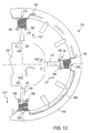
- Exemplary mandrel 100 may be used to pre-form wire coils supported on pockets 120 for insertion or transfer into stator 170.
- Mandrel 100 has a number of radial structures or extensions 110 on which hollow coil support pockets 120 are slidably mounted. Pockets 120 are designed to fit on both extensions 110 and on poles 20 of stator 170. Pockets 120 have trunk portions 120b between a pair of flanges 120a. Central hollows or passages 120c pass through pockets 120.
- pockets 120 When pockets 120 are supported on mandrel 1100, lengths of extensions 110 extending from shoulders 110'' pass through central passages 120c of pockets 120.
- the sliding position of pockets 120 on structures 110 may be limited at one end by flanges 120a acting against shoulders 110''.
- Suitable mechanical catches e.g., similar to catches 210) may be used to secure pockets 120 in position.
- Flanges 120a at the top end of poles 20 may be designed and made of suitable ferromagnetic material to serve as pole extensions.
- Flanges 120a at the top end include catches 210 that are designed to engage matching recesses on stator end board 170' to hold pockets 120 in position when they are fitted on poles 20.
- the number of pockets 120 may correspond to the number of wire coils (or poles) corresponding to a specific phase in stator 170.
- Mandrel 100 is designed so that the radial axes R through structures 110/pockets 120 can be with aligned with stator radii through poles 20.
- Individual wire coils 130 may be wound turn by turn, and layer by layer, on trunk portions 120b using, for example, a conventional flyer arm 140.
- Flyer 140 can rotate around axis R through a subject pocket 120 to deposit or pull wire turns W1 around trunk portions 120b. Flyer 140 may translate along axis R to stratify wire turns W1.
- Flanges 120a act as barriers, which limit the spread of wire turns W1 and coil layers along trunk portions 120b, and thus define the edges of the wound coils.
- Mandrel 100 may be indexed relative to flyer arm 140 to present pockets 120 in sequence for wire coil winding.
- Wire coils may be wound by flyer arm 140 successively on all pockets 120.
- more than one flyer arm like flyer arm 140 may be used to simultaneously wind wire coils around more than one of pockets 120.
- pockets 120 may be rotatable. Such rotatable pockets (120) may be rotated using suitable conventional drive mechanisms. Pockets 120 may be rotated to draw wire turns around themselves.
- a wire dispenser that can translate along axis R may be used may be used to stratify the wire turns drawn by rotating pocket 120.
- the wire winding configurations may be limited in some instances with consideration to stator size, and requirements of tool clearance and free operating space.
- three separate workstations may be used to concurrently process the individual coil sets corresponding to each of the three current phases.
- each workstation includes one mandrel.
- the number of extensions 110 provided on each mandrel 100 may be limited and equal the number of poles corresponding to single phase (e.g., 4 for the 12-pole stator 170 shown in FIG. 12). Limiting the number of extensions in this manner on the mandrels may provide adequate clearance for conventional tool (e.g., flyer arm) operation.
- wire coil leads 150 and 160 may be temporarily anchored to tabs or anchor posts on the body or the axial faces of mandrel 100, or optionally on flange 120a.
- Conventional lead manipulators may be used to manipulate leads 150 and 160 for this purpose (not shown).
- the lead manipulators used may be similar to those shown, for example, in coassigned and co-owned Luciani et al. U.S. patent 5,065,503.
- Such or other lead manipulators may be used to attach initial and final leads 15, and also uninterrupted leads 16 that connect the individual wire coils in a sequence associated with a single current phase.
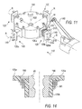
- mandrel 100 After all of the desired individual wire coils corresponding to single current phase have been pre-formed on mandrel 100 (See e.g., FIG. 12) they may be transferred onto stator poles 20 of stator 170. To initiate this transfer, mandrel 100 is inserted in the bore of stator 170. Pockets 120/extensions 110 are radially aligned with poles 20 as shown in FIG. 12. Next, pockets 120 are slid in direction 110'' from extensions 110 on to aligned poles 20. Suitable mechanisms may be used to slide pockets 120 from extensions 110 onto aligned poles 120. For example, moveable forks 180 may be used to engage and push flanges 120a in directions 110'' so that pockets 120 slid onto poles 20. Pockets 120 bearing the wire coils can slide on to poles 20 smoothly, for example, without geometrically interference from conventional pole extensions or other structures. Suitable pole extensions may be attached later if desired.
- FIG. 13 shows, for example, pockets 120 that have been transferred onto poles 20. Mechanical catches 210 engage the matching recesses 210' to secure pockets 120 in position over poles 20.
- FIG. 13 also shows leads 150 and 160 that have been repositioned from their temporary positions to stator end board 170' using suitable lead manipulators (e.g., the previously mentioned conventional lead manipulators). After installation of pockets 120 or a set of poles 20 corresponding to a single current phase, stator 170 may be transferred to the next workstation for installation of pockets 120 on the next set of poles.
- suitable lead manipulators e.g., the previously mentioned conventional lead manipulators
- Wire coils having high slot fill densities can be transferred on to poles 20.
- suitable pole extensions e.g., metal sections 92
- poles 20 may optionally be attached to poles 20.
- FIG. 14 shows an enlarged view of area 40 of FIG. 13 illustrating the fill of wire turns W1 in the corners of the pocket 120 adjoining pole 20.
- FIG. 14 also shows optional ferromagnetic inserts 190. Inserts 190, are placed in seats or built into flange 120a that may be made from insulating plastics. Inserts 190 abut the top ends of poles 20 and may be designed to function as pole extensions to enhance and distribute magnetic flux through poles 20.
Landscapes
- Engineering & Computer Science (AREA)
- Power Engineering (AREA)
- Manufacturing & Machinery (AREA)
- Manufacture Of Motors, Generators (AREA)
- Windings For Motors And Generators (AREA)
Priority Applications (2)
| Application Number | Priority Date | Filing Date | Title |
|---|---|---|---|
| SI200331677T SI1372242T1 (sl) | 2002-05-14 | 2003-05-13 | Postopek navijanja komponent dinamo-električnega stroja |
| EP09008597A EP2120316B1 (fr) | 2002-05-14 | 2003-05-13 | Méthode et appareil pour le bobinage de composants de machines dynamo-électriques |
Applications Claiming Priority (7)
| Application Number | Priority Date | Filing Date | Title |
|---|---|---|---|
| 1997-12-18 | |||
| US38089302P | 2002-05-14 | 2002-05-14 | |
| US380893P | 2002-05-14 | ||
| US39640602P | 2002-07-15 | 2002-07-15 | |
| US396406P | 2002-07-15 | ||
| US434892 | 2003-05-08 | ||
| US10/434,892 US20040046476A1 (en) | 2002-05-14 | 2003-05-08 | Dynamo-electric machine component winding methods and apparatus |
Related Child Applications (1)
| Application Number | Title | Priority Date | Filing Date |
|---|---|---|---|
| EP09008597A Division EP2120316B1 (fr) | 2002-05-14 | 2003-05-13 | Méthode et appareil pour le bobinage de composants de machines dynamo-électriques |
Publications (3)
| Publication Number | Publication Date |
|---|---|
| EP1372242A2 true EP1372242A2 (fr) | 2003-12-17 |
| EP1372242A3 EP1372242A3 (fr) | 2005-11-09 |
| EP1372242B1 EP1372242B1 (fr) | 2009-07-08 |
Family
ID=29587682
Family Applications (2)
| Application Number | Title | Priority Date | Filing Date |
|---|---|---|---|
| EP03010672A Expired - Lifetime EP1372242B1 (fr) | 2002-05-14 | 2003-05-13 | Méthode pour le bobinage de composants de machines dynamo-électriques |
| EP09008597A Expired - Lifetime EP2120316B1 (fr) | 2002-05-14 | 2003-05-13 | Méthode et appareil pour le bobinage de composants de machines dynamo-électriques |
Family Applications After (1)
| Application Number | Title | Priority Date | Filing Date |
|---|---|---|---|
| EP09008597A Expired - Lifetime EP2120316B1 (fr) | 2002-05-14 | 2003-05-13 | Méthode et appareil pour le bobinage de composants de machines dynamo-électriques |
Country Status (8)
| Country | Link |
|---|---|
| US (5) | US20040046476A1 (fr) |
| EP (2) | EP1372242B1 (fr) |
| AT (2) | ATE525787T1 (fr) |
| CA (1) | CA2428685A1 (fr) |
| DE (1) | DE60328245D1 (fr) |
| DK (1) | DK1372242T3 (fr) |
| ES (1) | ES2329024T3 (fr) |
| SI (1) | SI1372242T1 (fr) |
Cited By (15)
| Publication number | Priority date | Publication date | Assignee | Title |
|---|---|---|---|---|
| WO2006082143A1 (fr) * | 2005-02-01 | 2006-08-10 | Robert Bosch Gmbh | Cale d'encoche d'un stator ou d'un rotor d'un moteur electrique |
| WO2007080353A1 (fr) * | 2006-01-16 | 2007-07-19 | Valeo Equipements Electriques Moteur | Procede pour realiser un stator de machine electrique tournante et agencement de conducteurs sur un support |
| DE102006016249A1 (de) * | 2006-03-31 | 2007-10-04 | Robert Bosch Gmbh | Stator für eine Elektromaschine und Verfahren zur Herstellung |
| WO2008071147A2 (fr) * | 2006-12-14 | 2008-06-19 | Luk Lamellen Und Kupplungsbau Beteiligungs Kg | Moteur électrique et procédé de fabrication |
| WO2012156066A2 (fr) | 2011-05-16 | 2012-11-22 | Atop S.P.A. | Appareil et procédé de fabrication d'éléments de bobine pour des noyaux de machines dynamo-électriques par pliage. |
| US9071116B2 (en) | 2013-01-17 | 2015-06-30 | Remy Technologies, Llc | Apparatus for installing stator winding conductors |
| WO2015135890A3 (fr) * | 2014-03-10 | 2016-09-22 | Brose Fahrzeugteile GmbH & Co. Kommanditgesellschaft, Würzburg | Structure électromagnétique d'une machine électrique |
| US9455614B2 (en) | 2011-03-07 | 2016-09-27 | Atop S.P.A. | Method for aligning conductors of coil members |
| US9692283B2 (en) | 2014-03-07 | 2017-06-27 | Atop S.P.A | Apparatus and method for forming coil members |
| CN108336848A (zh) * | 2017-01-20 | 2018-07-27 | 保时捷股份公司 | 用于密封电力驱动器的定子的多个凹槽的设备 |
| US10305354B2 (en) | 2013-10-18 | 2019-05-28 | Atop S.P.A. | Apparatus for manufacturing components of dynamoelectric machines |
| CN111108669A (zh) * | 2018-08-29 | 2020-05-05 | 株式会社秀璧奥 | 用于连接驱动用马达细销的对齐装置 |
| US10749418B2 (en) | 2015-04-30 | 2020-08-18 | Atop S.P.A. | Methods for forming woven undulated coil assemblies |
| IT202000019003A1 (it) | 2020-08-03 | 2022-02-03 | Atop Spa | Apparecchio e procedimento per fabbricare elementi di bobina per l'inserimento in cave del nucleo di una macchina dinamo elettrica. |
| US11557946B2 (en) | 2015-07-20 | 2023-01-17 | Atop S.P.A. | Method for inserting undulated coil assemblies in slots of cores of dynamoelectric machines |
Families Citing this family (21)
| Publication number | Priority date | Publication date | Assignee | Title |
|---|---|---|---|---|
| US7243874B2 (en) * | 2003-05-22 | 2007-07-17 | Atop S.P.A. | Apparatus and methods for winding wire coils for dynamo-electric machine components |
| US7788790B2 (en) * | 2006-03-27 | 2010-09-07 | Remy Technologies, L.L.C. | Method for forming a stator core |
| JP4831125B2 (ja) * | 2008-05-21 | 2011-12-07 | トヨタ自動車株式会社 | 巻線方法、巻線装置、及び固定子 |
| JP5453770B2 (ja) | 2008-11-07 | 2014-03-26 | 株式会社デンソー | 回転電機の固定子およびその製造方法 |
| JP5460867B2 (ja) * | 2010-06-18 | 2014-04-02 | 三菱電機株式会社 | エレベータの改修工事用装置 |
| ES2730756T3 (es) * | 2010-12-01 | 2019-11-12 | Seg Automotive Germany Gmbh | Procedimiento para producir un devanado estatórico de una máquina eléctrica, en particular para producir un generador de corriente alterna |
| US8648518B2 (en) * | 2011-10-05 | 2014-02-11 | Rechi Precision Co., Ltd. | Compressor with snug perforated stator end-cover |
| US8866361B2 (en) * | 2011-10-17 | 2014-10-21 | GM Global Technology Operations LLC | Bar conductor shapes for electric machines |
| US20130093280A1 (en) * | 2011-10-17 | 2013-04-18 | GM Global Technology Operations LLC | Multi-filar bar conductors for electric machines |
| US9099907B2 (en) * | 2011-10-28 | 2015-08-04 | Genese Intelligent Technology Co., Ltd. | Motor stator automatically assembling method |
| JP5979786B2 (ja) * | 2012-09-20 | 2016-08-31 | 日特エンジニアリング株式会社 | 巻線装置及び巻線方法 |
| US8907541B2 (en) | 2012-09-25 | 2014-12-09 | Remy Technologies, L.L.C. | Slot liner for electro-dynamic machine |
| FR3020195B1 (fr) * | 2014-04-17 | 2022-03-04 | Valeo Equip Electr Moteur | Stator de machine electrique a remplissage d'encoches optimise et procede de realisation dudit stator correspondant |
| TWI517524B (zh) | 2014-07-01 | 2016-01-11 | Victory Ind Corp | 交流發電機定子及定子繞組 |
| TWI517530B (zh) | 2014-07-01 | 2016-01-11 | Victory Ind Corp | Alternator stator windings and stator windings |
| DE102016203664A1 (de) * | 2016-03-07 | 2017-09-07 | Volkswagen Aktiengesellschaft | Stator einer elektrischen Maschine |
| DE112017002040T5 (de) * | 2016-04-15 | 2019-01-03 | Borgwarner Inc. | Gemeinsame Blechkomponente zur Aufnahme von mehrfachen Leitungsgeometrien in einer elektrischen Maschine |
| CN107612248A (zh) * | 2017-09-19 | 2018-01-19 | 天津康途科技有限公司 | 一种电机压线工装 |
| DE102019001244A1 (de) * | 2019-02-15 | 2020-08-20 | ZlEHL-ABEGG SE | Verfahren zum Bewickeln und Verschalten eines Stators eines Elektromotors oder Generators sowie ein nach diesem Verfahren bewickelter und verschalteter Stator |
| JP2021013223A (ja) * | 2019-07-04 | 2021-02-04 | 本田技研工業株式会社 | 回転電機組立装置及び回転電機組立方法 |
| CN113595343B (zh) * | 2021-07-26 | 2023-03-07 | 苏州新棋周自动化科技有限公司 | 一种省料定子绕线工作台 |
Citations (5)
| Publication number | Priority date | Publication date | Assignee | Title |
|---|---|---|---|---|
| US4512376A (en) | 1983-07-08 | 1985-04-23 | Giorgio Barrera | Apparatus for forming stator coils of dynamo electric machines |
| US4908541A (en) | 1986-08-28 | 1990-03-13 | Mitsuba Electric Mfg., Co., Ltd. | Air-cooled layered coil vehicle AC generator stator |
| US5845392A (en) | 1994-01-27 | 1998-12-08 | Axis Usa, Inc. | Apparatus for manufacturing stators |
| US6229241B1 (en) | 1997-03-26 | 2001-05-08 | Hitachi, Ltd. | Structure and manufacturing method for motor and stator |
| DE10031621A1 (de) | 2000-01-21 | 2001-08-09 | Mitsubishi Electric Corp | Stator für eine dynamoelektrische Maschine |
Family Cites Families (24)
| Publication number | Priority date | Publication date | Assignee | Title |
|---|---|---|---|---|
| US1042408A (en) * | 1908-10-07 | 1912-10-29 | Westinghouse Electric & Mfg Co | Dynamo-electric machine. |
| US2443455A (en) * | 1947-07-25 | 1948-06-15 | Gen Electric | Dynamoelectric machine |
| US3192961A (en) * | 1961-02-16 | 1965-07-06 | Harry W Moore | Automatic stator winding machine and process |
| US3628575A (en) * | 1966-05-19 | 1971-12-21 | Donald E Hill | Apparatus for manufacturing wound stators |
| US3702498A (en) * | 1971-05-18 | 1972-11-14 | Gen Electric | Apparatus and method for providing insulation in the slots of magnetic cores |
| US4312387A (en) * | 1976-10-29 | 1982-01-26 | The Globe Tool And Engineering Company | Apparatus for making dynamoelectric field member |
| DE2920877A1 (de) * | 1979-05-23 | 1980-11-27 | Bosch Gmbh Robert | Ankerwicklung fuer gleichstrommaschinen und vorrichtung zum anordnen der wicklung auf dem anker |
| JPS57208848A (en) * | 1981-06-17 | 1982-12-22 | Hitachi Ltd | Winding device for stator coil for variable-speed motor |
| JPS5863056A (ja) * | 1981-10-07 | 1983-04-14 | Hitachi Ltd | 電動機用ア−マチヤの巻線方法 |
| JPS60216747A (ja) * | 1984-04-12 | 1985-10-30 | Fuji Keiki Kk | コイル端末の形状とコイリングの方法 |
| FR2608334B1 (fr) * | 1986-12-16 | 1989-03-31 | Paris & Du Rhone | Procede de bobinage d'un stator de machine tournante electrique, et dispositif pour la mise en oeuvre de ce procede |
| JP2888142B2 (ja) * | 1993-11-08 | 1999-05-10 | 三菱電機株式会社 | 回転電動機並びにその製造方法 |
| US5065503A (en) | 1990-08-01 | 1991-11-19 | Axis, U.S.A., Inc. | Apparatus for connecting stator coil leads |
| JPH0833290A (ja) * | 1994-07-14 | 1996-02-02 | Toshiba Corp | スロット内絶縁体の挿入方法及び挿入装置 |
| US6154950A (en) * | 1997-03-06 | 2000-12-05 | Denso Corporation | Rotor production method including assembling a slot insulator and coil trunk into a set prior to insertion into an armature core |
| TW411653B (en) * | 1997-04-11 | 2000-11-11 | Toshiba Corp | Stator for dynamoelectric machine and method of making the same |
| US6813898B2 (en) * | 1999-07-21 | 2004-11-09 | Leslie John Lindsay | Refrigerated air freight container |
| US6532645B1 (en) * | 1999-11-03 | 2003-03-18 | Axis Usa, Inc. | Wire winding apparatus for dynamo-electric components |
| JP2001145286A (ja) * | 1999-11-12 | 2001-05-25 | Mitsubishi Electric Corp | 回転電機の固定子及びその製造方法 |
| US6278213B1 (en) * | 2000-01-13 | 2001-08-21 | Delphi Technologies, Inc. | High fill stator design |
| TW517430B (en) * | 2000-06-02 | 2003-01-11 | Moric Kabushiki Kaisha | Coil winding for DC machine |
| US6622955B2 (en) * | 2000-09-22 | 2003-09-23 | Axis Usa, Inc. | Winder, and methods for stratified winding, of wire onto a dynamo-electric core |
| JP3681631B2 (ja) * | 2000-10-30 | 2005-08-10 | 三菱電機株式会社 | 巻線機および巻線方法 |
| JP2002252943A (ja) * | 2001-02-26 | 2002-09-06 | Tamagawa Seiki Co Ltd | ステータコイルの巻線方法及び構造 |
-
2003
- 2003-05-08 US US10/434,892 patent/US20040046476A1/en not_active Abandoned
- 2003-05-13 AT AT09008597T patent/ATE525787T1/de not_active IP Right Cessation
- 2003-05-13 SI SI200331677T patent/SI1372242T1/sl unknown
- 2003-05-13 DE DE60328245T patent/DE60328245D1/de not_active Expired - Lifetime
- 2003-05-13 ES ES03010672T patent/ES2329024T3/es not_active Expired - Lifetime
- 2003-05-13 AT AT03010672T patent/ATE436112T1/de not_active IP Right Cessation
- 2003-05-13 CA CA002428685A patent/CA2428685A1/fr not_active Abandoned
- 2003-05-13 DK DK03010672T patent/DK1372242T3/da active
- 2003-05-13 EP EP03010672A patent/EP1372242B1/fr not_active Expired - Lifetime
- 2003-05-13 EP EP09008597A patent/EP2120316B1/fr not_active Expired - Lifetime
-
2005
- 2005-03-10 US US11/077,553 patent/US7367106B2/en not_active Expired - Lifetime
-
2008
- 2008-03-31 US US12/080,261 patent/US7774924B2/en not_active Expired - Lifetime
-
2010
- 2010-07-07 US US12/831,419 patent/US7975370B2/en not_active Expired - Lifetime
-
2011
- 2011-06-07 US US13/154,962 patent/US20120112597A1/en not_active Abandoned
Patent Citations (5)
| Publication number | Priority date | Publication date | Assignee | Title |
|---|---|---|---|---|
| US4512376A (en) | 1983-07-08 | 1985-04-23 | Giorgio Barrera | Apparatus for forming stator coils of dynamo electric machines |
| US4908541A (en) | 1986-08-28 | 1990-03-13 | Mitsuba Electric Mfg., Co., Ltd. | Air-cooled layered coil vehicle AC generator stator |
| US5845392A (en) | 1994-01-27 | 1998-12-08 | Axis Usa, Inc. | Apparatus for manufacturing stators |
| US6229241B1 (en) | 1997-03-26 | 2001-05-08 | Hitachi, Ltd. | Structure and manufacturing method for motor and stator |
| DE10031621A1 (de) | 2000-01-21 | 2001-08-09 | Mitsubishi Electric Corp | Stator für eine dynamoelektrische Maschine |
Cited By (26)
| Publication number | Priority date | Publication date | Assignee | Title |
|---|---|---|---|---|
| WO2006082143A1 (fr) * | 2005-02-01 | 2006-08-10 | Robert Bosch Gmbh | Cale d'encoche d'un stator ou d'un rotor d'un moteur electrique |
| WO2007080353A1 (fr) * | 2006-01-16 | 2007-07-19 | Valeo Equipements Electriques Moteur | Procede pour realiser un stator de machine electrique tournante et agencement de conducteurs sur un support |
| US8393072B2 (en) | 2006-01-16 | 2013-03-12 | Valeo Equipements Electriques Moteur | Method for producing a rotary electric machine stator |
| US8344580B2 (en) | 2006-03-31 | 2013-01-01 | Robert Bosch Gmbh | Stator for a polyphase electric machine and method for manufacturing same |
| DE102006016249A1 (de) * | 2006-03-31 | 2007-10-04 | Robert Bosch Gmbh | Stator für eine Elektromaschine und Verfahren zur Herstellung |
| WO2008071147A2 (fr) * | 2006-12-14 | 2008-06-19 | Luk Lamellen Und Kupplungsbau Beteiligungs Kg | Moteur électrique et procédé de fabrication |
| WO2008071147A3 (fr) * | 2006-12-14 | 2008-09-12 | Luk Lamellen & Kupplungsbau | Moteur électrique et procédé de fabrication |
| US9455614B2 (en) | 2011-03-07 | 2016-09-27 | Atop S.P.A. | Method for aligning conductors of coil members |
| US10224789B2 (en) | 2011-03-07 | 2019-03-05 | Atop S.P.A. | Apparatus for aligning conductors of coil members in cores of electric dynamo machines |
| WO2012156066A2 (fr) | 2011-05-16 | 2012-11-22 | Atop S.P.A. | Appareil et procédé de fabrication d'éléments de bobine pour des noyaux de machines dynamo-électriques par pliage. |
| US10411570B2 (en) | 2011-05-16 | 2019-09-10 | Atop S.P.A. | Apparatus for manufacturing coil members for cores of dynamo electric machines by bending |
| US9071116B2 (en) | 2013-01-17 | 2015-06-30 | Remy Technologies, Llc | Apparatus for installing stator winding conductors |
| US10305354B2 (en) | 2013-10-18 | 2019-05-28 | Atop S.P.A. | Apparatus for manufacturing components of dynamoelectric machines |
| US9692283B2 (en) | 2014-03-07 | 2017-06-27 | Atop S.P.A | Apparatus and method for forming coil members |
| EP3223396A1 (fr) * | 2014-03-10 | 2017-09-27 | Brose Fahrzeugteile GmbH & Co. Kommanditgesellschaft, Würzburg | Structure électromagnétique d'une machine électrique |
| EP3223395A1 (fr) * | 2014-03-10 | 2017-09-27 | Brose Fahrzeugteile GmbH & Co. Kommanditgesellschaft, Würzburg | Structure électromagnétique d'une machine électrique |
| WO2015135890A3 (fr) * | 2014-03-10 | 2016-09-22 | Brose Fahrzeugteile GmbH & Co. Kommanditgesellschaft, Würzburg | Structure électromagnétique d'une machine électrique |
| US10547227B2 (en) | 2014-03-10 | 2020-01-28 | Brose Fahrzeugteile Gmbh & Co. Kommanditgesellschaft, Wuerzburg | Electromagnetic structure of an electric machine and electric machine |
| US10749418B2 (en) | 2015-04-30 | 2020-08-18 | Atop S.P.A. | Methods for forming woven undulated coil assemblies |
| US11336160B2 (en) | 2015-04-30 | 2022-05-17 | Atop S.Pa. | Methods for forming woven undulated coil assemblies |
| US11658553B2 (en) | 2015-04-30 | 2023-05-23 | Atop S.P.A. | Apparatuses for forming woven undulated coil assemblies |
| US11557946B2 (en) | 2015-07-20 | 2023-01-17 | Atop S.P.A. | Method for inserting undulated coil assemblies in slots of cores of dynamoelectric machines |
| CN108336848A (zh) * | 2017-01-20 | 2018-07-27 | 保时捷股份公司 | 用于密封电力驱动器的定子的多个凹槽的设备 |
| CN111108669A (zh) * | 2018-08-29 | 2020-05-05 | 株式会社秀璧奥 | 用于连接驱动用马达细销的对齐装置 |
| CN111108669B (zh) * | 2018-08-29 | 2022-04-15 | 株式会社秀璧奥 | 用于连接驱动用马达细销的对齐装置 |
| IT202000019003A1 (it) | 2020-08-03 | 2022-02-03 | Atop Spa | Apparecchio e procedimento per fabbricare elementi di bobina per l'inserimento in cave del nucleo di una macchina dinamo elettrica. |
Also Published As
| Publication number | Publication date |
|---|---|
| EP2120316B1 (fr) | 2011-09-21 |
| US7367106B2 (en) | 2008-05-06 |
| US20100269331A1 (en) | 2010-10-28 |
| US20040046476A1 (en) | 2004-03-11 |
| ATE436112T1 (de) | 2009-07-15 |
| US20050194844A1 (en) | 2005-09-08 |
| ATE525787T1 (de) | 2011-10-15 |
| CA2428685A1 (fr) | 2003-11-14 |
| US20090064483A1 (en) | 2009-03-12 |
| US7774924B2 (en) | 2010-08-17 |
| US20120112597A1 (en) | 2012-05-10 |
| EP1372242B1 (fr) | 2009-07-08 |
| US7975370B2 (en) | 2011-07-12 |
| SI1372242T1 (sl) | 2009-12-31 |
| DE60328245D1 (de) | 2009-08-20 |
| DK1372242T3 (da) | 2009-11-02 |
| ES2329024T3 (es) | 2009-11-20 |
| EP2120316A1 (fr) | 2009-11-18 |
| EP1372242A3 (fr) | 2005-11-09 |
Similar Documents
| Publication | Publication Date | Title |
|---|---|---|
| US7367106B2 (en) | Method of assembling a dynamo-electric machine component | |
| US7468570B2 (en) | Stator assembly for an electric machine and method of manufacturing the same | |
| US6833648B2 (en) | Sequentially joined-segment coil for rotary electrical machine with high degree of electrical insulation | |
| US9071116B2 (en) | Apparatus for installing stator winding conductors | |
| US6894418B2 (en) | Nested stator coils for permanent magnet machines | |
| US7770286B2 (en) | Manufacturing method for a winding assembly of a rotary electrical machine | |
| KR101397844B1 (ko) | 코일 삽입 방법 및 고정자 | |
| US7498709B2 (en) | Method and apparatus for winding segments of a segmented wound member of an electromechanical device | |
| US20080201935A1 (en) | Manufacturing Method for Rotary Electric Machine and Stator | |
| KR20070090934A (ko) | 다상 회전 전기 기기용 고정자의 제조 방법, 및 이 방법에의해 얻어진 고정자 | |
| KR20080089395A (ko) | 회전 전기 기기용 고정자 제조 방법 및 선형 지지체 상의전도체 세트 배치 | |
| EP1376824A2 (fr) | Bobinage de stator pour machines électriques rotatives avec une pluralité de segments de conducteurs reliés, et son procédé de fabrication | |
| US6910257B1 (en) | Production method of a sequentially joined-segment stator coil of a rotary electrical machine | |
| EP4147334A1 (fr) | Procédé et appareil de production d'un tapis électromagnétique polyphasé destinés à former des composants porteurs de courant d'un système de conversion de courant | |
| JP3753699B2 (ja) | ステータコアへの巻線方法及び同方法によって巻線されたコイル付きステータコア | |
| US20050006977A1 (en) | Apparatus and methods for winding dynamo-electric machine components | |
| JP3914028B2 (ja) | ステータコアの巻線方法 | |
| JP2004096999A (ja) | ステータコアの巻線方法及びその装置 |
Legal Events
| Date | Code | Title | Description |
|---|---|---|---|
| PUAI | Public reference made under article 153(3) epc to a published international application that has entered the european phase |
Free format text: ORIGINAL CODE: 0009012 |
|
| AK | Designated contracting states |
Kind code of ref document: A2 Designated state(s): AT BE BG CH CY CZ DE DK EE ES FI FR GB GR HU IE IT LI LU MC NL PT RO SE SI SK TR |
|
| AX | Request for extension of the european patent |
Extension state: AL LT LV MK |
|
| PUAL | Search report despatched |
Free format text: ORIGINAL CODE: 0009013 |
|
| AK | Designated contracting states |
Kind code of ref document: A3 Designated state(s): AT BE BG CH CY CZ DE DK EE ES FI FR GB GR HU IE IT LI LU MC NL PT RO SE SI SK TR |
|
| AX | Request for extension of the european patent |
Extension state: AL LT LV MK |
|
| RAP1 | Party data changed (applicant data changed or rights of an application transferred) |
Owner name: ATOP S.P.A. |
|
| 17P | Request for examination filed |
Effective date: 20060508 |
|
| AKX | Designation fees paid |
Designated state(s): AT BE BG CH CY CZ DE DK EE ES FI FR GB GR HU IE IT LI LU MC NL PT RO SE SI SK TR |
|
| 17Q | First examination report despatched |
Effective date: 20060711 |
|
| RTI1 | Title (correction) |
Free format text: DYNAMO-ELECTRIC MACHINE COMPONENT WINDING METHOD |
|
| GRAP | Despatch of communication of intention to grant a patent |
Free format text: ORIGINAL CODE: EPIDOSNIGR1 |
|
| GRAS | Grant fee paid |
Free format text: ORIGINAL CODE: EPIDOSNIGR3 |
|
| GRAA | (expected) grant |
Free format text: ORIGINAL CODE: 0009210 |
|
| AK | Designated contracting states |
Kind code of ref document: B1 Designated state(s): AT BE BG CH CY CZ DE DK EE ES FI FR GB GR HU IE IT LI LU MC NL PT RO SE SI SK TR |
|
| REG | Reference to a national code |
Ref country code: GB Ref legal event code: FG4D |
|
| REG | Reference to a national code |
Ref country code: CH Ref legal event code: EP |
|
| REG | Reference to a national code |
Ref country code: IE Ref legal event code: FG4D |
|
| REF | Corresponds to: |
Ref document number: 60328245 Country of ref document: DE Date of ref document: 20090820 Kind code of ref document: P |
|
| REG | Reference to a national code |
Ref country code: CH Ref legal event code: NV Representative=s name: HEPP WENGER RYFFEL AG |
|
| REG | Reference to a national code |
Ref country code: DK Ref legal event code: T3 |
|
| REG | Reference to a national code |
Ref country code: ES Ref legal event code: FG2A Ref document number: 2329024 Country of ref document: ES Kind code of ref document: T3 |
|
| PG25 | Lapsed in a contracting state [announced via postgrant information from national office to epo] |
Ref country code: SI Free format text: LAPSE BECAUSE OF FAILURE TO SUBMIT A TRANSLATION OF THE DESCRIPTION OR TO PAY THE FEE WITHIN THE PRESCRIBED TIME-LIMIT Effective date: 20090708 |
|
| NLV1 | Nl: lapsed or annulled due to failure to fulfill the requirements of art. 29p and 29m of the patents act | ||
| PG25 | Lapsed in a contracting state [announced via postgrant information from national office to epo] |
Ref country code: AT Free format text: LAPSE BECAUSE OF FAILURE TO SUBMIT A TRANSLATION OF THE DESCRIPTION OR TO PAY THE FEE WITHIN THE PRESCRIBED TIME-LIMIT Effective date: 20090708 Ref country code: FI Free format text: LAPSE BECAUSE OF FAILURE TO SUBMIT A TRANSLATION OF THE DESCRIPTION OR TO PAY THE FEE WITHIN THE PRESCRIBED TIME-LIMIT Effective date: 20090708 |
|
| PG25 | Lapsed in a contracting state [announced via postgrant information from national office to epo] |
Ref country code: NL Free format text: LAPSE BECAUSE OF FAILURE TO SUBMIT A TRANSLATION OF THE DESCRIPTION OR TO PAY THE FEE WITHIN THE PRESCRIBED TIME-LIMIT Effective date: 20090708 |
|
| PG25 | Lapsed in a contracting state [announced via postgrant information from national office to epo] |
Ref country code: PT Free format text: LAPSE BECAUSE OF FAILURE TO SUBMIT A TRANSLATION OF THE DESCRIPTION OR TO PAY THE FEE WITHIN THE PRESCRIBED TIME-LIMIT Effective date: 20091109 Ref country code: BG Free format text: LAPSE BECAUSE OF FAILURE TO SUBMIT A TRANSLATION OF THE DESCRIPTION OR TO PAY THE FEE WITHIN THE PRESCRIBED TIME-LIMIT Effective date: 20091008 |
|
| PG25 | Lapsed in a contracting state [announced via postgrant information from national office to epo] |
Ref country code: RO Free format text: LAPSE BECAUSE OF FAILURE TO SUBMIT A TRANSLATION OF THE DESCRIPTION OR TO PAY THE FEE WITHIN THE PRESCRIBED TIME-LIMIT Effective date: 20090708 Ref country code: EE Free format text: LAPSE BECAUSE OF FAILURE TO SUBMIT A TRANSLATION OF THE DESCRIPTION OR TO PAY THE FEE WITHIN THE PRESCRIBED TIME-LIMIT Effective date: 20090708 Ref country code: CZ Free format text: LAPSE BECAUSE OF FAILURE TO SUBMIT A TRANSLATION OF THE DESCRIPTION OR TO PAY THE FEE WITHIN THE PRESCRIBED TIME-LIMIT Effective date: 20090708 |
|
| PLBE | No opposition filed within time limit |
Free format text: ORIGINAL CODE: 0009261 |
|
| STAA | Information on the status of an ep patent application or granted ep patent |
Free format text: STATUS: NO OPPOSITION FILED WITHIN TIME LIMIT |
|
| PG25 | Lapsed in a contracting state [announced via postgrant information from national office to epo] |
Ref country code: BE Free format text: LAPSE BECAUSE OF FAILURE TO SUBMIT A TRANSLATION OF THE DESCRIPTION OR TO PAY THE FEE WITHIN THE PRESCRIBED TIME-LIMIT Effective date: 20090708 Ref country code: SK Free format text: LAPSE BECAUSE OF FAILURE TO SUBMIT A TRANSLATION OF THE DESCRIPTION OR TO PAY THE FEE WITHIN THE PRESCRIBED TIME-LIMIT Effective date: 20090708 |
|
| 26N | No opposition filed |
Effective date: 20100409 |
|
| PGFP | Annual fee paid to national office [announced via postgrant information from national office to epo] |
Ref country code: GB Payment date: 20100324 Year of fee payment: 8 |
|
| PGFP | Annual fee paid to national office [announced via postgrant information from national office to epo] |
Ref country code: ES Payment date: 20100520 Year of fee payment: 8 |
|
| PG25 | Lapsed in a contracting state [announced via postgrant information from national office to epo] |
Ref country code: GR Free format text: LAPSE BECAUSE OF FAILURE TO SUBMIT A TRANSLATION OF THE DESCRIPTION OR TO PAY THE FEE WITHIN THE PRESCRIBED TIME-LIMIT Effective date: 20091009 |
|
| PG25 | Lapsed in a contracting state [announced via postgrant information from national office to epo] |
Ref country code: MC Free format text: LAPSE BECAUSE OF NON-PAYMENT OF DUE FEES Effective date: 20100531 |
|
| PG25 | Lapsed in a contracting state [announced via postgrant information from national office to epo] |
Ref country code: IT Free format text: LAPSE BECAUSE OF NON-PAYMENT OF DUE FEES Effective date: 20100513 |
|
| PG25 | Lapsed in a contracting state [announced via postgrant information from national office to epo] |
Ref country code: IE Free format text: LAPSE BECAUSE OF NON-PAYMENT OF DUE FEES Effective date: 20100513 |
|
| PGRI | Patent reinstated in contracting state [announced from national office to epo] |
Ref country code: IT Effective date: 20110616 |
|
| GBPC | Gb: european patent ceased through non-payment of renewal fee |
Effective date: 20110513 |
|
| PG25 | Lapsed in a contracting state [announced via postgrant information from national office to epo] |
Ref country code: GB Free format text: LAPSE BECAUSE OF NON-PAYMENT OF DUE FEES Effective date: 20110513 |
|
| REG | Reference to a national code |
Ref country code: ES Ref legal event code: FD2A Effective date: 20120717 |
|
| PG25 | Lapsed in a contracting state [announced via postgrant information from national office to epo] |
Ref country code: ES Free format text: LAPSE BECAUSE OF NON-PAYMENT OF DUE FEES Effective date: 20110514 |
|
| PG25 | Lapsed in a contracting state [announced via postgrant information from national office to epo] |
Ref country code: CY Free format text: LAPSE BECAUSE OF FAILURE TO SUBMIT A TRANSLATION OF THE DESCRIPTION OR TO PAY THE FEE WITHIN THE PRESCRIBED TIME-LIMIT Effective date: 20090708 |
|
| PG25 | Lapsed in a contracting state [announced via postgrant information from national office to epo] |
Ref country code: HU Free format text: LAPSE BECAUSE OF FAILURE TO SUBMIT A TRANSLATION OF THE DESCRIPTION OR TO PAY THE FEE WITHIN THE PRESCRIBED TIME-LIMIT Effective date: 20100109 Ref country code: SE Free format text: LAPSE BECAUSE OF FAILURE TO SUBMIT A TRANSLATION OF THE DESCRIPTION OR TO PAY THE FEE WITHIN THE PRESCRIBED TIME-LIMIT Effective date: 20090708 Ref country code: LU Free format text: LAPSE BECAUSE OF NON-PAYMENT OF DUE FEES Effective date: 20100513 |
|
| REG | Reference to a national code |
Ref country code: FR Ref legal event code: PLFP Year of fee payment: 14 |
|
| REG | Reference to a national code |
Ref country code: FR Ref legal event code: PLFP Year of fee payment: 15 |
|
| REG | Reference to a national code |
Ref country code: FR Ref legal event code: PLFP Year of fee payment: 16 |
|
| PGFP | Annual fee paid to national office [announced via postgrant information from national office to epo] |
Ref country code: IT Payment date: 20220519 Year of fee payment: 20 Ref country code: FR Payment date: 20220526 Year of fee payment: 20 Ref country code: DK Payment date: 20220524 Year of fee payment: 20 Ref country code: DE Payment date: 20220527 Year of fee payment: 20 |
|
| PGFP | Annual fee paid to national office [announced via postgrant information from national office to epo] |
Ref country code: TR Payment date: 20220422 Year of fee payment: 20 Ref country code: CH Payment date: 20220520 Year of fee payment: 20 |
|
| REG | Reference to a national code |
Ref country code: DE Ref legal event code: R071 Ref document number: 60328245 Country of ref document: DE |
|
| REG | Reference to a national code |
Ref country code: CH Ref legal event code: PL Ref country code: DK Ref legal event code: EUP Expiry date: 20230513 |
|
| P01 | Opt-out of the competence of the unified patent court (upc) registered |
Effective date: 20230508 |