EP1371479B1 - Noyau rigide en deux parties, pour la fabrication de pneumatiques - Google Patents
Noyau rigide en deux parties, pour la fabrication de pneumatiques Download PDFInfo
- Publication number
- EP1371479B1 EP1371479B1 EP03016412A EP03016412A EP1371479B1 EP 1371479 B1 EP1371479 B1 EP 1371479B1 EP 03016412 A EP03016412 A EP 03016412A EP 03016412 A EP03016412 A EP 03016412A EP 1371479 B1 EP1371479 B1 EP 1371479B1
- Authority
- EP
- European Patent Office
- Prior art keywords
- core
- fractions
- core according
- fraction
- attachment
- Prior art date
- Legal status (The legal status is an assumption and is not a legal conclusion. Google has not performed a legal analysis and makes no representation as to the accuracy of the status listed.)
- Expired - Lifetime
Links
- 238000004519 manufacturing process Methods 0.000 title claims description 21
- 238000000465 moulding Methods 0.000 claims abstract description 31
- 239000000463 material Substances 0.000 claims abstract description 18
- 230000008878 coupling Effects 0.000 claims abstract description 7
- 238000010168 coupling process Methods 0.000 claims abstract description 7
- 238000005859 coupling reaction Methods 0.000 claims abstract description 7
- 239000004020 conductor Substances 0.000 claims abstract description 4
- 238000005304 joining Methods 0.000 claims abstract description 4
- 238000004073 vulcanization Methods 0.000 claims description 24
- 239000011324 bead Substances 0.000 claims description 12
- 229910000831 Steel Inorganic materials 0.000 claims description 4
- 239000010959 steel Substances 0.000 claims description 4
- 238000013459 approach Methods 0.000 claims description 3
- 230000009969 flowable effect Effects 0.000 claims description 3
- 239000000523 sample Substances 0.000 claims description 3
- 229910000838 Al alloy Inorganic materials 0.000 claims description 2
- 230000000295 complement effect Effects 0.000 claims description 2
- 230000001939 inductive effect Effects 0.000 claims description 2
- 210000001331 nose Anatomy 0.000 claims 6
- 230000005611 electricity Effects 0.000 claims 2
- 210000000887 face Anatomy 0.000 claims 2
- 230000000694 effects Effects 0.000 description 3
- 210000003323 beak Anatomy 0.000 description 2
- 238000010411 cooking Methods 0.000 description 2
- 229910001234 light alloy Inorganic materials 0.000 description 2
- 206010013647 Drowning Diseases 0.000 description 1
- 241001080024 Telles Species 0.000 description 1
- 230000001133 acceleration Effects 0.000 description 1
- 229910052782 aluminium Inorganic materials 0.000 description 1
- XAGFODPZIPBFFR-UHFFFAOYSA-N aluminium Chemical compound [Al] XAGFODPZIPBFFR-UHFFFAOYSA-N 0.000 description 1
- 230000000712 assembly Effects 0.000 description 1
- 238000000429 assembly Methods 0.000 description 1
- 230000005540 biological transmission Effects 0.000 description 1
- 238000004140 cleaning Methods 0.000 description 1
- 238000010276 construction Methods 0.000 description 1
- 230000007547 defect Effects 0.000 description 1
- 230000000593 degrading effect Effects 0.000 description 1
- 230000000977 initiatory effect Effects 0.000 description 1
- 230000005923 long-lasting effect Effects 0.000 description 1
- 238000005259 measurement Methods 0.000 description 1
- 229910052751 metal Inorganic materials 0.000 description 1
- 239000002184 metal Substances 0.000 description 1
- 238000003032 molecular docking Methods 0.000 description 1
- 230000035939 shock Effects 0.000 description 1
- 238000004513 sizing Methods 0.000 description 1
- 238000004381 surface treatment Methods 0.000 description 1
Images


Classifications
-
- B—PERFORMING OPERATIONS; TRANSPORTING
- B29—WORKING OF PLASTICS; WORKING OF SUBSTANCES IN A PLASTIC STATE IN GENERAL
- B29D—PRODUCING PARTICULAR ARTICLES FROM PLASTICS OR FROM SUBSTANCES IN A PLASTIC STATE
- B29D30/00—Producing pneumatic or solid tyres or parts thereof
- B29D30/06—Pneumatic tyres or parts thereof (e.g. produced by casting, moulding, compression moulding, injection moulding, centrifugal casting)
- B29D30/08—Building tyres
- B29D30/10—Building tyres on round cores, i.e. the shape of the core is approximately identical with the shape of the completed tyre
- B29D30/12—Cores
-
- B—PERFORMING OPERATIONS; TRANSPORTING
- B29—WORKING OF PLASTICS; WORKING OF SUBSTANCES IN A PLASTIC STATE IN GENERAL
- B29C—SHAPING OR JOINING OF PLASTICS; SHAPING OF MATERIAL IN A PLASTIC STATE, NOT OTHERWISE PROVIDED FOR; AFTER-TREATMENT OF THE SHAPED PRODUCTS, e.g. REPAIRING
- B29C35/00—Heating, cooling or curing, e.g. crosslinking or vulcanising; Apparatus therefor
- B29C35/02—Heating or curing, e.g. crosslinking or vulcanizing during moulding, e.g. in a mould
- B29C2035/0211—Heating or curing, e.g. crosslinking or vulcanizing during moulding, e.g. in a mould resistance heating
-
- B—PERFORMING OPERATIONS; TRANSPORTING
- B29—WORKING OF PLASTICS; WORKING OF SUBSTANCES IN A PLASTIC STATE IN GENERAL
- B29C—SHAPING OR JOINING OF PLASTICS; SHAPING OF MATERIAL IN A PLASTIC STATE, NOT OTHERWISE PROVIDED FOR; AFTER-TREATMENT OF THE SHAPED PRODUCTS, e.g. REPAIRING
- B29C33/00—Moulds or cores; Details thereof or accessories therefor
- B29C33/02—Moulds or cores; Details thereof or accessories therefor with incorporated heating or cooling means
Definitions
- the present invention relates to the manufacture of tires. More particularly, the present invention relates to a substantially rigid core used as a manufacturing support for a tire and as a molding means for the surface of the inner cavity of a tire.
- U.S. Patent 1,210,072 corresponds to the preamble of claim 1.
- US Patent 1,954,764 discloses a core having a smooth outer surface.
- the patent application EP 0 666 165 describes a manufacturing machine that uses such a core as a manufacturing support for a tire. Such a core is disassembled at the end of each tire manufacturing, then is reconstituted to serve as a support for the subsequent manufacture of another tire. Such a core must withstand many cycles of assembly and disassembly. The core must be very robust to be able to guarantee a high level of geometric quality, as well as a long-lasting geometric qualities despite the many manipulations of which it is the object. Moreover, in the patent application EP 0 666 165, it is proposed to use a rim as a fastening member of the various fractions which necessarily constitutes such a core.
- Such a rigid core has the function of defining at least partially a form of manufacture for the inner surface of a tire. It is known that such a core consists of several fractions so that it can be extracted from the inside of a tire by the volume available inside the beads. It comprises a plurality of circumferentially adjacent fractions arranged side by side in contact with each other by their transverse faces.
- transverse faces means the faces that go from one side to the other of the core. In the example described, these are plane faces, which are parallel to the axis of the core, these characteristics not being limiting.
- Said transverse faces of at least one fraction converge radially outside the core.
- the invention proposes to realize each of these fractions in two distinct parts which each respond to their own requirements: a hooking part and a main part, integral with the hooking part.
- the essential function of the main part is the molding of the inner surface of the tire.
- the main part thus serves as a form of manufacture and molds the inner surface of a tire.
- the essential function of the fastening part is the joining of the different fractions to a fastening member of the said different fractions of which such a core is constituted.
- Each of said fractions comprises an attachment portion to a fastener of said different fractions, said attachment portion being arranged at the radially inner end of each of the fractions.
- Said hooking part is essentially made of a first material chosen for its ability to withstand a large number of assembly and disassembly cycles.
- the attachment portion is designed to optimize the setting of each of the fractions by the rim and by the various other manipulators that can be provided on the grippers or on each of the use stations of the core.
- Each of said fractions also comprises a main part integral with said hooking part, essentially made of a second material different from the first material and chosen for its moldability and good thermal conductivity.
- the main part is secured to said hooking part, that is to say non-removable functionally.
- the main part is made to optimize the molding and vulcanization of the tire and also to be as economical as possible to achieve because it is a specific part of each tire size, while the part of hanging can be carried out according to plans and identical design for several different tires.
- the invention proposes a rigid core defining at least partially a form of manufacture for the surface an inner tire, the core having a plurality of circumferentially adjacent fractions disposed side-by-side in contact with one another by their transverse faces, said transverse faces of at least one fraction being convergent radially outwardly of the core; each of said fractions having a fastening portion with a fastening member of the different fractions, said fastening portion being arranged at the radially inner end of each of the fractions, said fastening portion being essentially made of a first material, said core having a main portion integral with said portion of ac hooking, made essentially of a second material different from the first material, made integral with said hooking part, and in which, considering all the fractions, the sizing and configuration of the main part, of the hooking part , and the connection of the
- the green rough of the tire can only very easily be manufactured to the exact shape that vulcanization and molding will confer on it.
- the lower part of the bead may have a section that only approaches the final section.
- the radially lower portion of the bead may, in the green state, be located at a lower radial level than will be obtained after molding. It can result that, when closing the mold described in the patent application EP 0 242 840, the extensions of the shells can scrape some little radially inner portion of the beads of the tire. In some cases, it may be that during this phase where the extensions of the shells scrape the bead still raw, they carry a small portion of rubber that will be removed from the tire blank.
- This small rubber part is pushed back inside the mold and is lost. It clogs the mold and / or the press, thus reducing the possible production time between two cleanings of the mold and / or the press. In addition, it may cause defects in appearance on subsequently baked tires if this small portion of rubber pushed back inside the mold is released and returned to the molding cavity.
- the entire molding function is reserved for the main part, no surface of the attachment portion having in this embodiment of molding function.
- an intermediate face is disposed in the direct extension, and radially towards the smallest radii, that is to say towards the inside, of the molding surface of the core.
- This intermediate face is arranged in a plane perpendicular to the axis of rotation, or forms a truncated cone angle very large, depending on the shape and orientation of the molding part.
- the junction line between the fastening portion and the main portion is housed in this intermediate surface, so that it also avoids the appearance of any burr on the inner surface of the bead of the tire, due to the creep of rubber between gripping part and main part.
- Another advantage of this arrangement is that the attachment part, or more precisely all the attachment parts of all the fractions, do not necessarily have to form a continuous surface since these attachment parts are not not tight.
- the invention proposes a rigid core at least partially defining a form of manufacture for the inner surface of a tire, the core comprising a plurality of circumferentially adjacent fractions arranged side by side. coast in contact against each other by their transverse faces, said transverse faces of at least one fraction being convergent radially outside the core, each of said fractions having a fastening portion to fastening member of the different fractions, said gripping portion being arranged at the radially inner end of each of the fractions, said core having a main portion integral with said attachment portion, made essentially of a flowable and thermally conductive material, molded with at least one electrical resistance by fraction, fixed in such a way as to favor thermal conduction.
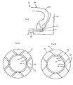
- FIG. 1 and Figures 2a and 2b there is shown a rigid core 1 according to the first embodiment.
- a plurality of circumferentially adjacent fractions 10d, 10i arranged side by side in contact with each other by their transverse faces 10d1 and 10i1.
- the transverse faces 10i1 of at least a fraction 10i are convergent outside the core, to allow disassembly of said core by removing this fraction radially from the inside.
- the nucleus comprises two fraction models: divergent fractions 10d, whose transverse faces 10d1 are divergent outside the core, and so-called "inverted" fractions 10i, whose transverse faces 10i1 are convergent outside the core.
- the fractions will be designated by omitting the suffix i or d, for example "fraction 10", when their diverging or inverted character is of no importance for the technical aspect treated.
- Each of said fractions 10 has an attachment portion 12 to a rim 14, said attachment portion 12 being arranged at the radially inner end of each of the fractions.
- Said hooking portion 12 is essentially made of a first material chosen for its ability to withstand a large number of assembly and disassembly cycles.
- Each of said fractions 10 has a main portion 13 integral with said attachment portion 12, the essential function of which is to define a manufacturing surface for the tire.
- This main part 13 is essentially made of a second material different from the first material chosen for its ability to be molded, its good thermal conductivity and its lightness, made integral with said attachment portion 12, that is to say not functionally removable.
- FIG. 2b we see a shell 15 which cooperates with the core 1 to define a mold cavity.
- a shell for each flank and also means (not shown) for molding the tread.
- the shell 15 molding the outer surface of a sidewall of a tire has, in its radially inner portion, an extension 140 which slides under the radially inner surface of the core. This makes it possible to isolate and completely close the molding space before each shell has reached its closed position. This is the most compact embodiment of the present invention.
- the attachment portions 12 have a contribution to the molding of the tire, since the line L1 separating the attachment portion 12 from the main part 13 is in the molding cavity of the tire.
- FIG. 3 there is shown a core 2 according to a second embodiment of the invention.
- a fraction 20 having an attachment portion 22 and a main portion 13 is recognized, the attachment portion 22 being mounted on a rim 24.
- the core 2 cooperates with a shell 25 (a shell for each sidewall) to define a cavity molding.
- a shell 25 a shell for each sidewall
- This intermediate face 21 is located radially under the molding portion of the fraction 20, and is either disposed in a plane perpendicular to the axis of rotation (as shown), or forms a very large, very open angle cone.
- junction line L2 between the attachment portion 22 and the main portion 23 is housed in this intermediate surface 21, so that it also avoids the appearance of any burr on the inner surface of the bead of the tire, due to the creep of rubber between gripping part and main part.
- such a core which comprises parts of different thermal expansion coefficients (steel for the fastening part and aluminum for the main part), accommodates thermal cycles caused by the manufacture of a tire.
- Such a core will be used at temperatures of the order of at least 150 ° C during vulcanization while during the manufacture of the green tire blank, it is used at temperatures below 100 ° C.
- the dimensioning of the main part 13 and its connection to its attachment portion 12 is such that, when using the core during the assembly of a raw tire, there remain games ( Figure 4a, at a temperature below the vulcanization temperature where, again, the play between the fractions 10 are exaggerated) between each of the fractions 10i and 10d which do not only when raising the temperature necessary for vulcanization (FIG. 4b, at the vulcanization temperature).
- a fraction 10, 20 always comprises a hooking portion 12, 22 arranged radially to the inner part thereof. It comprises a main part 13, 23 made of molded light alloy.
- FIGS. 5a and 5b show a main part 33 fastened to an attachment part 32 by means of screws 36 arranged laterally on either side of the fraction 30, and circumferentially substantially in the median part of the fraction.
- Such a connection between the hooking part 32 and the main part 33 since it is essentially central, will allow the main part to undergo larger expansions than the fastening part without any damage or at the attachment portion 32 nor at the main portion 33 nor at the screws 36 connecting the attachment portion and the main portion.
- hooking surfaces are strongly solicited at each assembly and each disassembly of the core. This part is very resistant by the choice of a suitable material. In addition, it is possible to provide all the appropriate surface treatments to ensure the good behavior over time of this area which undergoes a lot of shocks, hammering and friction during each cycle of assembly and disassembly of the core.
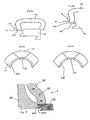
- FIG. 6a it can be seen that the zone 425 of the hooking part 42 extends radially in front of the bead B, so that the junction line L4 separating the hooking part 42 and the main part 43 appears on the inner surface. of bead B of the tire.
- the attachment portions form at least in the molding portion the tire a continuous surface (see Figure 6b). This is not necessarily the case when the molding surface is entirely located on the main portions 53 (see Figure 6d).
- junction line L5 separating fastening part 52 and main part 53 would appear in intermediate surface 51.
- the inner face of tire bead B is entirely molded by main part 53.
- the face P3, which in FIG. 6c is cylindrical, is slightly frustoconical.
- FIG 7 we see a detail of a main part of a fraction 70 very wide.
- the main part 73 is reinforced in its central part by posts 79 arranged substantially radially which connect the lower part of this main part to the radially outermost vault.
- a metal such as steel is typically used to make the fastening part.
- the steel is machined so as to obtain all the ranges and the desired shapes for this part of attachment according to the purposes of attachment and manipulation of the core.
- typically a cast light alloy such as an aluminum alloy is used for the main part. This allows overmoulding-that is to say, drowning-electrical resistances inside the wall forming the radially outer dome of each main part.
- FIG. 7 shows an electrical resistor 74, the radial section revealing twelve sections of this resistor 74 which is bent so as to form backward and forward movements of circumferentially oriented sections.
- a connector 75 is provided which makes it possible, when docking at a gripper on a vulcanization station, to connect the core with another connector.
- 76 at the vulcanization station of the machine for supplying the resistances with electrical energy and possibly to be able to connect probes of various measurements, or provision is made for the same purpose of inductive coupling means and / or any other usual coupling means.
- FIGS. 5b and 7 show an interesting variant embodiment comprising a circumferentially continuous rim 34, the core comprising at least one fraction-side hooking surface, arranged on the hooking part of each of the fractions, for example on a spout. 37 arranged circumferentially.
- the core also has a rim-side hooking surface, complementary to the fraction-side hooking surface, arranged on the rim and cooperating, for each fraction, with the fraction-side hooking surface to take up the efforts tending to radially separate the fractions with respect to the rim, in cooperation with locking means not shown, for example means for axially gripping the rim 34 against the attachment portion 32.
- each rim-side attachment surface is also performed on a beak 38 arranged circumferentially.
- said hooking surfaces on the fraction side and hooking surface on the rim side are shaped so as to allow relative axial movement of the rim with respect to all the fractions in one direction only.
- the nozzles 37 on the fractions are located at different levels, one, said lower nozzle, being arranged radially at a lower level than the other, said upper nozzle.
- each hooking surface is a frustoconical surface, said frustoconical surfaces being oriented axially on the same side of the core. More particularly, each frustoconical surface is of non-wedging angle.
- a fraction 80 having an attachment portion 82 and a main portion 83 is recognized.
- the core 8 cooperates with a shell 85 (a shell for each sidewall) to define a molding cavity.
- This variant shows a groove 840 provided on each hooking portion 82, to cooperate with a rib 850 arranged on the shell 85, so as to avoid any risk that the inverted fractions protrude relative to the divergent fractions.
Landscapes
- Engineering & Computer Science (AREA)
- Mechanical Engineering (AREA)
- Moulds For Moulding Plastics Or The Like (AREA)
- Heating, Cooling, Or Curing Plastics Or The Like In General (AREA)
- Lining Or Joining Of Plastics Or The Like (AREA)
- Tyre Moulding (AREA)
- Tires In General (AREA)
- Materials For Medical Uses (AREA)
Applications Claiming Priority (3)
| Application Number | Priority Date | Filing Date | Title |
|---|---|---|---|
| FR9910420 | 1999-08-10 | ||
| FR9910420 | 1999-08-10 | ||
| EP00116695A EP1075929B1 (fr) | 1999-08-10 | 2000-08-02 | Noyau rigide en deux parties, pour la fabrication de pneumatiques |
Related Parent Applications (1)
| Application Number | Title | Priority Date | Filing Date |
|---|---|---|---|
| EP00116695A Division EP1075929B1 (fr) | 1999-08-10 | 2000-08-02 | Noyau rigide en deux parties, pour la fabrication de pneumatiques |
Publications (3)
| Publication Number | Publication Date |
|---|---|
| EP1371479A2 EP1371479A2 (fr) | 2003-12-17 |
| EP1371479A3 EP1371479A3 (fr) | 2004-03-24 |
| EP1371479B1 true EP1371479B1 (fr) | 2006-02-01 |
Family
ID=9549093
Family Applications (3)
| Application Number | Title | Priority Date | Filing Date |
|---|---|---|---|
| EP03016412A Expired - Lifetime EP1371479B1 (fr) | 1999-08-10 | 2000-08-02 | Noyau rigide en deux parties, pour la fabrication de pneumatiques |
| EP03016411A Expired - Lifetime EP1371478B1 (fr) | 1999-08-10 | 2000-08-02 | Noyau rigide en deux parties, pour la fabrication de pneumatiques |
| EP00116695A Expired - Lifetime EP1075929B1 (fr) | 1999-08-10 | 2000-08-02 | Noyau rigide en deux parties, pour la fabrication de pneumatiques |
Family Applications After (2)
| Application Number | Title | Priority Date | Filing Date |
|---|---|---|---|
| EP03016411A Expired - Lifetime EP1371478B1 (fr) | 1999-08-10 | 2000-08-02 | Noyau rigide en deux parties, pour la fabrication de pneumatiques |
| EP00116695A Expired - Lifetime EP1075929B1 (fr) | 1999-08-10 | 2000-08-02 | Noyau rigide en deux parties, pour la fabrication de pneumatiques |
Country Status (5)
| Country | Link |
|---|---|
| US (1) | US6468062B1 (enExample) |
| EP (3) | EP1371479B1 (enExample) |
| JP (1) | JP4601784B2 (enExample) |
| AT (3) | ATE464174T1 (enExample) |
| DE (3) | DE60025855T2 (enExample) |
Families Citing this family (17)
| Publication number | Priority date | Publication date | Assignee | Title |
|---|---|---|---|---|
| JP4056290B2 (ja) | 2002-04-30 | 2008-03-05 | 株式会社ブリヂストン | 空気入りタイヤの製造方法および装置 |
| BR0211536B1 (pt) * | 2002-05-31 | 2011-06-28 | processo para fabricar um pneu e suporte toroidal para fabricar um pneu cru sobre o mesmo. | |
| EP1645404B1 (en) * | 2003-07-16 | 2013-08-21 | The Yokohama Rubber Co., Ltd. | Pneumatic tire producing method and tire forming drum |
| JP2007515310A (ja) | 2003-11-28 | 2007-06-14 | ピレリ・タイヤ・ソチエタ・ペル・アツィオーニ | タイヤを製造する方法及び前記方法を実行するためのトロイダル支持体 |
| US20070125497A1 (en) * | 2005-12-02 | 2007-06-07 | Lundell Dennis A | Heated tire building core assembly and method |
| FR2921859B1 (fr) * | 2007-10-08 | 2011-05-20 | Michelin Soc Tech | Noyau rigide pour la fabrication des pneumatiques. |
| US7910043B2 (en) * | 2007-12-21 | 2011-03-22 | The Goodyear Tire & Rubber Company | Tire building and cure station coupling apparatus and method |
| JP4297290B2 (ja) | 2007-12-21 | 2009-07-15 | 横浜ゴム株式会社 | 空気入りタイヤの製造方法 |
| JP4407773B1 (ja) | 2009-05-07 | 2010-02-03 | 横浜ゴム株式会社 | 空気入りタイヤの製造方法 |
| JP4816761B2 (ja) | 2009-05-07 | 2011-11-16 | 横浜ゴム株式会社 | 空気入りタイヤの製造方法 |
| JP5432955B2 (ja) * | 2011-06-24 | 2014-03-05 | 住友ゴム工業株式会社 | 剛性中子 |
| JP5261541B2 (ja) * | 2011-06-24 | 2013-08-14 | 住友ゴム工業株式会社 | 剛性中子 |
| JP5492149B2 (ja) * | 2011-06-27 | 2014-05-14 | 住友ゴム工業株式会社 | 剛性中子、及びそれを用いたタイヤの製造方法 |
| JP5698694B2 (ja) * | 2012-03-19 | 2015-04-08 | 住友ゴム工業株式会社 | タイヤ形成用の剛性中子 |
| JP6242146B2 (ja) * | 2013-10-10 | 2017-12-06 | 住友ゴム工業株式会社 | タイヤ形成用の剛性中子、及びそれを用いたタイヤ製造方法 |
| JP5913266B2 (ja) * | 2013-11-27 | 2016-04-27 | 住友ゴム工業株式会社 | タイヤの製造方法 |
| US10441503B2 (en) | 2016-12-27 | 2019-10-15 | Richard T. FRENCH | SPA with temperature responsive pump activation and deactivation independent of heater activation |
Family Cites Families (18)
| Publication number | Priority date | Publication date | Assignee | Title |
|---|---|---|---|---|
| US1303256A (en) * | 1919-05-13 | of cleveland | ||
| US1249033A (en) * | 1914-07-03 | 1917-12-04 | Us Rubber Co | Mandrel for vulcanizing tire-shoes. |
| US1221349A (en) * | 1916-12-30 | 1917-04-03 | Robert M Merriman | Collapsible core. |
| US1389892A (en) * | 1919-03-19 | 1921-09-06 | Fisk Rubber Co | Collapsible core |
| US1810072A (en) * | 1926-10-04 | 1931-06-16 | Gen Tire & Rubber Co | Pneumatic tire and method of and apparatus for building the same |
| US1903458A (en) * | 1930-01-11 | 1933-04-11 | Frank L Johnson | Collapsible core |
| US1954764A (en) * | 1931-11-14 | 1934-04-10 | Gen Tire & Rubber Co | Tire building core |
| AT338637B (de) * | 1975-03-24 | 1977-09-12 | Polyair Maschinenbau Gmbh | Giess- oder spritzform zur herstellung von reifen |
| US4083672A (en) * | 1977-03-28 | 1978-04-11 | The Firestone Tire & Rubber Company | Automatic hub and apparatus for disassembly of the hub |
| DE2900565A1 (de) * | 1979-01-09 | 1980-07-17 | Bayer Ag | Verfahren und vorrichtung zur reifenentformung bei segmentierten kernen |
| FR2460200A1 (fr) * | 1979-06-29 | 1981-01-23 | Michelin & Cie | Procede de fabrication de pneumatiques par moulage, et pneumatiques obtenus par ce procede |
| FR2597783B1 (fr) | 1986-04-25 | 1988-08-26 | Michelin & Cie | Moule rigide pour le moulage et la vulcanisation de pneumatiques |
| EP0320494B1 (fr) * | 1986-04-25 | 1991-10-09 | COMPAGNIE GENERALE DES ETABLISSEMENTS MICHELIN-MICHELIN & CIE | Moule rigide pour le moulage et la vulcanisation de pneumatiques |
| IT1189672B (it) * | 1986-05-20 | 1988-02-04 | Firestone Int Dev Spa | Metodo per la realizzazione a caldo di pneumatici |
| FR2712229A1 (fr) * | 1993-11-12 | 1995-05-19 | Sedepro | Moule pour pneumatique, et procédé de moulage du pneumatique. |
| US6113833A (en) * | 1997-07-22 | 2000-09-05 | Bridgestone Corporation | Segmented toroidal core for manufacturing pneumatic tires |
| JP3770705B2 (ja) * | 1997-07-22 | 2006-04-26 | 株式会社ブリヂストン | タイヤ製造用内型 |
| JP4191293B2 (ja) * | 1998-10-05 | 2008-12-03 | 株式会社ブリヂストン | タイヤ加硫成形金型及びタイヤ加硫成形方法 |
-
2000
- 2000-08-02 EP EP03016412A patent/EP1371479B1/fr not_active Expired - Lifetime
- 2000-08-02 EP EP03016411A patent/EP1371478B1/fr not_active Expired - Lifetime
- 2000-08-02 DE DE60025855T patent/DE60025855T2/de not_active Expired - Lifetime
- 2000-08-02 EP EP00116695A patent/EP1075929B1/fr not_active Expired - Lifetime
- 2000-08-02 AT AT03016411T patent/ATE464174T1/de not_active IP Right Cessation
- 2000-08-02 DE DE60010989T patent/DE60010989T2/de not_active Expired - Lifetime
- 2000-08-02 AT AT03016412T patent/ATE316861T1/de not_active IP Right Cessation
- 2000-08-02 DE DE60044212T patent/DE60044212D1/de not_active Expired - Lifetime
- 2000-08-02 AT AT00116695T patent/ATE267691T1/de not_active IP Right Cessation
- 2000-08-08 JP JP2000240295A patent/JP4601784B2/ja not_active Expired - Fee Related
- 2000-08-10 US US09/636,021 patent/US6468062B1/en not_active Expired - Lifetime
Also Published As
| Publication number | Publication date |
|---|---|
| ATE267691T1 (de) | 2004-06-15 |
| DE60010989D1 (de) | 2004-07-01 |
| DE60010989T2 (de) | 2005-05-19 |
| EP1371478A2 (fr) | 2003-12-17 |
| DE60025855D1 (de) | 2006-04-13 |
| JP2001088143A (ja) | 2001-04-03 |
| EP1075929B1 (fr) | 2004-05-26 |
| EP1371478A3 (fr) | 2004-03-24 |
| US6468062B1 (en) | 2002-10-22 |
| EP1371479A3 (fr) | 2004-03-24 |
| DE60044212D1 (de) | 2010-05-27 |
| EP1371479A2 (fr) | 2003-12-17 |
| ATE464174T1 (de) | 2010-04-15 |
| JP4601784B2 (ja) | 2010-12-22 |
| EP1371478B1 (fr) | 2010-04-14 |
| DE60025855T2 (de) | 2006-09-14 |
| EP1075929A1 (fr) | 2001-02-14 |
| ATE316861T1 (de) | 2006-02-15 |
Similar Documents
| Publication | Publication Date | Title |
|---|---|---|
| EP1371479B1 (fr) | Noyau rigide en deux parties, pour la fabrication de pneumatiques | |
| EP1637253B1 (fr) | Procédé de fabrication d'une aube de turbomachine, assemblage de noyaux pour la mise en oeuvre du procédé | |
| EP0799722B1 (fr) | Roue pour véhicules automobiles et procédé de fabrication d'une telle roue | |
| EP0242840A1 (fr) | Moule rigide pour le moulage et la vulcanisation des pneumatiques | |
| EP1636006A1 (fr) | Dispositif de moulage pour la fabrication de recipients en materiau thermoplastique | |
| FR2800295A1 (fr) | Roue pour patin | |
| FR3112999A1 (fr) | Siège de véhicule | |
| EP3766715B1 (fr) | Insert de renfort muni d'orifices traversants | |
| CA2667006A1 (fr) | Outil composite pour le moulage de pieces cylindriques | |
| FR2951401A1 (fr) | Presse de vulcanisation | |
| EP1381499B1 (fr) | Procede et moule pour deposer un motif de couleur sur un pneumatique | |
| EP0799721B1 (fr) | Roue pour véhicules automobiles | |
| FR2701899A1 (fr) | Jante et roue pour cycle et leur procédé de fabrication. | |
| WO2021089390A1 (fr) | Volant de direction | |
| FR2459056A1 (fr) | Poids pour halteres et outillage pour sa fabrication | |
| EP2611706B1 (fr) | Moule pour la fabrication par injection d'une gaine pour un contenant tel qu'une bouteille ou un flacon, et procédé de moulage utilisant un tel moule | |
| EP1000728B1 (fr) | Fabrication d'un appui | |
| FR2948894A1 (fr) | Procede de surmoulage, et moule pour sa mise en oeuvre | |
| EP0881059B1 (fr) | Fabrication d'un pneu dans lequel la bande de roulement est réalisée à partir de plusieurs parties prévulcanisées | |
| EP2218566B1 (fr) | Procédé de fabrication par moulage sous pression d'une pièce composite à structure monolithique creuse | |
| FR2479072A1 (fr) | Element moule comprenant une levre saillante rabattable sans formation de surepaisseur, roulette de meuble realisee a partir de cet element et procede et moule pour sa fabrication | |
| FR2863145A1 (fr) | Accessoire de parisserie associe a un module recevant une epaisseur de pate a cuire avec un bord peripherique releve | |
| FR2848619A1 (fr) | Helice de refroidissement moteur | |
| FR3113472A1 (fr) | Moule de cuisson pour pneumatique comportant des moyens de découpage d’une bavure de gomme | |
| FR2978069A1 (fr) | Moule pour piece de turbomachine d'aeronef comprenant un dispositif ameliore de support d'inserts destines a etre integres a la piece |
Legal Events
| Date | Code | Title | Description |
|---|---|---|---|
| PUAI | Public reference made under article 153(3) epc to a published international application that has entered the european phase |
Free format text: ORIGINAL CODE: 0009012 |
|
| AC | Divisional application: reference to earlier application |
Ref document number: 1075929 Country of ref document: EP Kind code of ref document: P |
|
| AK | Designated contracting states |
Kind code of ref document: A2 Designated state(s): AT BE CH CY DE DK ES FI FR GB GR IE IT LI LU MC NL PT SE |
|
| RIN1 | Information on inventor provided before grant (corrected) |
Inventor name: LADOUCE, JEAN-PIERRE Inventor name: SOULALIOUX, ALAIN |
|
| PUAL | Search report despatched |
Free format text: ORIGINAL CODE: 0009013 |
|
| AK | Designated contracting states |
Kind code of ref document: A3 Designated state(s): AT BE CH CY DE DK ES FI FR GB GR IE IT LI LU MC NL PT SE |
|
| RIC1 | Information provided on ipc code assigned before grant |
Ipc: 7B 29C 33/48 B Ipc: 7B 29D 30/12 A |
|
| RAP1 | Party data changed (applicant data changed or rights of an application transferred) |
Owner name: SEDEPRO |
|
| 17P | Request for examination filed |
Effective date: 20040924 |
|
| AKX | Designation fees paid |
Designated state(s): AT BE CH CY DE DK ES FI FR GB GR IE IT LI LU MC NL PT SE |
|
| GRAP | Despatch of communication of intention to grant a patent |
Free format text: ORIGINAL CODE: EPIDOSNIGR1 |
|
| GRAS | Grant fee paid |
Free format text: ORIGINAL CODE: EPIDOSNIGR3 |
|
| GRAA | (expected) grant |
Free format text: ORIGINAL CODE: 0009210 |
|
| AC | Divisional application: reference to earlier application |
Ref document number: 1075929 Country of ref document: EP Kind code of ref document: P |
|
| AK | Designated contracting states |
Kind code of ref document: B1 Designated state(s): AT BE CH CY DE DK ES FI FR GB GR IE IT LI LU MC NL PT SE |
|
| PG25 | Lapsed in a contracting state [announced via postgrant information from national office to epo] |
Ref country code: IE Free format text: LAPSE BECAUSE OF FAILURE TO SUBMIT A TRANSLATION OF THE DESCRIPTION OR TO PAY THE FEE WITHIN THE PRESCRIBED TIME-LIMIT Effective date: 20060201 Ref country code: FI Free format text: LAPSE BECAUSE OF FAILURE TO SUBMIT A TRANSLATION OF THE DESCRIPTION OR TO PAY THE FEE WITHIN THE PRESCRIBED TIME-LIMIT Effective date: 20060201 Ref country code: AT Free format text: LAPSE BECAUSE OF FAILURE TO SUBMIT A TRANSLATION OF THE DESCRIPTION OR TO PAY THE FEE WITHIN THE PRESCRIBED TIME-LIMIT Effective date: 20060201 |
|
| REG | Reference to a national code |
Ref country code: GB Ref legal event code: FG4D Free format text: NOT ENGLISH |
|
| REG | Reference to a national code |
Ref country code: CH Ref legal event code: EP |
|
| REG | Reference to a national code |
Ref country code: IE Ref legal event code: FG4D Free format text: LANGUAGE OF EP DOCUMENT: FRENCH |
|
| RAP2 | Party data changed (patent owner data changed or rights of a patent transferred) |
Owner name: MANUFACTURE FRANCAISE DES PNEUMATIQUES MICHELIN |
|
| REF | Corresponds to: |
Ref document number: 60025855 Country of ref document: DE Date of ref document: 20060413 Kind code of ref document: P |
|
| PG25 | Lapsed in a contracting state [announced via postgrant information from national office to epo] |
Ref country code: SE Free format text: LAPSE BECAUSE OF FAILURE TO SUBMIT A TRANSLATION OF THE DESCRIPTION OR TO PAY THE FEE WITHIN THE PRESCRIBED TIME-LIMIT Effective date: 20060501 Ref country code: DK Free format text: LAPSE BECAUSE OF FAILURE TO SUBMIT A TRANSLATION OF THE DESCRIPTION OR TO PAY THE FEE WITHIN THE PRESCRIBED TIME-LIMIT Effective date: 20060501 |
|
| PG25 | Lapsed in a contracting state [announced via postgrant information from national office to epo] |
Ref country code: ES Free format text: LAPSE BECAUSE OF FAILURE TO SUBMIT A TRANSLATION OF THE DESCRIPTION OR TO PAY THE FEE WITHIN THE PRESCRIBED TIME-LIMIT Effective date: 20060512 |
|
| GBT | Gb: translation of ep patent filed (gb section 77(6)(a)/1977) |
Effective date: 20060424 |
|
| NLT2 | Nl: modifications (of names), taken from the european patent patent bulletin |
Owner name: MANUFACTURE FRANEAISE DES PNEUMATIQUES MICHELIN Effective date: 20060412 |
|
| PG25 | Lapsed in a contracting state [announced via postgrant information from national office to epo] |
Ref country code: PT Free format text: LAPSE BECAUSE OF FAILURE TO SUBMIT A TRANSLATION OF THE DESCRIPTION OR TO PAY THE FEE WITHIN THE PRESCRIBED TIME-LIMIT Effective date: 20060703 |
|
| PG25 | Lapsed in a contracting state [announced via postgrant information from national office to epo] |
Ref country code: CH Free format text: LAPSE BECAUSE OF NON-PAYMENT OF DUE FEES Effective date: 20060831 Ref country code: MC Free format text: LAPSE BECAUSE OF NON-PAYMENT OF DUE FEES Effective date: 20060831 Ref country code: BE Free format text: LAPSE BECAUSE OF NON-PAYMENT OF DUE FEES Effective date: 20060831 Ref country code: LI Free format text: LAPSE BECAUSE OF NON-PAYMENT OF DUE FEES Effective date: 20060831 |
|
| REG | Reference to a national code |
Ref country code: IE Ref legal event code: FD4D |
|
| PLBE | No opposition filed within time limit |
Free format text: ORIGINAL CODE: 0009261 |
|
| STAA | Information on the status of an ep patent application or granted ep patent |
Free format text: STATUS: NO OPPOSITION FILED WITHIN TIME LIMIT |
|
| 26N | No opposition filed |
Effective date: 20061103 |
|
| REG | Reference to a national code |
Ref country code: CH Ref legal event code: PL |
|
| PGFP | Annual fee paid to national office [announced via postgrant information from national office to epo] |
Ref country code: LU Payment date: 20070820 Year of fee payment: 8 |
|
| BERE | Be: lapsed |
Owner name: SEDEPRO Effective date: 20060831 |
|
| PGFP | Annual fee paid to national office [announced via postgrant information from national office to epo] |
Ref country code: GB Payment date: 20070823 Year of fee payment: 8 |
|
| PGFP | Annual fee paid to national office [announced via postgrant information from national office to epo] |
Ref country code: NL Payment date: 20070814 Year of fee payment: 8 |
|
| PG25 | Lapsed in a contracting state [announced via postgrant information from national office to epo] |
Ref country code: GR Free format text: LAPSE BECAUSE OF FAILURE TO SUBMIT A TRANSLATION OF THE DESCRIPTION OR TO PAY THE FEE WITHIN THE PRESCRIBED TIME-LIMIT Effective date: 20060502 |
|
| PG25 | Lapsed in a contracting state [announced via postgrant information from national office to epo] |
Ref country code: CY Free format text: LAPSE BECAUSE OF FAILURE TO SUBMIT A TRANSLATION OF THE DESCRIPTION OR TO PAY THE FEE WITHIN THE PRESCRIBED TIME-LIMIT Effective date: 20060201 |
|
| GBPC | Gb: european patent ceased through non-payment of renewal fee |
Effective date: 20080802 |
|
| NLV4 | Nl: lapsed or anulled due to non-payment of the annual fee |
Effective date: 20090301 |
|
| PG25 | Lapsed in a contracting state [announced via postgrant information from national office to epo] |
Ref country code: NL Free format text: LAPSE BECAUSE OF NON-PAYMENT OF DUE FEES Effective date: 20090301 |
|
| PG25 | Lapsed in a contracting state [announced via postgrant information from national office to epo] |
Ref country code: GB Free format text: LAPSE BECAUSE OF NON-PAYMENT OF DUE FEES Effective date: 20080802 |
|
| PG25 | Lapsed in a contracting state [announced via postgrant information from national office to epo] |
Ref country code: LU Free format text: LAPSE BECAUSE OF NON-PAYMENT OF DUE FEES Effective date: 20080802 |
|
| REG | Reference to a national code |
Ref country code: FR Ref legal event code: PLFP Year of fee payment: 16 |
|
| PGFP | Annual fee paid to national office [announced via postgrant information from national office to epo] |
Ref country code: DE Payment date: 20150821 Year of fee payment: 16 |
|
| PGFP | Annual fee paid to national office [announced via postgrant information from national office to epo] |
Ref country code: FR Payment date: 20150820 Year of fee payment: 16 |
|
| PGFP | Annual fee paid to national office [announced via postgrant information from national office to epo] |
Ref country code: IT Payment date: 20150824 Year of fee payment: 16 |
|
| REG | Reference to a national code |
Ref country code: DE Ref legal event code: R119 Ref document number: 60025855 Country of ref document: DE |
|
| REG | Reference to a national code |
Ref country code: FR Ref legal event code: ST Effective date: 20170428 |
|
| PG25 | Lapsed in a contracting state [announced via postgrant information from national office to epo] |
Ref country code: FR Free format text: LAPSE BECAUSE OF NON-PAYMENT OF DUE FEES Effective date: 20160831 Ref country code: DE Free format text: LAPSE BECAUSE OF NON-PAYMENT OF DUE FEES Effective date: 20170301 |
|
| PG25 | Lapsed in a contracting state [announced via postgrant information from national office to epo] |
Ref country code: IT Free format text: LAPSE BECAUSE OF NON-PAYMENT OF DUE FEES Effective date: 20160802 |