EP1368962B1 - Correction techniques for soft proofing - Google Patents
Correction techniques for soft proofing Download PDFInfo
- Publication number
- EP1368962B1 EP1368962B1 EP02717666A EP02717666A EP1368962B1 EP 1368962 B1 EP1368962 B1 EP 1368962B1 EP 02717666 A EP02717666 A EP 02717666A EP 02717666 A EP02717666 A EP 02717666A EP 1368962 B1 EP1368962 B1 EP 1368962B1
- Authority
- EP
- European Patent Office
- Prior art keywords
- color
- values
- display device
- matrix
- white
- Prior art date
- Legal status (The legal status is an assumption and is not a legal conclusion. Google has not performed a legal analysis and makes no representation as to the accuracy of the status listed.)
- Expired - Lifetime
Links
- 238000012937 correction Methods 0.000 title claims abstract description 82
- 238000000034 method Methods 0.000 title claims abstract description 56
- 239000011159 matrix material Substances 0.000 claims description 85
- 230000000007 visual effect Effects 0.000 claims description 41
- 239000003086 colorant Substances 0.000 claims description 31
- 230000008569 process Effects 0.000 claims description 10
- OAICVXFJPJFONN-UHFFFAOYSA-N Phosphorus Chemical compound [P] OAICVXFJPJFONN-UHFFFAOYSA-N 0.000 claims description 8
- 238000012512 characterization method Methods 0.000 claims description 3
- 238000012986 modification Methods 0.000 claims description 3
- 230000004048 modification Effects 0.000 claims description 3
- 230000009466 transformation Effects 0.000 description 30
- 230000001419 dependent effect Effects 0.000 description 23
- 238000003384 imaging method Methods 0.000 description 14
- 230000006870 function Effects 0.000 description 8
- XOFYZVNMUHMLCC-ZPOLXVRWSA-N prednisone Chemical compound O=C1C=C[C@]2(C)[C@H]3C(=O)C[C@](C)([C@@](CC4)(O)C(=O)CO)[C@@H]4[C@@H]3CCC2=C1 XOFYZVNMUHMLCC-ZPOLXVRWSA-N 0.000 description 8
- 229920006395 saturated elastomer Polymers 0.000 description 8
- 101150097247 CRT1 gene Proteins 0.000 description 7
- 238000010586 diagram Methods 0.000 description 6
- 238000007726 management method Methods 0.000 description 6
- 238000005259 measurement Methods 0.000 description 5
- 238000006243 chemical reaction Methods 0.000 description 4
- 238000009877 rendering Methods 0.000 description 4
- 238000002474 experimental method Methods 0.000 description 3
- 230000015556 catabolic process Effects 0.000 description 2
- 238000005516 engineering process Methods 0.000 description 2
- 239000007787 solid Substances 0.000 description 2
- 238000000844 transformation Methods 0.000 description 2
- 230000006978 adaptation Effects 0.000 description 1
- 238000013459 approach Methods 0.000 description 1
- 230000008901 benefit Effects 0.000 description 1
- 238000004364 calculation method Methods 0.000 description 1
- 238000004590 computer program Methods 0.000 description 1
- 230000007812 deficiency Effects 0.000 description 1
- 235000013399 edible fruits Nutrition 0.000 description 1
- 230000000694 effects Effects 0.000 description 1
- 238000013401 experimental design Methods 0.000 description 1
- 230000008570 general process Effects 0.000 description 1
- 239000004973 liquid crystal related substance Substances 0.000 description 1
- PWPJGUXAGUPAHP-UHFFFAOYSA-N lufenuron Chemical compound C1=C(Cl)C(OC(F)(F)C(C(F)(F)F)F)=CC(Cl)=C1NC(=O)NC(=O)C1=C(F)C=CC=C1F PWPJGUXAGUPAHP-UHFFFAOYSA-N 0.000 description 1
- 230000007935 neutral effect Effects 0.000 description 1
- 230000003287 optical effect Effects 0.000 description 1
- 238000011160 research Methods 0.000 description 1
- 230000009897 systematic effect Effects 0.000 description 1
- 238000012360 testing method Methods 0.000 description 1
- 230000001131 transforming effect Effects 0.000 description 1
Images


Classifications
-
- H—ELECTRICITY
- H04—ELECTRIC COMMUNICATION TECHNIQUE
- H04N—PICTORIAL COMMUNICATION, e.g. TELEVISION
- H04N1/00—Scanning, transmission or reproduction of documents or the like, e.g. facsimile transmission; Details thereof
- H04N1/46—Colour picture communication systems
- H04N1/56—Processing of colour picture signals
- H04N1/60—Colour correction or control
- H04N1/6011—Colour correction or control with simulation on a subsidiary picture reproducer
-
- H—ELECTRICITY
- H04—ELECTRIC COMMUNICATION TECHNIQUE
- H04N—PICTORIAL COMMUNICATION, e.g. TELEVISION
- H04N1/00—Scanning, transmission or reproduction of documents or the like, e.g. facsimile transmission; Details thereof
- H04N1/46—Colour picture communication systems
- H04N1/56—Processing of colour picture signals
- H04N1/60—Colour correction or control
- H04N1/603—Colour correction or control controlled by characteristics of the picture signal generator or the picture reproducer
- H04N1/6052—Matching two or more picture signal generators or two or more picture reproducers
-
- H—ELECTRICITY
- H04—ELECTRIC COMMUNICATION TECHNIQUE
- H04N—PICTORIAL COMMUNICATION, e.g. TELEVISION
- H04N1/00—Scanning, transmission or reproduction of documents or the like, e.g. facsimile transmission; Details thereof
- H04N1/46—Colour picture communication systems
- H04N1/56—Processing of colour picture signals
- H04N1/60—Colour correction or control
- H04N1/6083—Colour correction or control controlled by factors external to the apparatus
- H04N1/6088—Colour correction or control controlled by factors external to the apparatus by viewing conditions, i.e. conditions at picture output
Definitions
- the invention relates to color imaging and, more particularly, to techniques for presentation of color images on display devices.
- Color imaging devices use combinations of different device-dependent coordinates to form color images for display or printout on media such as paper or film.
- Many hardcopy printing devices use combinations of cyan, magenta, yellow, and black (CMYK) to form color imagery. These device-dependent coordinates of C, M, Y and K may be combined to form a gamut of colorimetric values that the device is capable of producing.
- Display devices such as cathode ray tubes (CRTs) or flat panel monitors, may use the device-dependent coordinates of red, green, and blue (RGB).
- Some high-fidelity color imaging devices may use the device-dependent coordinates cyan, magenta, yellow, and black in combination with other coordinates such as orange and green. These and other device-dependent coordinate systems have been developed for use with various color imaging devices.
- a point in a device-independent color space theoretically defines a color value irrespective of any particular device coordinates.
- a point in L*a*b* space or XYZ space can be mapped to a point in a device gamut. That point in the device gamut, in turn, defines the device-dependent coordinates that will theoretically cause the device to produce a color that is visually equivalent to that defined by the point in L*a*b* space or XYZ space.
- soft proofing refers to a proofing process that makes use of a display device rather than a printed hard copy.
- color proofing techniques have relied on “hard copy proofing,” where proofs are printed out on paper or other print media and inspected to ensure that the images and colors look visually correct. For instance, color characteristics can be adjusted and successive hard copy prints can be examined in the hard copy proofing process. After determining that a particular proof is acceptable, the color characteristics used to make the acceptable proof can be reused to mass-produce, e.g., on a printing press, large quantities of print media that look visually equivalent to the acceptable proof.
- Soft proofing is highly desirable for many reasons. For instance, soft proofing can remove the need to print copies of the media during the proofing process. Moreover, soft proofing may allow multiple proofing specialists to proof color images from remote locations simply by looking at display devices, rather than awaiting delivery of hard copies. Soft proofing can be faster and more convenient than hard proofing. Moreover, soft proofing can reduce the cost of the proofing process. For these and other reasons, soft proofing is highly desirable.
- a major problem with soft proofing is the difficulty in achieving a good visual match between the colors displayed on the soft proofing display device and the colors that appear on the actual printed hard copy.
- device-independent coordinates theoretically standardize color specification.
- the CMYK device coordinates of a hard copy printout could be converted to device-independent coordinates and then converted to RGB device coordinates.
- the colors displayed using the RGB device coordinates would be visually equivalent to those of the hard copy print out.
- the colors that appear on the display may look different than those of the hard copy printout, even though the images displayed by the soft and hard copy media produce substantially identical device-independent values.
- Soft proofing cannot work effectively, and gain widespread adoption in the industry, if the colors on the soft proofing display device do not provide an acceptable visual match with the colors on hard copy printouts.
- BRAUN K M ET AL "Psychophysical generation of matching images for cross-media color reproduction" FINAL PROGRAM AND PROCEEDINGS OF IS&T/SID FOURTH COLOR IMAGING CONFERENCE: COLOR SCIENCE, SYSTEMS AND APPLICATIONS, PROCEEDINGS OF THE FOURTH COLOR IMAGING CONFERENCE: COLOR SCIENCE, SYSTEMS AND APPLICATIONS; SCOTTSDALE, AZ, USA, 19-22 NOV. 1996, pages 214-220, XP002205203 1996, Springfield, VA, USA, Soc. Imaging Sci.
- US-A-5,739,809 discloses a system for allowing unique, customized adjustments to a display that can be saved as multiple options for how color is viewed.
- the display can have multiple calibration states that are defined by the user and selected as the user wishes.
- US-A-5,739,809 is a convenient means for obtaining a preferred look of color on screen, which may vary depending on the subject matter and preferences of the user.
- the invention provides a method according to claim 1. Individual embodiments of the invention are the subject matter of claims 2 to 9.
- a method includes obtaining a white point correction for a display device and obtaining a chromatic correction for the display device.
- the method may also include generating corrected color coordinates based on the white point and chromatic corrections.
- the method may further comprise obtaining the white point correction by determining a white point correction matrix and obtaining the chromatic correction by determining a chromatic correction matrix.
- Determining a white point correction matrix may comprise displaying a color on a display device, the color being defined by an original white point matrix in a known illuminant condition, e.g., D50, and adjusting at least some white point matrix values so that visual appearance on the display device is visually equivalent to a print. Adjusting at least some white point matrix values may comprise adjusting maximum phosphor settings on a display.
- Determining a chromatic correction matrix may comprise displaying a color on a display device, the color being defined by an original chromatic matrix in a known illuminant condition, e.g., D50, and adjusting at least some chromatic matrix values so that visual appearance on the display device is visually equivalent to a print. Adjusting at least some chromatic matrix values may comprise adjusting chromaticity values in an RGB color space such as the AdobeRGB(d50) color space.
- a method in another embodiment, includes determining device-independent coordinates defining a color on a hard copy, and generating corrected coordinates using the device-independent coordinates, a white point correction and a chromatic correction. Moreover, the method may further comprise displaying the color using the corrected coordinates. The displayed color may be visually equivalent to the color on the hard copy.
- the white point correction may be a white point correction matrix and the chromatic correction may be chromatic correction matrix.
- These matrices may be determined based on characterization of the output of a display device. For instance, determining the white point correction matrix may comprise displaying a color on a display device, the color being defined by an original white point matrix in a known illuminant condition, e.g., D50, and adjusting at least some white point matrix values so that visual appearance on the display device is visually equivalent to a white printout viewed in the known illuminant condition.
- a known illuminant condition e.g., D50
- determining the chromatic correction matrix may comprise displaying a color on a display device, the color being defined by an original chromatic matrix in a known illuminant condition, e.g., D50, and adjusting at least some chromatic matrix values so that visual appearance on the display device is visually equivalent to a color printout viewed in the known illuminant condition.
- a known illuminant condition e.g., D50
- a method in another embodiment, includes converting device-dependent coordinates that define a color in a printing device to device-independent coordinates, and adjusting the device-independent coordinates using a white point correction and a chromatic correction.
- the method may further comprise converting the corrected device-independent coordinates to device-dependent coordinates that define a color in a display device.
- the method may further comprise displaying the color using the corrected coordinates.
- the displayed color for instance, may be visually equivalent to the color on the hard copy.
- the white point correction may be a white point correction matrix and the chromatic correction may be chromatic correction matrix.
- a method in another embodiment, includes adjusting maximum phosphor values for a display device so that a first color displayed on the display device matches white in a defined illuminant condition for a hard copy, and adjusting color settings so that a second color displayed on the display device matches a defined color in the defined illuminant condition.
- the defined illuminant condition may be a D50 illuminant condition.
- Adjusting color settings may comprise adjusting color settings within a computer program.
- adjusting color settings may comprise adjusting chromaticity values in an RGB color space such as an AdobeRGB(50) color space.
- a method in still another embodiment, includes creating a first visual representation of an image on a hard copy, and creating a second visual representation of the image on a display device.
- the first visual representation and the second visual representation may have different device-independent coordinates.
- both white point and saturated colors on the display device may be a good visual match to those of the hard copy. Indeed, both white point and saturated colors on the display may even be visually equivalent to those of the hard copy.
- the invention comprises a system including a display device and memory device coupled to a processor.
- the processor may perform one or more of the methods described above.
- the invention comprises a computer readable medium that carries program code that when executed performs one or more of the methods described above.
- the invention comprises a computer readable medium carrying a color profile data structure thereon.
- the color profile data structure may correspond to a first device and may include illuminant condition values that do not correspond to actual illuminant conditions associated with the first device.
- An image rendered on a second device using the color profile data structure may be visually equivalent to the image rendered on the first device.
- the invention comprises methods, systems and computer readable media carrying program code that facilitate soft proofing.
- the invention may implement one or more transformation techniques to transform color coordinates between hard copy and soft copy proofing environments. The transformation ensures that color images that appear on a display device will be a visually acceptable match to color images that appear on print media.
- the invention is a method that includes adjusting the maximum phosphor values for a display device so that a first color displayed on the display device matches white in a defined illuminant condition for a hard copy.
- the method may also include adjusting color settings so that a second color displayed on the display device matches a defined color in the defined illuminant condition.
- the method may ensure that images that appear on a display device in a soft proofing environment will be visually equivalent to images that appear on print media.
- soft proofing technology seeks to display color images on a display device that are a "visually acceptable match,” “visually equivalent,” or a "good visual match” to color images on print media.
- Two images are “visually equivalent” if their empirical delta E error is approximately equal to, or less than 1.
- a good visual match occurs when a person trained in color management cannot visually identify a difference between the color values of two color images.
- a visually acceptable match is a match that is acceptable in a soft proofing environment.
- the value of empirical delta E can be determined for a single color by displaying an RGB color on a CRT.
- a hard copy of the color can be placed adjacent to the CRT for comparison.
- Several operators trained in color management can compare the color on the hard copy to that on the CRT, and can adjust the RGB value of the color on the CRT so the color on the CRT matches that of the hard copy. If necessary, effects of scattered light can be eliminated by viewing and comparing the two colors through a telescopic-like tube.
- the CRT and hard copy colors may be said to have an empirical delta E that is near zero. If the average deltas are non-zero, the empirical delta E can be determined by converting RGB to L*a*b* using the display ICC profile for the original RGB and the average adjusted RGB. The delta E can then be computed from the L*a*b* values.
- Imaging devices include printing devices and display devices.
- Printing devices may include, for example, laser printers, ink jet printers, thermal imagers, dot matrix printers, printing presses or any other device capable of printing to tangible media such as paper or film.
- Display devices include cathode ray tubes (CRTs), liquid crystal displays (LCDs) and other flat screen displays, digital paper, electronic ink displays, and any other device capable of rendering images from electronic input signals or data.
- printing devices and display devices both make use of device-dependent coordinates to define color.
- Printing devices typically use CMYK or CMYKOG coordinates to define color, and therefore, printing devices may have an associated CMYK gamut or CMYKOG gamut defining the color capabilities of the printing device.
- Many display devices currently use RGB coordinates to define color, and therefore, typically have an associated RGB gamut that defines the color capabilities of the display device.
- a CRT display device for instance, makes use of different combinations of red, green and blue phosphors that can display colors within the RGB gamut of the device.
- the visual appearance of a color is also dependent on illuminant conditions. For instance, the same printout may look different when viewed under different lighting. For this reason, the illuminant condition is generally a fixed variable when comparing colors defined by one or more color spaces. The illuminant condition is important in both hard copy and soft proofing environments.
- a display device and printing device can produce color images that have the same measured XYZ coordinates, yet the images can look visually different.
- CRT displays that are calibrated to a D50 illuminant condition look yellow when compared to printed images with the same XYZ coordinates viewed in a D50 illuminant condition.
- Figure 1 is a flow diagram illustrating a color transformation process according to an embodiment of the invention.
- a first set of device-dependent coordinates are converted to device-independent coordinates (11).
- the device-independent coordinates are then transformed (12).
- the transformed device-independent coordinates are then converted to a second set of device-dependent coordinates (13).
- the process of Figure 1 for instance, can be performed on all of the pixels in a color image so that the output of a second imaging device, e.g., a display, looks visually equivalent to the output of a first imaging device, e.g., a printer.
- Figure 2 is a flow diagram illustrating one implementation of the process of Figure 1.
- the image data of a hard copy CMYK image is converted from CMYK coordinates to XYZ coordinates (21).
- the XYZ coordinates are then transformed to X'Y'Z' (22).
- These transformed X'Y'Z' coordinates can then be converted to RGB coordinates (23) for presentation on a display device for soft proofing.
- the output of a display device using the RGB coordinates can be made to be visually equivalent to a hard copy printed with the CMYK coordinates.
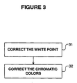
- Figure 3 is a flow diagram of a general process that can be implemented to transform device-independent coordinates. As shown, a white point is corrected (31) and then chromatic colors are corrected (32). Bifurcating the transformation process in this manner can yield accurate color matching results.
- the first set of device-independent coordinates may be associated with a first device.
- the first device may be printer that prints color images according to a CMYK gamut.
- the color image may be comprised of a collection of device-dependent coordinates that define the colors of the points in the image.
- an image may be comprised of image data that includes a large collection of CMYK coordinates.
- Each of these coordinates can be converted to device-independent coordinates (11), and then transformed (12).
- Each transformed coordinate may then be converted to form a second set of device-dependent coordinates (13).
- the second set of device-dependent coordinates may be associated with a second imaging device.
- the second imaging device is a display device such as a CRT
- the second set of device-dependent coordinates may be a collection of RGB coordinates. Each RGB coordinate can be generated from the transformed coordinates.
- Transformation (12) is important in obtaining accurate color matching. Transformation (12) adjusts device-independent coordinates to ensure that the output on a display device, for example, looks substantially the same as the print out of a printer. While this transformation may be "theoretically" unnecessary, given the widely-accepted CIE color equations, the general breakdown in color science discussed above mandates the use of this transformation, especially in the field of soft proofing where color matching is critical. Thus, the invention compensates for color matching deficiencies that arise in the conventional XYZ transformations in the context of hard copy to soft copy matching.
- the white point of a display device can be corrected (31) by starting with a known illuminant condition such as D50.
- a white surface can be placed in a viewing booth having D50 lighting to define a white point.
- Reflectance of the white surface can be measured in terms of device-independent coordinates such as L*a*b*.
- a white area with the same L*a*b* values can be created and displayed on a display device using commercially available software such as Adobe® PhotoShop®, available from Adobe Systems, Inc. of San Jose, California.
- the x and y chromaticities of the white point on the display device can be adjusted until the white image on the display device and the white image in the viewing booth are either visually equivalent, a good visual match, or a visually acceptable match.
- the adjustments to the x and y chromaticities of the white point should be noted. Having made the adjustments, the display device may be categorized as being calibrated to a "visual D50" white point In this case, the white points presented by the display and hard copy produce slightly different XYZ values, but appear to be a visual match.
- the chromatic colors may be corrected (32).
- the correction to the chromatic colors may be categorized as a correction to the saturated colors in the device gamut. For instance, if the correction is being applied to a CRT defined by an RGB gamut, the correction to the chromatic colors may be an adjustment to the R, G, and B chromaticities.
- the correction to the chromatic colors involves first determining correction values.
- a CMYK image should be converted to digital form.
- a CMYK image can be converted to AdobeRGB(50) using absolute rendering intent with an accurate Matchprint TM profile as measured by a spectrophotometer, i.e., a profile for the output of an Imation Matchprint TM laser proofer commercially available from Imation Corp. of Oakdale, Minnesota.
- the image used for comparison should contain 100% solids and overprints of C, M, Y, R (e.g., M+Y), G (e.g., C+Y), and B (e.g., C+M), although the invention is not limited in that respect.
- the RGB working space should be set to AdobeRGB(D50).
- the digital image can be compared to the CMYK Matchprint TM hard copy in a viewing station and the R, G, and B chromaticities of the AdobeRGB(D50) working space can be adjusted until either a visually acceptable match or a good visual match is achieved, or until the two images are visually equivalent. Again, the adjustments to the R, G, and B chromaticities of the display device working space should be noted.
- Figure 4 is another flow diagram according to an embodiment of the invention.
- Figure 4 illustrates one method that can be implemented to correct a white point in a soft proofing setting.
- an RGB working space is first set to the hard copy illuminant condition (41).
- the illuminant condition may be a D50 illuminant condition.
- an RGB soft copy of white can be displayed next to a CMYK hard copy of white (42).
- a white area with the same L*a*b* values as that of a white CMYK hard copy can be created in the RGB working space and displayed next to the CMYK hard copy.
- the illuminant condition illuminating the CMYK hard copy should still be D50.
- the soft copy of white can then be visually compared to the hard copy white (43).
- the maximum phosphor settings on the display device can be adjusted to achieve a visual match between the hard copy and soft copy (44).
- the phosphor settings can be incrementally adjusted by a user, for instance, until the white that appears on the display looks the same as the white on the hard copy. Once a visual match of white is achieved, the amount of adjustment to the phosphor settings can be documented (45).
- FIG. 5 is another flow diagram according to an embodiment of the invention: As shown, a CMYK image is converted to RGB coordinates (51). For example, a CMYK image can be converted to AdobeRGB(D50) using absolute rendering intent with an accurate Matchprint TM profile as measured by a spectrophotometer, i.e., a profile for the output of an Imation Matchprint TM laser proofer commercially available from Imation Corp. of Oakdale, Minnesota. Optimally, the image should contain 100% solids and overprints of C, M, Y, R, G, and B, although the invention is not limited in that respect.
- the working space can be set according to the hard copy illuminant condition (52). For example if the hard copy illuminant condition is D50, the RGB working space should be set to AdobeRGB(D50).
- the phosphor settings of the display can be adjusted to correspond to a visual white point (53).
- Figure 4 illustrates an appropriate method for determining a visual white point of a display.
- an RGB soft copy of the image can be displayed next to a CMYK hard copy of the image (54). Again, the CMYK hard copy should still be illuminated with a D50 illuminant. The hard copy of the image can then be visually compared to the soft copy of the image (55).
- a viewing station for example, may be implemented to ensure that D50 illuminant conditions are achieved when the soft copy is compared to the hard copy.
- the R, G, and B chromaticities of the AdobeRGB(D50) working space can be adjusted to achieve a visual match between the hard copy and the soft copy of the image (56). For instance, the chromaticities of the AdobeRGB(D50) working space can be incrementally adjusted by a user until the colors that appear on the display look the same as the colors on the hard copy. The adjustments to the chromaticities can then be documented (57).
- the transformation can be repeated by inputting the correction values into a mathematical framework as outlined below.
- a new profile such as an ICC profile can be created to allow CMYK images rendered with the corrected ICC profile to look the same as the RGB images that were visually corrected by modifying the AdobeRGB chromaticities.
- An ICC profile would conform to existing specifications published by the International Color Consortium (ICC) for characterization of device characteristics.
- the M 1 correction effectively rescales the maximum R, G, and B intensities of phosphors in a display device such that the white point of the display device at RGB(max) measures x D50 + ⁇ x D50 , y D50 + ⁇ y D50 rather than x D50 , y D50.
- the variables Ax D50 and ⁇ y D50 modify the theoretical D50 white point to account for visible differences.
- x D50 + ⁇ x D50 , y D50 + ⁇ y D50 define the visual white point.
- the M 2 correction modifies the XYZ values such that the saturated colors of the display device measure x r2 + ⁇ x r2 , y r2 + ⁇ y r2 ; x g2 + ⁇ x g2 , y g2 + ⁇ y g2; and x b2 + ⁇ x b2 , y b2 + ⁇ y b2 , rather then x r2 , y r2 ; x g2 , y g2; and x b2 , y b2 .
- the sets of variables ⁇ x r2 , ⁇ y r2 ; ⁇ x g2 , ⁇ y g2 ; and ⁇ x b2 , ⁇ y b2 modify the theoretical RGB chromaticities to account for visible differences.
- the matrix M is actually a function of RGB chromaticities and white point chromaticities, the notation has been simplified to indicate that the only parameters that are varying are the corrections to the white point.
- the RGB chromaticities can be considered constant when calculating the white point correction matrix M 1 .
- the matrix M defines the conversion from linear RGB space with a set of RGB phosphors to measured XYZ for a particular CRT display that is set to a measured white point of chromaticity x, y.
- the values of the ⁇ x D50 and ⁇ y D50 indicate the visual correction required to the chromaticity of D50 necessary to match the display device to a neutral white reflector illuminated in a viewing station with D50 illuminant.
- M as a function of just chromaticities the expression begins as a description of matrix M in terms of the measured tristimulus values X, Y, and Z for R, G, and B.
- ( X Y Z ) M ( R G B )
- M 1 x r 1 , y r 1 , x g 1 , y g 1 , x b 1 , y b 1
- M c x r 1 , y r 1 ,
- the chromatic correction matrix M 2 i.e., the saturated color correction matrix or RGB chromaticity correction matrix can be determined in a manner similar to the way the white point correction matrix M 1 was determined above. However, to determine and reduce the expression of M 2 , the white point chromaticities are assumed fixed and the RGB chromaticities are the variables.
- the white point correction matrix M 1 can be applied to correct errors between a theoretical white point of a display device and the empirical white point, e.g., a visual white point.
- the chromatic correction matrix M 2 can be applied to correct the remaining errors in the saturated colors.
- the M 2 matrix can correct errors between the theoretical values of saturated colors and empirically or visually measured values of the saturated colors.
- the M 2 matrix can be applied to adjust a physical monitor, or alternatively, can be applied to adjust a working space such as AdobeRGB or sRGB.
- M 2 ( ⁇ x r , ⁇ y r , ⁇ x g , ⁇ y g , ⁇ x b , ⁇ y b ) M ( x r 2 + ⁇ x r 2 , y r 2 + ⁇ y r 2 , x g 2 + ⁇ x g 2 , y g 2 + ⁇ y g 2 , x b 2 + ⁇ x b 2 , y b 2 + ⁇ y b 2 , x w p , y w p ) ⁇ M ⁇ 1 ( x r 2 , y r 2 , x g 2 , y g 2 , x b 2 , y b 2 , x w p , y w p ) where
- the white point correction, the chromatic correction, or both, can be stored in a color profile.
- a color profile is a data structure that describes the color characteristics of a particular device.
- Color profiles typically include color information such as information describing how the device converts from device-independent coordinates to device-dependent coordinates.
- a profile can include and yet hide the transformation data.
- an ICC profile including transformation data associated with rescaling of the RGB phosphors may still be characterized by a true D50 white point x D50 , y D50 in the profile.
- the white point may in fact measure x D50 + ⁇ x D50 , y D50 + ⁇ y D50 and XYZ values for RGB derived from the actual measured RGB chromaticities.
- the invention may comprise a multi-step transformation of device-independent coordinates. While experimental results have shown that the bifurcated transformation technique outlined above yields good color matching results, the transformation process could be broken up even further. Moreover, the transformation could be implemented in device-independent color spaces other than an XYZ color space.
- the matrices M 1 - M n may make the corrections to different chromaticities.
- M 1 could correct white point chromaticity
- M 2 could correct red chromaticity
- M 3 could correct green chromaticity
- M 4 could correct blue chromaticity, and so forth.
- the matrix M Theoretical defines the conversion from device-dependent space to device-independent space according to the theories of color science.
- the matrix M Experimental defines the conversion from device-dependent space to device-independent space according to experimental results such as visual comparison. If the theories of color science are empirically robust, then M Theoretical will be the same as M Experimental , and (M Experimental ) (M Theoretical ) -1 will yield an M CT that is an identity matrix. However, if the theories of color science break down and M Theoretical is not the same as M Experimental , M CT will not be an identity matrix; but rather, M CT will be the transform matrix for yielding a color match for that respective chromaticity.
- FIG. 6 illustrates an exemplary soft proofing system according to an embodiment of the invention.
- a soft proofing system suitable for implementation of techniques for color transformation can include one or more proofing stations 62A-62D.
- Each proofing station 62A-62D for example may include a processor, a user input device, a display monitor, memory, a storage device and a printer.
- the proofing stations may substantially conform to conventional computer systems used by graphic artists and other users in the creation of textual and graphic imagery for electronic display or print reproduction.
- a memory/bus controller and system bus couple processor and memory, while one or more I/O controllers and I/O bus couple the processor and memory to user input device, display monitor, storage device, and printer.
- the processor may take the form of a general purpose microprocessor and can be integrated with or form part of a PC, Macintosh, computer workstation, hand-held data terminal, palm computer, digital paper, or the like.
- the user input device may include a conventional keyboard and pointing device such as a mouse, pen, or trackball, if desired.
- the monitor may include a CRT, flat panel display, or the like, that displays textual and/or graphic information to the user.
- the memory may include random access memory (RAM) storing program code that is accessed and executed by processor to carry out color transformation techniques.
- the program code can be loaded into the memory from a storage device, which may take the form of a fixed hard drive or removable media drive associated with the system.
- the program code can be initially carried on computer-readable media such as magnetic, optical, magneto-optic, phase-change, or other disk or tape media.
- the program code may be loaded into memory from electronic computer-readable media such as EEPROM, or downloaded over a network connection. If downloaded, the program code may be initially embedded in a carrier wave or otherwise transmitted on an electromagnetic signal.
- the program code may be embodied as a feature in an application program providing a wide range of functionality.
- Soft proofing system 60 may also include soft proofing color management control 65 coupled to the respective proofing stations 62A-62D.
- the soft proofing color management control 65 may input image data to the respective proofing stations 62A-62D.
- the image data for example may be transformed by color management control 65, before being sent to proofing stations 62A-62D.
- image data may be transformed by each respective proofing station 62A-62D after being sent from the color management control 65.
- Soft proofing system 60 may also be associated with at least one printing device 68 such as a printing press.
- soft proofing system 60 may generate a color image at the respective proofing stations 62A-62D.
- Color specialists may inspect the image at respective proofing stations 62A-62D and the visual appearance of the image may be adjusted to their liking.
- printing device 68 may be used to mass print large quantities print media that look visually equivalent to the image displayed at the proofing stations 62A-62D.
- implementing the techniques and teachings outlined above can help ensure that the images printed by printing device 68 will appear visually equivalent to the images that appear at the proofing stations 62A-62D.
- the matrix M HC ⁇ CRT ⁇ 1 can be applied automatically in the driver software or EPROM of the device that measures XYZ (or equivalent) measurement data.
- XYZ or equivalent
- all analog and digital settings of the CRT most notably the white point or color temperature setting
- all measured XYZ data will be automatically corrected. If the measurement device is used to set a D50 white point on the CRT, then an ICC profile can be generated in the standard manner. A good visual match between CRT and hard copy will occur.
- Some color measurement tools such as Kodak ColorFlow TM and Gretag-Macbeth ProfileMaker TM measure 100% R, G, B, and a series of gray colors ranging from black to white.
- other ICC tools may measure extra combinations of RGB color values. The most common result is a simple matrix/TRC profile based directly on the XYZ measured data. In the case where the CRT is not set to a D50 white point, a chromatic adoption can be applied to the data in order to adjust it to D50.
- the M HC ⁇ CRT ⁇ 1 matrix can be applied automatically to the CRT XYZ data. This conversion can be applied for all situations involving measurement, including specifications of CRT's and control of CRTs, relative to the hard copy.
- Suppliers of operating systems and/or CRT hardware can implement the current invention to achieve good visual matches between their CRTs and various printers. For instance, a good visual match can be achieved by first correcting all XYZ data used to define the automatic CRT setup conditions (such as white point or color temperature) using the M HC ⁇ CRT ⁇ 1 matrix. Second, using the M HC ⁇ CRT ⁇ 1 matrix, all XYZ data used to generate the ICC profiles can be corrected automatically to characterize the CRT for a particular setup condition.
- all XYZ data used to define the automatic CRT setup conditions such as white point or color temperature
- the current invention can be used to redefine of the CIE specification for color with respect to CRTs. Moreover, this redefinition can be used for any color metric, including specifically soft proofing applications.
- the uncorrected ICC profile for the CRT can be constructed from the combination of chromaticity and white point values for the CRT.
- the CRT matrix that is corrected for CRT to hard copy will automatically have the value of desired white point chromaticities, i.e., the same white point as that of the hard copy illuminant such as D50. This is equivalent to applying the white point correction matrix M 1 ⁇ 1 to the CRT XYZ data upon which the CRT profile is based.
- the remaining chromatic correction can simply be performed by applying the chromatic correction matrix M 2 ⁇ 1 to the CRT matrix constructed above using the uncorrected chromaticities for RGB and the corrected white point chromaticity values (e.g., D50).
- the advantage of this approach is that standard ICC generating tools can be employed to construct an uncorrected ICC profile for a CRT in which the desired white point (e.g., D50) has been assumed.
- the resulting profile can be corrected in a simple manner by applying the chromatic correction matrix M 2 ⁇ 1 to the matrix portion of the matrix/TRC profile. This simple correction, combined with setting the white point of the CRT to a visually accurate D50 white point, will result in a good visual match between the CRT and hard copy.
- the matrix M HC->CRT is applied to the XYZ values for hard copy in order to derive the corresponding values in XYZ for the CRT.
- ( X CRT Y CRT Z CRT ) M HC ⁇ CRT ( X HC Y HC Z HC )
- the matrix for a CRT can be constructed from the combination of chromaticity and white point values for the CRT.
- M ( x r 1 , y r 1 , x g 1 , y g 1 , x b 1 , y b 1 , x w p , y w p ) M c ( x r 1 , y r 1 , x g 1 , y g 1 , x b 1 , y b 1 ) ( Y r 1 ( x w p , y w p ) 0 0 0 Y g 1 ( x w p , y w p ) 0 0 0 Y b 1 ( x w p , y w p ) )
- a new matrix can be defined based on the constants and corrections to the constants.
- M ( ⁇ x r 1 , ⁇ y r 1 , ⁇ x g 1 , ⁇ y g 1 , ⁇ x b 1 , ⁇ y b 1 , ⁇ x w p , ⁇ y w p ) M ( x r 1 + ⁇ x r 1 , y r 1 + ⁇ y r 1 , x g 1 + ⁇ x g 1 , y g 1 + ⁇ y g 1 , x b 1 + ⁇ x b 1 , y b 1 + ⁇ y b 1 , x w p + ⁇ x w p , y w p + ⁇ y w p )
- the M HC->CRT matrix can then be created based on visual correction techniques.
- M HC ⁇ CRT M ( ⁇ x r 1 , ⁇ y r 1 , ⁇ x g 1 , ⁇ y g 1 , ⁇ x b 1 , ⁇ y b 1 , ⁇ x w p , ⁇ y w p ) M ⁇ 1 ( 0 , 0 , 0 , 0 , 0 , 0 , 0 , 0 , 0 )
- This final expression defines a single matrix that is a function of visual corrections to white point and the chromaticities. This single matrix can be used to correlate XYZ values of hard copy to XYZ values for a CRT.
- color transformation techniques have been described for transforming device-independent coordinates to facilitate color matching.
- One or more implementations may be practiced with or without other color imaging techniques to realize soft proofing.
- the transformation techniques may be implemented to improve color matching between any two imaging devices.
- the transformation techniques may be implemented to improve color matching between two printers or between two displays.
- the concept of bifurcating a device-independent coordinate transformation can be applied more broadly than the white point verses chromatic implementation that is described in detail above.
- a system implementing the transformation techniques can be one that converts a first set device-dependent coordinates to device-independent coordinates, performs the transformation, and the converts the transformed device-independent coordinates to a second set of device-dependent coordinates.
- the system can be one that converts a first set device-dependent coordinates to device-independent coordinates, performs the transformation calculations, and then converts a second set of device-dependent coordinates to the transformed device-independent coordinates.
Landscapes
- Engineering & Computer Science (AREA)
- Multimedia (AREA)
- Signal Processing (AREA)
- Color Image Communication Systems (AREA)
- Facsimile Image Signal Circuits (AREA)
- Processing Of Color Television Signals (AREA)
- Image Processing (AREA)
- Investigating Or Analyzing Materials By The Use Of Ultrasonic Waves (AREA)
- Walking Sticks, Umbrellas, And Fans (AREA)
Applications Claiming Priority (3)
| Application Number | Priority Date | Filing Date | Title |
|---|---|---|---|
| US09/808,875 US7209147B2 (en) | 2001-03-15 | 2001-03-15 | Correction techniques for soft proofing |
| US808875 | 2001-03-15 | ||
| PCT/US2002/008362 WO2002076086A1 (en) | 2001-03-15 | 2002-03-15 | Correction techniques for soft proofing |
Publications (2)
| Publication Number | Publication Date |
|---|---|
| EP1368962A1 EP1368962A1 (en) | 2003-12-10 |
| EP1368962B1 true EP1368962B1 (en) | 2006-09-27 |
Family
ID=25199993
Family Applications (1)
| Application Number | Title | Priority Date | Filing Date |
|---|---|---|---|
| EP02717666A Expired - Lifetime EP1368962B1 (en) | 2001-03-15 | 2002-03-15 | Correction techniques for soft proofing |
Country Status (9)
Cited By (1)
| Publication number | Priority date | Publication date | Assignee | Title |
|---|---|---|---|---|
| EP2526684B1 (en) | 2010-01-19 | 2019-04-10 | Akzo Nobel Coatings International B.V. | Method and system for determining colour from an image |
Families Citing this family (35)
| Publication number | Priority date | Publication date | Assignee | Title |
|---|---|---|---|---|
| US7164494B1 (en) | 2000-02-07 | 2007-01-16 | Adobe Systems Incorporated | Color separation of pattern color spaces and form XObjects |
| US7161710B1 (en) * | 2000-09-01 | 2007-01-09 | Adobe Systems Incorporated | Composite rendering intent for color proofing applications |
| US7352488B2 (en) * | 2000-12-18 | 2008-04-01 | Genoa Color Technologies Ltd | Spectrally matched print proofer |
| US7714824B2 (en) | 2001-06-11 | 2010-05-11 | Genoa Color Technologies Ltd. | Multi-primary display with spectrally adapted back-illumination |
| US8289266B2 (en) | 2001-06-11 | 2012-10-16 | Genoa Color Technologies Ltd. | Method, device and system for multi-color sequential LCD panel |
| IL159246A0 (en) * | 2001-06-11 | 2004-06-01 | Genoa Technologies Ltd | Device, system and method for color display |
| EP1461665A4 (en) * | 2002-01-07 | 2006-11-02 | Genoa Color Technologies Ltd | ELECTRONIC COLOR DISPLAY USED FOR THE PRODUCTION OF A SCREEN TEST |
| AU2003219505A1 (en) * | 2002-04-11 | 2003-10-27 | Moshe Ben-Chorin | Color display devices and methods with enhanced attributes |
| WO2004010407A2 (en) * | 2002-07-24 | 2004-01-29 | Genoa Color Technologies Ltd. | High brightness wide gamut display |
| ATE397775T1 (de) | 2003-01-28 | 2008-06-15 | Genoa Color Technologies Ltd | Subpixel-anordnung für displays mit mehr als drei primärfarben |
| US7215343B2 (en) * | 2003-01-30 | 2007-05-08 | Eastman Kodak Company | Color correction using a device-dependent display profile |
| WO2004091190A2 (en) * | 2003-04-02 | 2004-10-21 | Kodak Polychrome Graphics, Llc | Ensuring accurate measurements for soft proofing system |
| DE10322378B4 (de) * | 2003-05-17 | 2009-03-19 | Heidelberger Druckmaschinen Ag | Verfahren zur Farbtransformation mittels Farbprofilen |
| JP2005033255A (ja) * | 2003-07-07 | 2005-02-03 | Fuji Photo Film Co Ltd | デジタル画像の画像処理方法、デジタルカメラ及びプリントシステム |
| US7417799B2 (en) * | 2003-08-04 | 2008-08-26 | Genoa Color Technologies Ltd. | Multi-primary color display |
| JP2005094504A (ja) * | 2003-09-18 | 2005-04-07 | Konica Minolta Medical & Graphic Inc | 画像表示装置、画像出力システム、画像表示方法、その方法を実行するコンピュータプログラム、および、そのコンピュータプログラムを記録した情報記録媒体 |
| US6997543B2 (en) * | 2003-10-16 | 2006-02-14 | Monotype Imaging, Inc. | Total ink control method for color rendering in printing system |
| ATE430750T1 (de) * | 2003-12-01 | 2009-05-15 | Oreal | Kondensierte 4-5-diamino-n,n-dihydro-pyrazol-3-on-derivate und deren verwendung als färbemittel für keratinfasern |
| US7710432B2 (en) | 2005-02-15 | 2010-05-04 | Eastman Kodak Company | Color correction techniques for correcting color profiles or a device-independent color space |
| US7733353B2 (en) * | 2005-02-15 | 2010-06-08 | Eastman Kodak Company | System and method for profiling digital-image input devices |
| JP4669314B2 (ja) * | 2005-04-18 | 2011-04-13 | キヤノン株式会社 | 画像処理方法および画像処理装置 |
| KR100739731B1 (ko) * | 2005-09-06 | 2007-07-13 | 삼성전자주식회사 | 표시된 화상의 인쇄를 위한 화상처리 방법 및 장치 |
| US8587621B2 (en) | 2005-11-28 | 2013-11-19 | Genoa Color Technologies Ltd. | Sub-pixel rendering of a multiprimary image |
| US20070253008A1 (en) * | 2006-04-27 | 2007-11-01 | Eastman Kodak Company | Maintenance of accurate visual color performance of displays |
| JP2008028550A (ja) * | 2006-07-19 | 2008-02-07 | Ricoh Co Ltd | 画像処理装置と画像処理方法とプログラム |
| JP5022763B2 (ja) * | 2007-04-26 | 2012-09-12 | キヤノン株式会社 | 色処理装置およびその方法 |
| WO2009064272A1 (en) * | 2007-11-15 | 2009-05-22 | Thomson Licensing | Display calibration methods with user settings feedback |
| JP4865771B2 (ja) * | 2008-08-27 | 2012-02-01 | シャープ株式会社 | 画像処理装置、画像形成装置、画像処理方法、画像処理プログラム及びコンピュータ読み取り可能な記録媒体 |
| US20100079828A1 (en) * | 2008-09-29 | 2010-04-01 | Edge Christopher J | Method for optimizing display profiles to simulate the metameric effects of custom illumination |
| US8681401B2 (en) * | 2008-09-29 | 2014-03-25 | Eastman Kodak Company | Method for optimizing display profiles |
| US20110078566A1 (en) * | 2009-09-30 | 2011-03-31 | Konica Minolta Systems Laboratory, Inc. | Systems, methods, tools, and user interface for previewing simulated print output |
| US8437053B2 (en) | 2010-04-15 | 2013-05-07 | Eastman Kodak Company | Gamut mapping using hue-preserving color space |
| US8427722B2 (en) * | 2010-06-04 | 2013-04-23 | Eastman Kodak Company | Color transform insensitive to process variability |
| US8870319B2 (en) | 2012-05-02 | 2014-10-28 | Xerox Corporation | System and method for printing with ink limiting |
| CN108668122A (zh) * | 2017-03-31 | 2018-10-16 | 宁波舜宇光电信息有限公司 | 用于光谱响应曲线的色彩还原方法及设备 |
Family Cites Families (31)
| Publication number | Priority date | Publication date | Assignee | Title |
|---|---|---|---|---|
| JPH0785572B2 (ja) * | 1987-09-22 | 1995-09-13 | 大日本スクリーン製造株式会社 | カラー原画の再現色表示における色成分変換方法 |
| JPH0659085B2 (ja) * | 1988-07-12 | 1994-08-03 | 大日本スクリーン製造株式会社 | 画像シミュレーション方法 |
| US4979032A (en) * | 1988-12-27 | 1990-12-18 | Eastman Kodak Company | Color imaging apparatus producing on various image receptive materials a visually matched hard copy reproduction of a video image displayed |
| US4958220A (en) * | 1988-12-27 | 1990-09-18 | Eastman Kodak Company | Color imaging apparatus producing visually matched displays of perceptually distinct reproduced images |
| US5371537A (en) * | 1991-10-31 | 1994-12-06 | Eastman Kodak Company | Method and apparatus for automatically calibrating a CRT display |
| US5512961A (en) * | 1993-03-24 | 1996-04-30 | Apple Computer, Inc. | Method and system of achieving accurate white point setting of a CRT display |
| US5381349A (en) * | 1993-06-29 | 1995-01-10 | Hewlett-Packard Company | System for calibrating a color display to enable color-matching |
| US5499040A (en) * | 1994-06-27 | 1996-03-12 | Radius Inc. | Method and apparatus for display calibration and control |
| US5450216A (en) * | 1994-08-12 | 1995-09-12 | International Business Machines Corporation | Color image gamut-mapping system with chroma enhancement at human-insensitive spatial frequencies |
| US5638117A (en) * | 1994-11-14 | 1997-06-10 | Sonnetech, Ltd. | Interactive method and system for color characterization and calibration of display device |
| US5781206A (en) * | 1995-05-01 | 1998-07-14 | Minnesota Mining And Manufacturing Company | Apparatus and method for recalibrating a multi-color imaging system |
| JPH0993451A (ja) * | 1995-09-27 | 1997-04-04 | Sony Corp | 画像処理方法及び画像処理装置 |
| JP3668313B2 (ja) * | 1996-01-25 | 2005-07-06 | 大日本スクリーン製造株式会社 | 画像データ変換方法および装置 |
| US6043909A (en) * | 1996-02-26 | 2000-03-28 | Imagicolor Corporation | System for distributing and controlling color reproduction at multiple sites |
| US6008836A (en) * | 1996-06-03 | 1999-12-28 | Webtv Networks, Inc. | Method and apparatus for adjusting television display control using a browser |
| US6091518A (en) * | 1996-06-28 | 2000-07-18 | Fuji Xerox Co., Ltd. | Image transfer apparatus, image transmitter, profile information transmitter, image receiver/reproducer, storage medium, image receiver, program transmitter, and image color correction apparatus |
| TW347498B (en) | 1996-09-30 | 1998-12-11 | Casio Computer Co Ltd | Information supply system |
| US6567543B1 (en) * | 1996-10-01 | 2003-05-20 | Canon Kabushiki Kaisha | Image processing apparatus, image processing method, storage medium for storing image processing method, and environment light measurement apparatus |
| JPH10224643A (ja) | 1997-01-31 | 1998-08-21 | Canon Inc | 画像処理装置及び方法 |
| US6225974B1 (en) * | 1997-06-19 | 2001-05-01 | Electronics For Imaging, Inc. | Gamut correction with color separation and methods and apparatuses for performing same |
| JPH11112819A (ja) * | 1997-09-30 | 1999-04-23 | Fuji Photo Film Co Ltd | 色変換ルックアップテーブル並びにその作成方法および装置並びにそれを用いた画像の色変換方法および装置 |
| JP4834896B2 (ja) * | 1997-10-31 | 2011-12-14 | ソニー株式会社 | 画像処理装置及び方法、画像送受信システム及び方法、並びに記録媒体 |
| JPH11232073A (ja) | 1998-02-16 | 1999-08-27 | Toppan Printing Co Ltd | カラーモニタのプロファイル作成方法、カラーモニタのプロファイル作成装置、及び記録媒体 |
| GB9814069D0 (en) | 1998-06-29 | 1998-08-26 | Procter & Gamble | Hair conditioning composition |
| WO2000029935A1 (en) | 1998-11-13 | 2000-05-25 | E-Color, Inc. | Method for display with colour fidelity of images transmitted in a network |
| JP4147655B2 (ja) * | 1998-12-07 | 2008-09-10 | ソニー株式会社 | 画像処理装置及び画像処理方法 |
| WO2000042764A1 (fr) | 1999-01-18 | 2000-07-20 | Fuji Photo Film Co., Ltd. | Procede de correction de couleur |
| US6522313B1 (en) * | 2000-09-13 | 2003-02-18 | Eastman Kodak Company | Calibration of softcopy displays for imaging workstations |
| US7352488B2 (en) * | 2000-12-18 | 2008-04-01 | Genoa Color Technologies Ltd | Spectrally matched print proofer |
| US6956580B2 (en) * | 2001-05-29 | 2005-10-18 | Kodak Polychrome Graphics, Llc | Color display device with integrated color matching processor |
| US20030122806A1 (en) * | 2001-12-31 | 2003-07-03 | Edge Christopher J. | Soft proofing system |
-
2001
- 2001-03-15 US US09/808,875 patent/US7209147B2/en not_active Expired - Fee Related
-
2002
- 2002-03-15 BR BR0208095-8A patent/BR0208095A/pt not_active IP Right Cessation
- 2002-03-15 WO PCT/US2002/008362 patent/WO2002076086A1/en active IP Right Grant
- 2002-03-15 EP EP02717666A patent/EP1368962B1/en not_active Expired - Lifetime
- 2002-03-15 DE DE60214984T patent/DE60214984T2/de not_active Expired - Lifetime
- 2002-03-15 JP JP2002573426A patent/JP2005506723A/ja active Pending
- 2002-03-15 CN CNA028066472A patent/CN1498494A/zh active Pending
- 2002-03-15 KR KR10-2003-7012044A patent/KR20040008139A/ko not_active Withdrawn
- 2002-03-15 AT AT02717666T patent/ATE341153T1/de not_active IP Right Cessation
-
2007
- 2007-03-14 US US11/686,001 patent/US7629983B2/en not_active Expired - Fee Related
Cited By (1)
| Publication number | Priority date | Publication date | Assignee | Title |
|---|---|---|---|---|
| EP2526684B1 (en) | 2010-01-19 | 2019-04-10 | Akzo Nobel Coatings International B.V. | Method and system for determining colour from an image |
Also Published As
| Publication number | Publication date |
|---|---|
| ATE341153T1 (de) | 2006-10-15 |
| DE60214984T2 (de) | 2007-06-06 |
| US7209147B2 (en) | 2007-04-24 |
| JP2005506723A (ja) | 2005-03-03 |
| DE60214984D1 (de) | 2006-11-09 |
| CN1498494A (zh) | 2004-05-19 |
| KR20040008139A (ko) | 2004-01-28 |
| BR0208095A (pt) | 2004-03-02 |
| US7629983B2 (en) | 2009-12-08 |
| EP1368962A1 (en) | 2003-12-10 |
| US20070153316A1 (en) | 2007-07-05 |
| US20020167528A1 (en) | 2002-11-14 |
| WO2002076086A1 (en) | 2002-09-26 |
Similar Documents
| Publication | Publication Date | Title |
|---|---|---|
| EP1368962B1 (en) | Correction techniques for soft proofing | |
| US7215343B2 (en) | Color correction using a device-dependent display profile | |
| US6340975B2 (en) | Gamut correction with color separation and methods and apparatuses for performing same | |
| EP1397795B1 (en) | Color display device with integrated color matching processor | |
| US6400843B1 (en) | Color image reproduction with accurate inside-gamut colors and enhanced outside-gamut colors | |
| US6181445B1 (en) | Device-independent and medium-independent color matching between an input device and an output device | |
| US20050185200A1 (en) | Systems, methods, and computer program products for converting between color gamuts associated with different image processing devices | |
| US20030123072A1 (en) | System and method for color transformation using standardized device profiles | |
| US20030035157A1 (en) | Image processing apparatus, image processing method and storage medium | |
| US6646763B1 (en) | Spectral color matching to a device-independent color value | |
| JP2000135819A (ja) | プリンタにおけるグレ―値決定方法 | |
| Fleming et al. | Color management and ICC profiles; can’t live without it so learn to live with it! | |
| JP2008530952A (ja) | 色プロファイルのための色補正テクニック | |
| KR101160340B1 (ko) | 사용자가 선호하는 색상을 구현할 수 있는 컬러 데이터인쇄방법 | |
| Space | Gernot Hoffmann |
Legal Events
| Date | Code | Title | Description |
|---|---|---|---|
| PUAI | Public reference made under article 153(3) epc to a published international application that has entered the european phase |
Free format text: ORIGINAL CODE: 0009012 |
|
| 17P | Request for examination filed |
Effective date: 20030823 |
|
| AK | Designated contracting states |
Kind code of ref document: A1 Designated state(s): AT BE CH CY DE DK ES FI FR GB GR IE IT LI LU MC NL PT SE TR |
|
| AX | Request for extension of the european patent |
Extension state: AL LT LV MK RO SI |
|
| 17Q | First examination report despatched |
Effective date: 20050629 |
|
| GRAP | Despatch of communication of intention to grant a patent |
Free format text: ORIGINAL CODE: EPIDOSNIGR1 |
|
| GRAS | Grant fee paid |
Free format text: ORIGINAL CODE: EPIDOSNIGR3 |
|
| GRAA | (expected) grant |
Free format text: ORIGINAL CODE: 0009210 |
|
| AK | Designated contracting states |
Kind code of ref document: B1 Designated state(s): AT BE CH CY DE DK ES FI FR GB GR IE IT LI LU MC NL PT SE TR |
|
| PG25 | Lapsed in a contracting state [announced via postgrant information from national office to epo] |
Ref country code: IT Free format text: LAPSE BECAUSE OF FAILURE TO SUBMIT A TRANSLATION OF THE DESCRIPTION OR TO PAY THE FEE WITHIN THE PRESCRIBED TIME-LIMIT;WARNING: LAPSES OF ITALIAN PATENTS WITH EFFECTIVE DATE BEFORE 2007 MAY HAVE OCCURRED AT ANY TIME BEFORE 2007. THE CORRECT EFFECTIVE DATE MAY BE DIFFERENT FROM THE ONE RECORDED. Effective date: 20060927 Ref country code: LI Free format text: LAPSE BECAUSE OF FAILURE TO SUBMIT A TRANSLATION OF THE DESCRIPTION OR TO PAY THE FEE WITHIN THE PRESCRIBED TIME-LIMIT Effective date: 20060927 Ref country code: FI Free format text: LAPSE BECAUSE OF FAILURE TO SUBMIT A TRANSLATION OF THE DESCRIPTION OR TO PAY THE FEE WITHIN THE PRESCRIBED TIME-LIMIT Effective date: 20060927 Ref country code: AT Free format text: LAPSE BECAUSE OF FAILURE TO SUBMIT A TRANSLATION OF THE DESCRIPTION OR TO PAY THE FEE WITHIN THE PRESCRIBED TIME-LIMIT Effective date: 20060927 Ref country code: CH Free format text: LAPSE BECAUSE OF FAILURE TO SUBMIT A TRANSLATION OF THE DESCRIPTION OR TO PAY THE FEE WITHIN THE PRESCRIBED TIME-LIMIT Effective date: 20060927 Ref country code: NL Free format text: LAPSE BECAUSE OF FAILURE TO SUBMIT A TRANSLATION OF THE DESCRIPTION OR TO PAY THE FEE WITHIN THE PRESCRIBED TIME-LIMIT Effective date: 20060927 |
|
| REG | Reference to a national code |
Ref country code: GB Ref legal event code: FG4D |
|
| RAP2 | Party data changed (patent owner data changed or rights of a patent transferred) |
Owner name: EASTMAN KODAK COMPANY |
|
| REG | Reference to a national code |
Ref country code: CH Ref legal event code: EP |
|
| REG | Reference to a national code |
Ref country code: IE Ref legal event code: FG4D |
|
| REF | Corresponds to: |
Ref document number: 60214984 Country of ref document: DE Date of ref document: 20061109 Kind code of ref document: P |
|
| NLT2 | Nl: modifications (of names), taken from the european patent patent bulletin |
Owner name: EASTMAN KODAK COMPANY Effective date: 20061011 |
|
| PG25 | Lapsed in a contracting state [announced via postgrant information from national office to epo] |
Ref country code: DK Free format text: LAPSE BECAUSE OF FAILURE TO SUBMIT A TRANSLATION OF THE DESCRIPTION OR TO PAY THE FEE WITHIN THE PRESCRIBED TIME-LIMIT Effective date: 20061227 Ref country code: SE Free format text: LAPSE BECAUSE OF FAILURE TO SUBMIT A TRANSLATION OF THE DESCRIPTION OR TO PAY THE FEE WITHIN THE PRESCRIBED TIME-LIMIT Effective date: 20061227 |
|
| PG25 | Lapsed in a contracting state [announced via postgrant information from national office to epo] |
Ref country code: ES Free format text: LAPSE BECAUSE OF FAILURE TO SUBMIT A TRANSLATION OF THE DESCRIPTION OR TO PAY THE FEE WITHIN THE PRESCRIBED TIME-LIMIT Effective date: 20070107 |
|
| NLV1 | Nl: lapsed or annulled due to failure to fulfill the requirements of art. 29p and 29m of the patents act | ||
| PG25 | Lapsed in a contracting state [announced via postgrant information from national office to epo] |
Ref country code: PT Free format text: LAPSE BECAUSE OF FAILURE TO SUBMIT A TRANSLATION OF THE DESCRIPTION OR TO PAY THE FEE WITHIN THE PRESCRIBED TIME-LIMIT Effective date: 20070313 |
|
| ET | Fr: translation filed | ||
| REG | Reference to a national code |
Ref country code: CH Ref legal event code: PL |
|
| PLBE | No opposition filed within time limit |
Free format text: ORIGINAL CODE: 0009261 |
|
| STAA | Information on the status of an ep patent application or granted ep patent |
Free format text: STATUS: NO OPPOSITION FILED WITHIN TIME LIMIT |
|
| 26N | No opposition filed |
Effective date: 20070628 |
|
| PG25 | Lapsed in a contracting state [announced via postgrant information from national office to epo] |
Ref country code: IE Free format text: LAPSE BECAUSE OF NON-PAYMENT OF DUE FEES Effective date: 20070315 Ref country code: MC Free format text: LAPSE BECAUSE OF NON-PAYMENT OF DUE FEES Effective date: 20070331 |
|
| PG25 | Lapsed in a contracting state [announced via postgrant information from national office to epo] |
Ref country code: GR Free format text: LAPSE BECAUSE OF FAILURE TO SUBMIT A TRANSLATION OF THE DESCRIPTION OR TO PAY THE FEE WITHIN THE PRESCRIBED TIME-LIMIT Effective date: 20061228 |
|
| PG25 | Lapsed in a contracting state [announced via postgrant information from national office to epo] |
Ref country code: LU Free format text: LAPSE BECAUSE OF NON-PAYMENT OF DUE FEES Effective date: 20070315 Ref country code: CY Free format text: LAPSE BECAUSE OF FAILURE TO SUBMIT A TRANSLATION OF THE DESCRIPTION OR TO PAY THE FEE WITHIN THE PRESCRIBED TIME-LIMIT Effective date: 20060927 |
|
| PG25 | Lapsed in a contracting state [announced via postgrant information from national office to epo] |
Ref country code: TR Free format text: LAPSE BECAUSE OF FAILURE TO SUBMIT A TRANSLATION OF THE DESCRIPTION OR TO PAY THE FEE WITHIN THE PRESCRIBED TIME-LIMIT Effective date: 20060927 |
|
| PGFP | Annual fee paid to national office [announced via postgrant information from national office to epo] |
Ref country code: IT Payment date: 20110319 Year of fee payment: 10 |
|
| PGFP | Annual fee paid to national office [announced via postgrant information from national office to epo] |
Ref country code: BE Payment date: 20110414 Year of fee payment: 10 |
|
| BERE | Be: lapsed |
Owner name: *EASTMAN KODAK CY Effective date: 20120331 |
|
| PG25 | Lapsed in a contracting state [announced via postgrant information from national office to epo] |
Ref country code: BE Free format text: LAPSE BECAUSE OF NON-PAYMENT OF DUE FEES Effective date: 20120331 |
|
| PG25 | Lapsed in a contracting state [announced via postgrant information from national office to epo] |
Ref country code: IT Free format text: LAPSE BECAUSE OF NON-PAYMENT OF DUE FEES Effective date: 20120315 |
|
| PGFP | Annual fee paid to national office [announced via postgrant information from national office to epo] |
Ref country code: FR Payment date: 20130315 Year of fee payment: 12 Ref country code: GB Payment date: 20130225 Year of fee payment: 12 |
|
| PGFP | Annual fee paid to national office [announced via postgrant information from national office to epo] |
Ref country code: DE Payment date: 20140331 Year of fee payment: 13 |
|
| GBPC | Gb: european patent ceased through non-payment of renewal fee |
Effective date: 20140315 |
|
| REG | Reference to a national code |
Ref country code: FR Ref legal event code: ST Effective date: 20141128 |
|
| PG25 | Lapsed in a contracting state [announced via postgrant information from national office to epo] |
Ref country code: GB Free format text: LAPSE BECAUSE OF NON-PAYMENT OF DUE FEES Effective date: 20140315 Ref country code: FR Free format text: LAPSE BECAUSE OF NON-PAYMENT OF DUE FEES Effective date: 20140331 |
|
| REG | Reference to a national code |
Ref country code: DE Ref legal event code: R119 Ref document number: 60214984 Country of ref document: DE |
|
| PG25 | Lapsed in a contracting state [announced via postgrant information from national office to epo] |
Ref country code: DE Free format text: LAPSE BECAUSE OF NON-PAYMENT OF DUE FEES Effective date: 20151001 |