EP1368614B1 - Vision par miroir laser - Google Patents
Vision par miroir laser Download PDFInfo
- Publication number
- EP1368614B1 EP1368614B1 EP02716300A EP02716300A EP1368614B1 EP 1368614 B1 EP1368614 B1 EP 1368614B1 EP 02716300 A EP02716300 A EP 02716300A EP 02716300 A EP02716300 A EP 02716300A EP 1368614 B1 EP1368614 B1 EP 1368614B1
- Authority
- EP
- European Patent Office
- Prior art keywords
- image
- light
- domain
- dimensional
- mirror
- Prior art date
- Legal status (The legal status is an assumption and is not a legal conclusion. Google has not performed a legal analysis and makes no representation as to the accuracy of the status listed.)
- Expired - Lifetime
Links
Images


Classifications
-
- G—PHYSICS
- G01—MEASURING; TESTING
- G01B—MEASURING LENGTH, THICKNESS OR SIMILAR LINEAR DIMENSIONS; MEASURING ANGLES; MEASURING AREAS; MEASURING IRREGULARITIES OF SURFACES OR CONTOURS
- G01B11/00—Measuring arrangements characterised by the use of optical techniques
-
- G—PHYSICS
- G01—MEASURING; TESTING
- G01B—MEASURING LENGTH, THICKNESS OR SIMILAR LINEAR DIMENSIONS; MEASURING ANGLES; MEASURING AREAS; MEASURING IRREGULARITIES OF SURFACES OR CONTOURS
- G01B11/00—Measuring arrangements characterised by the use of optical techniques
- G01B11/24—Measuring arrangements characterised by the use of optical techniques for measuring contours or curvatures
- G01B11/25—Measuring arrangements characterised by the use of optical techniques for measuring contours or curvatures by projecting a pattern, e.g. one or more lines, moiré fringes on the object
- G01B11/2545—Measuring arrangements characterised by the use of optical techniques for measuring contours or curvatures by projecting a pattern, e.g. one or more lines, moiré fringes on the object with one projection direction and several detection directions, e.g. stereo
-
- G—PHYSICS
- G01—MEASURING; TESTING
- G01F—MEASURING VOLUME, VOLUME FLOW, MASS FLOW OR LIQUID LEVEL; METERING BY VOLUME
- G01F17/00—Methods or apparatus for determining the capacity of containers or cavities, or the volume of solid bodies
-
- G—PHYSICS
- G06—COMPUTING OR CALCULATING; COUNTING
- G06T—IMAGE DATA PROCESSING OR GENERATION, IN GENERAL
- G06T7/00—Image analysis
- G06T7/50—Depth or shape recovery
- G06T7/55—Depth or shape recovery from multiple images
-
- G—PHYSICS
- G06—COMPUTING OR CALCULATING; COUNTING
- G06V—IMAGE OR VIDEO RECOGNITION OR UNDERSTANDING
- G06V20/00—Scenes; Scene-specific elements
- G06V20/60—Type of objects
- G06V20/64—Three-dimensional [3D] objects
-
- H—ELECTRICITY
- H04—ELECTRIC COMMUNICATION TECHNIQUE
- H04N—PICTORIAL COMMUNICATION, e.g. TELEVISION
- H04N13/00—Stereoscopic video systems; Multi-view video systems; Details thereof
- H04N13/20—Image signal generators
- H04N13/204—Image signal generators using stereoscopic image cameras
- H04N13/207—Image signal generators using stereoscopic image cameras using a single two-dimensional [2D] image sensor
- H04N13/218—Image signal generators using stereoscopic image cameras using a single two-dimensional [2D] image sensor using spatial multiplexing
Definitions
- the present invention relates to a method and an apparatus for determining a three dimensional image of the a moving object by means of reflecting means such as mirrors and a planar beam of light such as a laser light.
- Determination of a three dimensional image of conveyed food items is an important task for the food industry.
- the processing comprises grading objects by form, size and weight, information regarding the volume and the shape of the food item is necessary.
- US 5,184,733 describes a method and apparatus for determining the volume, form and weight of objects.
- a linescan camera records a top view of the object and at the same time records a profile view of the object through a mirror positioned on a fixed support at the side of a conveyor. From these data the width and the height of the object is determined. Accordingly, the composition image of the object consists of many cross-sections, with the width and the maximum thickness of the object being measured in each cross-section.
- a range imaging system for producing a range image of an area of the surface of an object. This is utilized by projecting a substantially planar beam of light onto an object surface to illuminate the surface along a light stripe. The illuminated light beam is viewed and converted into an image generating the range image of the object. A 3-D image of the object is formed by moving the object while it is scanned.
- the present invention relates to a method for determining a three-dimensional image of a moving object according to present claim 1.
- the conveying means can be a conveyor belt and the planar beam of light may be a laser and a cylindrical lens or a vibrating mirror for producing a planar beam of light, which is situated above the moving object and wherein the plane of the beam light is perpendicular to the moving direction of the object.
- the light is both reflected from the object to the capturing means, and from the reflecting means to the object, wherein the reflection comprises a plurality of scan elements.
- the frequency of capturing a two dimensional image could be controlled by a computer, wherein when no profile image is detected the image processing is minimal and the scan frequency is maximal, yielding maximal resolution for locating the edge of the object that first crosses the light.
- the amount of processing per scan line increases and the scan frequency can be decreased or set to a desired value.
- This image processing is repeated while the object is being subjected to the planar beam of light.
- a three dimensional image is defined and the volume can be determined.
- the processing rate By varying the processing rate the resolution of the three dimensional image is varied. High processing rate would lead to high resolution of the images and conversely.
- the mass distribution By weighing the object the mass distribution can furthermore be determined. This is an important feature for batching, wherein the mass distribution is used for cutting the object in accordance to predefined criteria, wherein said criteria are based on the speed of the moving means and the mass distribution.
- Additional features can be determined, such as the roughness of the surface of the object, wherein the irregularity of the contour line of the two-dimensional profile image is used as an indicator of the roughness, wherein a smooth surface is reflected in a irregular contour line. Furthermore, by capturing colours information regarding features such as fat and muscle can be determined. The roughness, colour, reflectivity and light absorption may also be related to the condition of the material such as porosity, chemical composition or water content.
- the reflecting means may comprise at least one first side mirror, which may be positioned parallel to the moving direction of the object and in the plane of the planar beam of light so that the side view image of the object can be detected and at least one rear back mirror.
- the number of said at least one first side mirrors is two, positioned parallel to the moving direction along with one rear back mirror situated at a location approximately opposite to the capturing means, on the other side of the light beam plane.
- the angle between the plane of the back mirror and the planar beam of light would be such that the reflection of the light which is reflected opposite to the capturing means to the back mirror would be captured by the capturing means.
- the number of capturing means can however be different and is not restricted to use of only one rear back mirror or only two side mirrors.
- the side mirror enables viewing the side image parts of the object, which would otherwise not be detectable from the capturing means, such as downwardly facing parts.
- surface parts that are not in line of sight for the capturing means can be captured through the rear back mirror. Therefore the images that the capturing means captures is the reflection form the object, the reflected image from the side mirror and the reflected image from the back rear window.
- at least one second side mirror could be situated between the at least one first side mirror and the at least one back rear mirror.
- the purpose of the at least one first side mirror is to reflect the laser beam underneath the side of the object towards the least one second side mirror.
- the at least one second side mirror would be positioned in such a way to decrease the viewing angle of the detecting means and therefore increase the performance in the capturing means. Instead of capturing the side view image from the at least one first side mirror, the side view image will be viewed in the at least one second side mirror and captured in the capturing means.
- One embodiment of such arrangement is to use two first side mirrors and two second side mirrors with only one back rear window, wherein the distance between the two second side mirrors is shorter that between the first side mirrors which allows decreasing the viewing angle of the capturing means.
- Both these embodiments would preferably be assembled and mounted as one unit in a fixed position, i.e. the light source, the capturing means and the reflecting means.
- the capturing means can for example be a matrix sensor, such as a CCD or a CMOS semiconductor sensor.
- the captured images are in an image domain, which does not give the preferable coordinates.
- one image domain comprises a single reflection of the planar beam of light from the object to the capturing means and at least one image domain comprises a reflection of the planar beam of light from at least one reflecting means and by transforming them into a mutual object domain the desirable capturing means coordinates can be obtained.
- the transformation procedure comprises transforming each scan element with a transformation function adapted for transforming that specific image domain into the mutual object domain.
- the transformation function can comprise a translational, rotational, and/or scaling transformation.
- a two dimensional cross sectional profile of the image is obtained. By repeating this while the object is being subjected to the planar beam of light and based on the plurality of the two dimensional image in the object domain a three dimensional image is defined.
- the transformation from the image domains to the mutual object domain can be based on database (look up tables, memory tables) wherein the coordinates of the picture scan elements in the image domains are given
- the database could for example be obtained in accordance to a specific setup in accordance to the arrangement and location of the reflecting means, the light source and the detecting means relative to each other. If the relative location would change the relative distance could be changed in accordance to the initial setup.
- the database could also automatically be updated if the internal position of the reflecting means, the light source and the detecting means would change, in accordance to a reference system fixed to the capturing means.
- the present invention relates to an apparatus for determining a three-dimensional image of a moving object according to present claim 21.
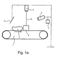
- FIG. 1a and 1b a perspective view of the apparatus according to the present invention is shown, wherein an object 2 is being conveyed by means of conveyor belt 1 in a direction given by the arrow.
- Illumination source 5 casts a planar beam of light 10 across the conveyer belt and orthogonal to the direction of movement and further on the two side reflecting means 4, preferably mirrors.
- the illuminating source may be a laser and a cylindrical lens or vibrating mirror for producing a planar beam of light.
- a capturing means 6 such as a CCD matrix sensor is situated above the conveyor belt and receives a view of practically the entire perimeter through the two reflecting side mirrors, which in this embodiment are left-and right mirrors as shown in Fig. 1b and the back rear window 3.
- the orientation of the sensor and the left-and right mirrors is such that that the sensor captures the following four views:
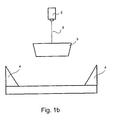
- Fig.2 shows an example of an cylindrical shaped object 9 being conveyed from the viewpoint of the capturing means at one instant of time. Shown is the reflected image from the first two side mirrors 4, a right side image 11 and left side image 12, the rear back mirror image 13 and reflection from the object 14 as the object enters the planar beam of light 10.
- the side mirrors serve the purpose that they reflect the illumination line to the sides of the object and to underneath segments that are elevated from the conveyor belt surface and give therefore the sensor a view of these areas.
- Fig.2 shows, half the perimeter of the cylinder is visible, and the other half is detected by the side mirrors. Therefore, the light that hits the surface of the cylinder that is in line of sight from the viewpoint of the capturing means is reflected to the sensor. If on the other hand a part of the surface would not be reflected to the sensor, the use of the back mirror would be preferable.
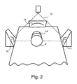
- Fig. 3 shows an image domain, wherein the images from each reflecting means are assigned to a certain domains.
- the image 12 of the left mirror is assigned to one domain 15
- the image 11 of the right mirror is assigned to another domain 17
- the image 13 of the back mirror is assigned to the third domain 16
- the image 14 that is reflected to the sensor is assigned to the fourth domain 18.
- Each of these captured images comprises scan elements, i.e. pixels, based on a reflection of the planar light beam from the object and the mirrors..
- These scan elements in each domain have a coordinate in accordance with the domain that it is assigned to.
- the transformation procedure can comprise translational, rotational and/or scaling transformation of the matrix elements from the image domain into the object domain.
- the transformation from the image domain to the mutual object domain can be based on a database, wherein the coordinates of the picture scan elements in the image domain are given new coordinates in accordance with said transformations to the mutual object domain.
- the transformation procedure may also comprise a transformation from the image domains into the object domain without using a database, wherein the transformation can be based on the orientation of the reference points relative to the capturing means. For this object, the back rear mirror was not essential because of the reflection toward the capturing means.
- endpoints in fourth domain 18 after transformation are obtained and shortest distance to each said endpoint to each transformed endpoints in domain 15 and 17 define matching points and are used to connect the object together.
- the area for the object can be calculated by summation after these matching points have been found.
- the area determination is preferably based on summing up the area of one pixel, which is the width multiplied by the height of the pixel. Volume is therefore obtained by multiplying said area with the image thickness, which depends on the resolution.
- This image processing is repeated while the object is being subjected to the planar beam of light. Based on a plurality of such two dimensional images in the object domain, a three dimensional image is defined. By varying the processing rate the resolution of the three dimensional image is varied. High processing rate would lead to high resolution of the images and conversely.
- Fig. 4 shows an example of an conical object 21 being conveyed, wherein the end with the larger radius is facing the sensor. Shown is the reflected image from the left side mirror 23, the right side mirror 22 and the back mirror 24.
- Fig. 5 image domains from each reflecting means are shown. As before the image of the left mirror 23 is assigned to one domain 15, the image of the right mirror 22 is assigned to another domain 17, the image of the back mirror 24 is assigned to the third domain but due to the conical shape of the object the image domain of the direct view to the sensor 18 is empty, where we have assumed that no reflection from the surface is detected directly by the sensor. In this case the role of the back mirror is necessary in order to enable a definition of the two dimensional image in the object domain.
- the transformation procedure 25 from the image domains to the mutual object domain would therefore define the object. By repeating the image processing a plurality of two dimensional image in the object domain would define a three dimensional image.
- Fig. 6 shows a side view of the conical object 21 shown in Fig. 5 as it is being conveyed 1.
- the processing start. No light is reflected from the object to the sensor 6.
- the surface of the object can be detected from the reflection from the surface from the object to the back mirror 3, and from the back mirror to the sensor. Therefore half the perimeter of the object is detected by the back mirror and the other half by the side mirrors 4.
- a processor 7 is used to transforme the data from the image domains to a mutual object domains.
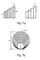
- Fig. 7 a) and 7 b ) shows two perspective views for a conical shaped object after repeating the image processing of the two dimensional image while the object enters the planar beam of light.
- the result is a number of cylinders wherein the radius increases in discrete steps from the lowest diameter 37 up to the highest diameter 36.
- Fig. 7a ) shows an example of two different processing speeds, which is reflected in different height of the cylinder 32, 31. As the processing speed is increased, the accuracy of the volume determination of the object increases 28 and the height of each cylinder decreases 32, compared to lower processing speed, where the height of each cylinder is larger 31.
- FIG. 7 b) shows a number of cylinders with diameters D i and height d i , wherein the height d i (32,31) is directly related to the processing speed. Accordingly, the diameter of the first circle 37 corresponds to the minimum height in Fig. 7 a) 37 and the radius of the largest circle 36 corresponds to the maximum height.
- Fig. 8 shows a Flow Diagram from an object entering a planar beam of light until the it leaves the planar beam of light.
- the amount of processing is minimal and thus the scan frequency can be maximal.
- the image may consist of a straight line until the object enters the light.
- the processing speed increases and the scanning frequency can be decreased to a set value as the capturing of two dimensional images in a image domain starts 38.
- a processor transforms the data from image domain where the images are captured to an object domain 39 which forms a two dimensional image. This is repeated while the object enters the light 40. Soon as the object does not subject the light, a complete 3D image in the object domain can be constructed.
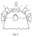
- Fig. 9 shows an example of the most preferably embodiment of the invention where two additional second side mirrors 42,43 have been added to the two first side mirrors 22,23.
- the distance between the two second side mirrors is shorter than between the first two side mirror.
- the viewing angle of the capturing means is lowered and the efficiency in the performance in the capturing means is increased.
- the capturing means can be positioned closer to the reflecting means and the light source.
- the two second side mirrors will furthermore be positioned so that the side view image of the object from the two first side mirrors is viewed in the two second side mirrors 44,45, from which it is captured by the capturing means.
Landscapes
- Engineering & Computer Science (AREA)
- Physics & Mathematics (AREA)
- General Physics & Mathematics (AREA)
- Computer Vision & Pattern Recognition (AREA)
- Multimedia (AREA)
- Theoretical Computer Science (AREA)
- Fluid Mechanics (AREA)
- Signal Processing (AREA)
- Length Measuring Devices By Optical Means (AREA)
Abstract
Claims (21)
- Procédé pour déterminer une image tridimensionnelle d'un objet en mouvement (2), le procédé comprenant les étapes consistant, de manière répétitive, à :a) capturer une image bidimensionnelle de l'objet (2) à l'aide d'un moyen de capture (6), l'image capturée comprenant un élément de balayage basé sur une réflexion d'un faisceau de lumière plan (10) provenant de l' obj et (2) et un élément de balayage basé sur une réflexion du faisceau de lumière plan (10) provenant de l'objet, en outre réfléchi par une pluralité de moyens de réflexion,b) diviser l'image bidimensionnelle en au moins deux domaines d'image, un domaine d'image (15) comprenant une réflexion du faisceau de lumière plan (10) par l'objet (2) et au moins un domaine d'image (15) comprenant une réflexion du faisceau de lumière plan (10) par au moins un desdits moyens de réflexion (4), etc) transformer les domaines d'image en un domaine d'objet mutuel bidimensionnel au moyen d'une procédure de transformation,tandis que l'objet (2) est soumis au faisceau de lumière plan (10) et, sur la base de la pluralité des deux images bidimensionnelles dans le domaine d'objet, une image tridimensionnelle est définie,
le moyen de réflexion (4) comprenant au moins un miroir latéral et au moins un miroir arrière (24) adaptés pour voir des parties d'image latérale et supérieure de l'objet (2). - Procédé selon la revendication 1, la transformation des domaines d'image en un domaine d'objet mutuel comprenant de transformer chaque élément de balayage dans le domaine d'image avec une fonction de transformation adaptée pour transformer ce domaine d'image spécifique en le domaine d'objet mutuel.
- Procédé selon la revendication 1 ou la revendication 2, la fonction de transformation comprenant une transformation de translation.
- Procédé selon l'une quelconque des revendications précédentes, la fonction de transformation comprenant une transformation de rotation.
- Procédé selon l'une quelconque des revendications précédentes, la fonction de transformation comprenant une transformation de mise à l'échelle.
- Procédé selon l'une quelconque des revendications précédentes, le domaine d'objet mutuel donnant les coordonnées du profil transversal bidimensionnel de l'image.
- Procédé selon l'une quelconque des revendications précédentes, la transformation à partir des domaines d'image en domaine d'objet mutuel étant basée sur une base de données dans laquelle les coordonnées des éléments de balayage d'image dans les domaines d'image se voient attribuer de nouvelles coordonnées conformément auxdites transformations en le domaine d'objet mutuel.
- Procédé selon l'une quelconque des revendications précédentes, le faisceau de lumière plan (10) étant situé au-dessus de l'objet en mouvement (2) et le plan du faisceau de lumière (10) étant perpendiculaire à la direction de mouvement de l'objet (2).
- Procédé selon la revendication 1, l'au moins un miroir arrière (24) étant un miroir arrière unique situé du côté opposé au moyen de capture (6) et au-dessus de l'objet en mouvement.
- Procédé selon l'une quelconque des revendications précédentes, le côté réfléchissant d'au moins un miroir arrière (24) étant positionné perpendiculairement à la direction de déplacement de l'objet (2).
- Procédé selon l'une quelconque des revendications précédentes, l'au moins un miroir latéral (22, 23) étant positionné le long de la direction de déplacement de l'objet (2) et dans le plan du faisceau de lumière plan (10) de manière à ce que la lumière soit réfléchie depuis le miroir vers l'objet (2) et retour vers le miroir, permettant, par ce moyen à l'image de visualisation latérale de l'objet (2) d'être détectable, laquelle n'étant sinon pas détectable par le moyen de capture (6).
- Procédé selon l'une quelconque des revendications précédentes, l'au moins un miroir latéral (22, 23) étant positionné parallèlement à la direction de déplacement de l'objet (2).
- Procédé selon l'une quelconque des revendications précédentes, la source de lumière, le moyen de capture, ledit au moins un miroir latéral (22, 23) et ledit au moins un miroir arrière (24) étant assemblés et montés en une unité unique dans une position fixée, ledit au moins un premier miroir latéral (22, 23) étant situé entre le moyen de capture (6) et ledit au moins un miroir arrière (24).
- Procédé selon l'une quelconque des revendications précédentes, le moyen de déplacement étant une bande convoyeuse (1).
- Procédé selon l'une quelconque des revendications précédentes, la fréquence de capture d'une image bidimensionnelle étant contrôlée par le moyen de capture (6) de telle manière que lorsqu'aucune image de profil n'est détectée, le traitement d'image est minimal et la fréquence de balayage est maximale.
- Procédé selon l'une quelconque des revendications précédentes, le volume total de l'objet (2) étant calculé à partir de l'image tridimensionnelle.
- Procédé selon l'une quelconque des revendications précédentes, la distribution massique étant déterminée en pondérant l'objet (2) et en utilisant les informations relatives au volume total de l'objet (2).
- Procédé selon l'une quelconque des revendications précédentes, la distribution massique étant utilisée pour couper l'objet (2).
- Procédé selon l'une quelconque des revendications précédentes, la pureté de la ligne de contour obtenue à partir de l'image de profil bidimensionnelle de l'objet (2) étant utilisée comme un indicateur de la rugosité de l'objet.
- Procédé selon l'une quelconque des revendications précédentes, le moyen de capture (6) comprenant un moyen pour capturer la couleur, et la couleur étant utilisée comme un indicateur de teneur en graisse et/ou de teneur en muscle et/ou de teneur en eau et/ou de composition chimique.
- Appareil pour déterminer une image tridimensionnelle d'un objet en mouvement, l'appareil comprenant :un convoyeur (1) pour convoyer l'objet,une pluralité de moyens de réflexion (4) comprenant au moins un miroir latéral (22, 23),un moyen de capture (6) pour capturer une image bidimensionnelle de l'objet (2) tandis que l'objet (2) est convoyé, l'image capturée comprenant un élément de balayage basé sur une réflexion d'un faisceau de lumière plan (10) provenant de l'objet (2) et un élément de balayage basé sur une réflexion du faisceau de lumière plan (10) provenant de l'objet, en outre réfléchi par le moyen de réflexion (4),un système informatique pour stocker les images capturées et pour diviser l'image bidimensionnelle en au moins deux domaines d'image, un domaine d'image comprenant une réflexion du faisceau de lumière plan (10) provenant de l'objet (2), et au moins un domaine d'image comprend une réflexion du faisceau de lumière plan (10) provenant d'au moins un desdits moyens de réflexion (4), et pour transformer les domaines d'image en un domaine d'objet mutuel bidimensionnel au moyen d'une procédure de transformation tandis que l'objet (2) est soumis au faisceau de lumière plan (10) et, sur la base de la pluralité des deux images bidimensionnelles dans le domaine d'objet, pour générer une image tridimensionnelle de l'objet,caractérisé en ce que le moyen de réflexion (4) comprend au moins un miroir arrière (24) adapté pour voir des parties d'image latérale et supérieure de l'objet (2).
Applications Claiming Priority (5)
| Application Number | Priority Date | Filing Date | Title |
|---|---|---|---|
| IS583801 | 2001-02-01 | ||
| IS5838 | 2001-02-01 | ||
| US26587601P | 2001-02-05 | 2001-02-05 | |
| US265876P | 2001-02-05 | ||
| PCT/IS2002/000004 WO2002061368A2 (fr) | 2001-02-01 | 2002-02-01 | Vision par miroir laser |
Publications (3)
| Publication Number | Publication Date |
|---|---|
| EP1368614A2 EP1368614A2 (fr) | 2003-12-10 |
| EP1368614B1 true EP1368614B1 (fr) | 2012-06-13 |
| EP1368614B8 EP1368614B8 (fr) | 2012-07-18 |
Family
ID=26324938
Family Applications (1)
| Application Number | Title | Priority Date | Filing Date |
|---|---|---|---|
| EP02716300A Expired - Lifetime EP1368614B8 (fr) | 2001-02-01 | 2002-02-01 | Vision par miroir laser |
Country Status (5)
| Country | Link |
|---|---|
| US (1) | US7205529B2 (fr) |
| EP (1) | EP1368614B8 (fr) |
| AU (1) | AU2002226671B2 (fr) |
| IS (1) | IS6900A (fr) |
| WO (1) | WO2002061368A2 (fr) |
Families Citing this family (89)
| Publication number | Priority date | Publication date | Assignee | Title |
|---|---|---|---|---|
| US20020014533A1 (en) * | 1995-12-18 | 2002-02-07 | Xiaxun Zhu | Automated object dimensioning system employing contour tracing, vertice detection, and forner point detection and reduction methods on 2-d range data maps |
| CN1142414C (zh) * | 2002-08-16 | 2004-03-17 | 清华大学 | 在线测量物料重量的装置 |
| GB0419059D0 (en) * | 2004-08-26 | 2004-09-29 | Ici Plc | Sediment assessment |
| WO2006048857A1 (fr) * | 2004-11-01 | 2006-05-11 | Cognitens Ltd. | Procede et systeme de mesure de contour optique |
| DE102006031906B4 (de) * | 2006-07-07 | 2009-07-30 | Kappner, Helmut A. | Vorrichtung zum optisch umseitigen Prüfen von Werkstücken |
| DE102006042311B4 (de) * | 2006-09-06 | 2013-12-05 | 3D-Shape Gmbh | Dreidimensionale Vermessung von Objekten in einem erweiterten Winkelbereich |
| EP1901030A3 (fr) * | 2006-09-13 | 2010-06-23 | Micro-Epsilon Optronic GmbH | Agencement de mesure et procédé de détection de la surface d'objets |
| US8189962B2 (en) * | 2006-12-19 | 2012-05-29 | Hitachi Kokusai Electric Inc. | Image processing apparatus |
| DE102008002776A1 (de) * | 2008-02-19 | 2009-09-03 | Banss Schlacht- und Fördertechnik GmbH | Verfahren zum automatisierten Bearbeiten von Schlachttieren |
| DE102008024559A1 (de) * | 2008-05-21 | 2009-11-26 | Technische Universität Braunschweig Carolo-Wilhelmina | 3D-Geometrieerfassungsvorrichtung |
| CN105303699B (zh) | 2008-10-02 | 2018-10-09 | 埃科亚特姆公司 | 针对设备的二手市场和自动售货系统 |
| US9881284B2 (en) | 2008-10-02 | 2018-01-30 | ecoATM, Inc. | Mini-kiosk for recycling electronic devices |
| US10853873B2 (en) | 2008-10-02 | 2020-12-01 | Ecoatm, Llc | Kiosks for evaluating and purchasing used electronic devices and related technology |
| US20130124426A1 (en) * | 2008-10-02 | 2013-05-16 | ecoATM, Inc. | Method And Apparatus For Recycling Electronic Devices |
| US11010841B2 (en) | 2008-10-02 | 2021-05-18 | Ecoatm, Llc | Kiosk for recycling electronic devices |
| US7881965B2 (en) | 2008-10-02 | 2011-02-01 | ecoATM, Inc. | Secondary market and vending system for devices |
| US8908995B2 (en) * | 2009-01-12 | 2014-12-09 | Intermec Ip Corp. | Semi-automatic dimensioning with imager on a portable device |
| US8643717B2 (en) * | 2009-03-04 | 2014-02-04 | Hand Held Products, Inc. | System and method for measuring irregular objects with a single camera |
| DE102009038746B3 (de) * | 2009-08-27 | 2011-04-14 | Airbus Operations Gmbh | Verfahren und Vorrichtung zur Qualitätsprüfung eines umgeformten thermoplastischen faserverstärkten Kunststoffbauteils |
| JP5563372B2 (ja) * | 2010-05-20 | 2014-07-30 | 第一実業ビスウィル株式会社 | 外観検査装置 |
| CA3210819A1 (fr) | 2011-04-06 | 2012-10-11 | Ecoatm, Llc | Procede et kiosque pour le recyclage de dispositifs electroniques |
| JP5686058B2 (ja) * | 2011-07-04 | 2015-03-18 | 株式会社ダイフク | 農産物の体積測定装置 |
| DE102012102649A1 (de) | 2012-03-27 | 2013-10-02 | Uwe Reifenhäuser | Verfahren und Vorrichtung zum gewichtsgenauen Schneiden eines Lebensmittelstranges |
| US9779546B2 (en) | 2012-05-04 | 2017-10-03 | Intermec Ip Corp. | Volume dimensioning systems and methods |
| US10007858B2 (en) | 2012-05-15 | 2018-06-26 | Honeywell International Inc. | Terminals and methods for dimensioning objects |
| US10321127B2 (en) | 2012-08-20 | 2019-06-11 | Intermec Ip Corp. | Volume dimensioning system calibration systems and methods |
| US9939259B2 (en) | 2012-10-04 | 2018-04-10 | Hand Held Products, Inc. | Measuring object dimensions using mobile computer |
| US20140104413A1 (en) | 2012-10-16 | 2014-04-17 | Hand Held Products, Inc. | Integrated dimensioning and weighing system |
| US10228452B2 (en) | 2013-06-07 | 2019-03-12 | Hand Held Products, Inc. | Method of error correction for 3D imaging device |
| US9823059B2 (en) | 2014-08-06 | 2017-11-21 | Hand Held Products, Inc. | Dimensioning system with guided alignment |
| US10401411B2 (en) | 2014-09-29 | 2019-09-03 | Ecoatm, Llc | Maintaining sets of cable components used for wired analysis, charging, or other interaction with portable electronic devices |
| EP3859697A1 (fr) | 2014-10-02 | 2021-08-04 | ecoATM, LLC | Application pour l'évaluation de dispositif et d'autres procédés associés au recyclage de dispositif |
| WO2016053378A1 (fr) | 2014-10-02 | 2016-04-07 | ecoATM, Inc. | Kiosque activé sans fil pour le recyclage de dispositifs de consommateurs |
| US10445708B2 (en) | 2014-10-03 | 2019-10-15 | Ecoatm, Llc | System for electrically testing mobile devices at a consumer-operated kiosk, and associated devices and methods |
| US10775165B2 (en) | 2014-10-10 | 2020-09-15 | Hand Held Products, Inc. | Methods for improving the accuracy of dimensioning-system measurements |
| US9779276B2 (en) | 2014-10-10 | 2017-10-03 | Hand Held Products, Inc. | Depth sensor based auto-focus system for an indicia scanner |
| US10810715B2 (en) | 2014-10-10 | 2020-10-20 | Hand Held Products, Inc | System and method for picking validation |
| US10060729B2 (en) | 2014-10-21 | 2018-08-28 | Hand Held Products, Inc. | Handheld dimensioner with data-quality indication |
| US9897434B2 (en) | 2014-10-21 | 2018-02-20 | Hand Held Products, Inc. | Handheld dimensioning system with measurement-conformance feedback |
| US9752864B2 (en) | 2014-10-21 | 2017-09-05 | Hand Held Products, Inc. | Handheld dimensioning system with feedback |
| US20170169401A1 (en) | 2015-12-11 | 2017-06-15 | ecoATM, Inc. | Systems and methods for recycling consumer electronic devices |
| WO2016069742A1 (fr) | 2014-10-31 | 2016-05-06 | ecoATM, Inc. | Procédés et systèmes pour faciliter des processus associés à des services d'assurance et/ou d'autres services pour dispositifs électroniques |
| WO2016069738A1 (fr) | 2014-10-31 | 2016-05-06 | ecoATM, Inc. | Systèmes et procédés pour recycler des dispositifs électroniques grand public |
| EP4560549A3 (fr) | 2014-11-06 | 2025-06-18 | ecoATM, LLC | Procédés et systèmes d'évaluation et de recyclage de dispositifs électroniques |
| US9341466B1 (en) | 2014-12-04 | 2016-05-17 | Xerox Corporation | Sheet height sensor using movable and stationary mirrors |
| WO2016094789A1 (fr) | 2014-12-12 | 2016-06-16 | ecoATM, Inc. | Systèmes et procédés pour le recyclage de dispositifs électroniques grand public |
| US9786101B2 (en) | 2015-05-19 | 2017-10-10 | Hand Held Products, Inc. | Evaluating image values |
| US10066982B2 (en) | 2015-06-16 | 2018-09-04 | Hand Held Products, Inc. | Calibrating a volume dimensioner |
| US20160377414A1 (en) | 2015-06-23 | 2016-12-29 | Hand Held Products, Inc. | Optical pattern projector |
| US9857167B2 (en) | 2015-06-23 | 2018-01-02 | Hand Held Products, Inc. | Dual-projector three-dimensional scanner |
| US9835486B2 (en) | 2015-07-07 | 2017-12-05 | Hand Held Products, Inc. | Mobile dimensioner apparatus for use in commerce |
| EP3396313B1 (fr) | 2015-07-15 | 2020-10-21 | Hand Held Products, Inc. | Méthode et dispositif de dimensionnement mobile avec précision dynamique compatible avec une norme nist |
| US20170017301A1 (en) | 2015-07-16 | 2017-01-19 | Hand Held Products, Inc. | Adjusting dimensioning results using augmented reality |
| US10094650B2 (en) | 2015-07-16 | 2018-10-09 | Hand Held Products, Inc. | Dimensioning and imaging items |
| US10318976B2 (en) * | 2015-07-28 | 2019-06-11 | Walmart Apollo, Llc | Methods for determining measurement data of an item |
| US10249030B2 (en) | 2015-10-30 | 2019-04-02 | Hand Held Products, Inc. | Image transformation for indicia reading |
| ITUB20155673A1 (it) * | 2015-11-18 | 2017-05-18 | Gd Spa | Unita di ispezione di un elemento allungato. |
| US10225544B2 (en) | 2015-11-19 | 2019-03-05 | Hand Held Products, Inc. | High resolution dot pattern |
| US10025314B2 (en) | 2016-01-27 | 2018-07-17 | Hand Held Products, Inc. | Vehicle positioning and object avoidance |
| US20170244904A1 (en) * | 2016-02-18 | 2017-08-24 | The Boeing Company | Optical monitoring system and method for imaging a component under test |
| DE102016205219A1 (de) * | 2016-03-30 | 2017-10-05 | Siemens Aktiengesellschaft | Mehr-Richtungs-Triangulations-Messsystem mit Verfahren |
| DE102016205245A1 (de) * | 2016-03-30 | 2017-10-05 | Siemens Aktiengesellschaft | Mehr-Richtungs-Triangulations-Messsystem mit Vorrichtung |
| US10127647B2 (en) | 2016-04-15 | 2018-11-13 | Ecoatm, Llc | Methods and systems for detecting cracks in electronic devices |
| US10339352B2 (en) | 2016-06-03 | 2019-07-02 | Hand Held Products, Inc. | Wearable metrological apparatus |
| US9885672B2 (en) | 2016-06-08 | 2018-02-06 | ecoATM, Inc. | Methods and systems for detecting screen covers on electronic devices |
| US9940721B2 (en) | 2016-06-10 | 2018-04-10 | Hand Held Products, Inc. | Scene change detection in a dimensioner |
| US10163216B2 (en) | 2016-06-15 | 2018-12-25 | Hand Held Products, Inc. | Automatic mode switching in a volume dimensioner |
| US10269110B2 (en) | 2016-06-28 | 2019-04-23 | Ecoatm, Llc | Methods and systems for detecting cracks in illuminated electronic device screens |
| US10909708B2 (en) | 2016-12-09 | 2021-02-02 | Hand Held Products, Inc. | Calibrating a dimensioner using ratios of measurable parameters of optic ally-perceptible geometric elements |
| TWI628428B (zh) * | 2016-12-16 | 2018-07-01 | 由田新技股份有限公司 | 多視角影像擷取裝置、及其多視角影像檢測設備 |
| US11047672B2 (en) | 2017-03-28 | 2021-06-29 | Hand Held Products, Inc. | System for optically dimensioning |
| US10733748B2 (en) | 2017-07-24 | 2020-08-04 | Hand Held Products, Inc. | Dual-pattern optical 3D dimensioning |
| US10584962B2 (en) | 2018-05-01 | 2020-03-10 | Hand Held Products, Inc | System and method for validating physical-item security |
| US12322259B2 (en) | 2018-12-19 | 2025-06-03 | Ecoatm, Llc | Systems and methods for vending and/or purchasing mobile phones and other electronic devices |
| KR102942007B1 (ko) | 2018-12-19 | 2026-03-19 | 에코에이티엠, 엘엘씨 | 이동 전화기 및 다른 전자 디바이스의 판매 및/또는 구매를 위한 시스템 및 방법 |
| CN109540241A (zh) * | 2019-01-22 | 2019-03-29 | 艾信智慧医疗科技发展(苏州)有限公司 | 体积测量系统及方法 |
| US11462868B2 (en) | 2019-02-12 | 2022-10-04 | Ecoatm, Llc | Connector carrier for electronic device kiosk |
| EP3924918B1 (fr) | 2019-02-12 | 2026-04-01 | ecoATM, LLC | Kiosque pour évaluer et acheter des dispositifs électroniques usagés |
| US11798250B2 (en) | 2019-02-18 | 2023-10-24 | Ecoatm, Llc | Neural network based physical condition evaluation of electronic devices, and associated systems and methods |
| US11639846B2 (en) | 2019-09-27 | 2023-05-02 | Honeywell International Inc. | Dual-pattern optical 3D dimensioning |
| JP2023508903A (ja) | 2019-12-18 | 2023-03-06 | エコエーティーエム, エルエルシー | 携帯電話および他の電子デバイスを販売および/または買取するためのシステムならびに方法 |
| US11922467B2 (en) | 2020-08-17 | 2024-03-05 | ecoATM, Inc. | Evaluating an electronic device using optical character recognition |
| EP4197083B1 (fr) | 2020-08-17 | 2024-10-09 | ecoATM, LLC | Support de connecteur de kiosque de dispositifs électroniques |
| WO2022040667A1 (fr) | 2020-08-17 | 2022-02-24 | Ecoatm, Llc | Évaluation d'un dispositif électronique à l'aide d'un chargeur sans fil |
| US12271929B2 (en) | 2020-08-17 | 2025-04-08 | Ecoatm Llc | Evaluating an electronic device using a wireless charger |
| EP4738801A2 (fr) | 2020-08-25 | 2026-05-06 | ecoATM, LLC | Évaluation et recyclage de dispositifs électroniques |
| US12462635B2 (en) | 2021-07-09 | 2025-11-04 | Ecoatm, Llc | Identifying electronic devices using temporally changing information |
| JP2023135304A (ja) * | 2022-03-15 | 2023-09-28 | 第一実業ビスウィル株式会社 | 環状製品の外観検査装置 |
| FI131433B1 (fi) * | 2023-10-20 | 2025-04-22 | Teknosavo Oy | Menetelmä kuitupuu- tai tukkinipun kiintotilavuuden määrittämiseksi |
Family Cites Families (8)
| Publication number | Priority date | Publication date | Assignee | Title |
|---|---|---|---|---|
| DE3528047A1 (de) * | 1985-08-05 | 1987-02-05 | Bbc Brown Boveri & Cie | Verfahren zum orten von unbekannten gegenstaenden |
| JPH0799326B2 (ja) * | 1986-08-30 | 1995-10-25 | 株式会社マキ製作所 | 球塊状物品の外観検査方法と装置 |
| DE3805455A1 (de) | 1988-02-22 | 1989-08-31 | Linck Masch Gatterlinck | Vorrichtung zum fotoelektrischen abtasten und/oder vermessen von holzerzeugnissen |
| IS1666B (is) | 1991-02-19 | 1997-11-14 | Marel Hf | Aðferð og búnaður til ákvörðunar rúmmáls, forms og þyngdar fisks eða annarra hluta |
| JP2720920B2 (ja) * | 1991-03-11 | 1998-03-04 | 工業技術院長 | 画像処理システムにおける実写画像とコンピュータグラフィックスの合成方法 |
| DE19514692C2 (de) | 1995-04-13 | 1998-12-17 | Sicon Spectroscopic Instr Gmbh | Optische Koordinaten-Meßmaschine zur berührungslosen, dreidimensionalen Vermessung von Werkstücken auf einer Meßfläche |
| US5689629A (en) * | 1995-12-12 | 1997-11-18 | The Regents Of The University Of California | Iterative optimizing quantization method for reconstructing three-dimensional images from a limited number of views |
| US5825068A (en) * | 1997-03-17 | 1998-10-20 | Integrated Device Technology, Inc. | Integrated circuits that include a barrier layer reducing hydrogen diffusion into a polysilicon resistor |
-
2002
- 2002-02-01 AU AU2002226671A patent/AU2002226671B2/en not_active Ceased
- 2002-02-01 WO PCT/IS2002/000004 patent/WO2002061368A2/fr not_active Ceased
- 2002-02-01 EP EP02716300A patent/EP1368614B8/fr not_active Expired - Lifetime
- 2002-02-01 US US10/470,775 patent/US7205529B2/en not_active Expired - Fee Related
-
2003
- 2003-07-30 IS IS6900A patent/IS6900A/is unknown
Also Published As
| Publication number | Publication date |
|---|---|
| EP1368614A2 (fr) | 2003-12-10 |
| WO2002061368A8 (fr) | 2004-04-29 |
| WO2002061368A2 (fr) | 2002-08-08 |
| US7205529B2 (en) | 2007-04-17 |
| US20040114153A1 (en) | 2004-06-17 |
| EP1368614B8 (fr) | 2012-07-18 |
| WO2002061368A3 (fr) | 2002-10-03 |
| AU2002226671B2 (en) | 2006-08-31 |
| IS6900A (is) | 2003-07-30 |
Similar Documents
| Publication | Publication Date | Title |
|---|---|---|
| EP1368614B1 (fr) | Vision par miroir laser | |
| AU2002226671A1 (en) | Method and apparatus for determining a three dimensional image of a moving object by means of light | |
| US20170307363A1 (en) | 3d scanner using merged partial images | |
| US6549288B1 (en) | Structured-light, triangulation-based three-dimensional digitizer | |
| US6974964B1 (en) | Method and apparatus for three-dimensional surface scanning and measurement of a moving object | |
| US7271377B2 (en) | Calibration ring for developing and aligning view dependent image maps with 3-D surface data | |
| EP2195608B1 (fr) | Système et procédé de mesure de forme d'objets par mesure de surface d'images multiples | |
| US8483477B2 (en) | Method of constructing a digital image of a three-dimensional (3D) surface using a mask | |
| US20110074929A1 (en) | Auto-referenced sensing device for three-dimensional scanning | |
| US5889582A (en) | Image-directed active range finding system | |
| US20070223009A1 (en) | Apparatus and method for measuring structural parts | |
| CN102713671A (zh) | 点群数据处理装置、点群数据处理方法和点群数据处理程序 | |
| IL138414A (en) | Apparatus and method for optically measuring an object surface contour | |
| JPH10507003A (ja) | 寸法測定システム | |
| EP1459035B1 (fr) | Procede pour determiner des points correspondants dans une methode de mesure tridimensionnelle stereoscopique | |
| US7620235B2 (en) | Device for scanning three-dimensional objects | |
| US11727635B2 (en) | Hybrid photogrammetry | |
| JPH06147863A (ja) | 曲げ加工機における曲げ角度検出装置 | |
| US6927864B2 (en) | Method and system for determining dimensions of optically recognizable features | |
| Sansoni et al. | A three-dimensional imaging system for industrial applications with improved flexibility and robustness | |
| Johannesson | Active Range Imaging 2 | |
| ES2389495T3 (es) | Visión por espejo láser | |
| Singh et al. | Digital photogrammetry for automatic close range measurement of textureless and featureless objects | |
| JPS5850417A (ja) | 距離測定方式 | |
| Clark et al. | Depth Sensing by Variable Baseline Triangulation. |
Legal Events
| Date | Code | Title | Description |
|---|---|---|---|
| PUAI | Public reference made under article 153(3) epc to a published international application that has entered the european phase |
Free format text: ORIGINAL CODE: 0009012 |
|
| 17P | Request for examination filed |
Effective date: 20030826 |
|
| AK | Designated contracting states |
Kind code of ref document: A2 Designated state(s): AT BE CH CY DE DK ES FI FR GB GR IE IT LI LU MC NL PT SE TR |
|
| AX | Request for extension of the european patent |
Extension state: AL LT LV MK RO SI |
|
| 17Q | First examination report despatched |
Effective date: 20090423 |
|
| REG | Reference to a national code |
Ref country code: DE Ref legal event code: R079 Ref document number: 60243113 Country of ref document: DE Free format text: PREVIOUS MAIN CLASS: G01B0011020000 Ipc: G01B0011000000 |
|
| GRAP | Despatch of communication of intention to grant a patent |
Free format text: ORIGINAL CODE: EPIDOSNIGR1 |
|
| GRAC | Information related to communication of intention to grant a patent modified |
Free format text: ORIGINAL CODE: EPIDOSCIGR1 |
|
| RIC1 | Information provided on ipc code assigned before grant |
Ipc: G06K 9/00 20060101ALI20111207BHEP Ipc: G01B 11/25 20060101ALI20111207BHEP Ipc: H04N 13/02 20060101ALI20111207BHEP Ipc: G06T 7/00 20060101ALI20111207BHEP Ipc: G01B 11/00 20060101AFI20111207BHEP Ipc: G01F 17/00 20060101ALI20111207BHEP |
|
| GRAS | Grant fee paid |
Free format text: ORIGINAL CODE: EPIDOSNIGR3 |
|
| GRAA | (expected) grant |
Free format text: ORIGINAL CODE: 0009210 |
|
| AK | Designated contracting states |
Kind code of ref document: B1 Designated state(s): AT BE CH CY DE DK ES FI FR GB GR IE IT LI LU MC NL PT SE TR |
|
| AX | Request for extension of the european patent |
Extension state: AL LT LV MK RO SI |
|
| REG | Reference to a national code |
Ref country code: GB Ref legal event code: FG4D |
|
| REG | Reference to a national code |
Ref country code: CH Ref legal event code: EP Ref country code: AT Ref legal event code: REF Ref document number: 562183 Country of ref document: AT Kind code of ref document: T Effective date: 20120615 |
|
| RAP2 | Party data changed (patent owner data changed or rights of a patent transferred) |
Owner name: MAREL HF. |
|
| REG | Reference to a national code |
Ref country code: IE Ref legal event code: FG4D |
|
| REG | Reference to a national code |
Ref country code: DE Ref legal event code: R096 Ref document number: 60243113 Country of ref document: DE Effective date: 20120802 |
|
| REG | Reference to a national code |
Ref country code: DK Ref legal event code: T3 |
|
| REG | Reference to a national code |
Ref country code: NL Ref legal event code: VDEP Effective date: 20120613 |
|
| REG | Reference to a national code |
Ref country code: ES Ref legal event code: FG2A Ref document number: 2389495 Country of ref document: ES Kind code of ref document: T3 Effective date: 20121026 |
|
| PG25 | Lapsed in a contracting state [announced via postgrant information from national office to epo] |
Ref country code: CY Free format text: LAPSE BECAUSE OF FAILURE TO SUBMIT A TRANSLATION OF THE DESCRIPTION OR TO PAY THE FEE WITHIN THE PRESCRIBED TIME-LIMIT Effective date: 20120613 Ref country code: SE Free format text: LAPSE BECAUSE OF FAILURE TO SUBMIT A TRANSLATION OF THE DESCRIPTION OR TO PAY THE FEE WITHIN THE PRESCRIBED TIME-LIMIT Effective date: 20120613 Ref country code: FI Free format text: LAPSE BECAUSE OF FAILURE TO SUBMIT A TRANSLATION OF THE DESCRIPTION OR TO PAY THE FEE WITHIN THE PRESCRIBED TIME-LIMIT Effective date: 20120613 |
|
| REG | Reference to a national code |
Ref country code: AT Ref legal event code: MK05 Ref document number: 562183 Country of ref document: AT Kind code of ref document: T Effective date: 20120613 |
|
| REG | Reference to a national code |
Ref country code: LT Ref legal event code: MG9D Effective date: 20120613 |
|
| PG25 | Lapsed in a contracting state [announced via postgrant information from national office to epo] |
Ref country code: GR Free format text: LAPSE BECAUSE OF FAILURE TO SUBMIT A TRANSLATION OF THE DESCRIPTION OR TO PAY THE FEE WITHIN THE PRESCRIBED TIME-LIMIT Effective date: 20120914 |
|
| PG25 | Lapsed in a contracting state [announced via postgrant information from national office to epo] |
Ref country code: AT Free format text: LAPSE BECAUSE OF FAILURE TO SUBMIT A TRANSLATION OF THE DESCRIPTION OR TO PAY THE FEE WITHIN THE PRESCRIBED TIME-LIMIT Effective date: 20120613 |
|
| PG25 | Lapsed in a contracting state [announced via postgrant information from national office to epo] |
Ref country code: PT Free format text: LAPSE BECAUSE OF FAILURE TO SUBMIT A TRANSLATION OF THE DESCRIPTION OR TO PAY THE FEE WITHIN THE PRESCRIBED TIME-LIMIT Effective date: 20121015 |
|
| PG25 | Lapsed in a contracting state [announced via postgrant information from national office to epo] |
Ref country code: NL Free format text: LAPSE BECAUSE OF FAILURE TO SUBMIT A TRANSLATION OF THE DESCRIPTION OR TO PAY THE FEE WITHIN THE PRESCRIBED TIME-LIMIT Effective date: 20120613 |
|
| PLBE | No opposition filed within time limit |
Free format text: ORIGINAL CODE: 0009261 |
|
| STAA | Information on the status of an ep patent application or granted ep patent |
Free format text: STATUS: NO OPPOSITION FILED WITHIN TIME LIMIT |
|
| 26N | No opposition filed |
Effective date: 20130314 |
|
| REG | Reference to a national code |
Ref country code: DE Ref legal event code: R097 Ref document number: 60243113 Country of ref document: DE Effective date: 20130314 |
|
| PG25 | Lapsed in a contracting state [announced via postgrant information from national office to epo] |
Ref country code: MC Free format text: LAPSE BECAUSE OF NON-PAYMENT OF DUE FEES Effective date: 20130228 |
|
| REG | Reference to a national code |
Ref country code: CH Ref legal event code: PL |
|
| PG25 | Lapsed in a contracting state [announced via postgrant information from national office to epo] |
Ref country code: CH Free format text: LAPSE BECAUSE OF NON-PAYMENT OF DUE FEES Effective date: 20130228 Ref country code: LI Free format text: LAPSE BECAUSE OF NON-PAYMENT OF DUE FEES Effective date: 20130228 |
|
| REG | Reference to a national code |
Ref country code: FR Ref legal event code: ST Effective date: 20131031 |
|
| REG | Reference to a national code |
Ref country code: IE Ref legal event code: MM4A |
|
| PG25 | Lapsed in a contracting state [announced via postgrant information from national office to epo] |
Ref country code: FR Free format text: LAPSE BECAUSE OF NON-PAYMENT OF DUE FEES Effective date: 20130228 Ref country code: IE Free format text: LAPSE BECAUSE OF NON-PAYMENT OF DUE FEES Effective date: 20130201 |
|
| PGFP | Annual fee paid to national office [announced via postgrant information from national office to epo] |
Ref country code: DK Payment date: 20150225 Year of fee payment: 14 Ref country code: DE Payment date: 20150223 Year of fee payment: 14 Ref country code: ES Payment date: 20150224 Year of fee payment: 14 Ref country code: IT Payment date: 20150223 Year of fee payment: 14 |
|
| PGFP | Annual fee paid to national office [announced via postgrant information from national office to epo] |
Ref country code: GB Payment date: 20150220 Year of fee payment: 14 |
|
| PG25 | Lapsed in a contracting state [announced via postgrant information from national office to epo] |
Ref country code: TR Free format text: LAPSE BECAUSE OF FAILURE TO SUBMIT A TRANSLATION OF THE DESCRIPTION OR TO PAY THE FEE WITHIN THE PRESCRIBED TIME-LIMIT Effective date: 20120613 |
|
| PGFP | Annual fee paid to national office [announced via postgrant information from national office to epo] |
Ref country code: BE Payment date: 20150217 Year of fee payment: 14 |
|
| PG25 | Lapsed in a contracting state [announced via postgrant information from national office to epo] |
Ref country code: LU Free format text: LAPSE BECAUSE OF NON-PAYMENT OF DUE FEES Effective date: 20130201 |
|
| PG25 | Lapsed in a contracting state [announced via postgrant information from national office to epo] |
Ref country code: BE Free format text: LAPSE BECAUSE OF NON-PAYMENT OF DUE FEES Effective date: 20160229 |
|
| REG | Reference to a national code |
Ref country code: DE Ref legal event code: R119 Ref document number: 60243113 Country of ref document: DE |
|
| REG | Reference to a national code |
Ref country code: DK Ref legal event code: EBP Effective date: 20160229 |
|
| GBPC | Gb: european patent ceased through non-payment of renewal fee |
Effective date: 20160201 |
|
| PG25 | Lapsed in a contracting state [announced via postgrant information from national office to epo] |
Ref country code: IT Free format text: LAPSE BECAUSE OF NON-PAYMENT OF DUE FEES Effective date: 20160201 |
|
| PG25 | Lapsed in a contracting state [announced via postgrant information from national office to epo] |
Ref country code: DK Free format text: LAPSE BECAUSE OF NON-PAYMENT OF DUE FEES Effective date: 20160229 Ref country code: GB Free format text: LAPSE BECAUSE OF NON-PAYMENT OF DUE FEES Effective date: 20160201 Ref country code: DE Free format text: LAPSE BECAUSE OF NON-PAYMENT OF DUE FEES Effective date: 20160901 |
|
| PG25 | Lapsed in a contracting state [announced via postgrant information from national office to epo] |
Ref country code: ES Free format text: LAPSE BECAUSE OF NON-PAYMENT OF DUE FEES Effective date: 20160202 |