EP1367664B1 - Graphithaltige Bipolarplatte mit Polypropylen als Polymerbinder - Google Patents
Graphithaltige Bipolarplatte mit Polypropylen als Polymerbinder Download PDFInfo
- Publication number
- EP1367664B1 EP1367664B1 EP03008343A EP03008343A EP1367664B1 EP 1367664 B1 EP1367664 B1 EP 1367664B1 EP 03008343 A EP03008343 A EP 03008343A EP 03008343 A EP03008343 A EP 03008343A EP 1367664 B1 EP1367664 B1 EP 1367664B1
- Authority
- EP
- European Patent Office
- Prior art keywords
- contact plate
- contact
- production
- plate
- plate according
- Prior art date
- Legal status (The legal status is an assumption and is not a legal conclusion. Google has not performed a legal analysis and makes no representation as to the accuracy of the status listed.)
- Expired - Lifetime
Links
- 239000004743 Polypropylene Substances 0.000 title claims description 5
- -1 polypropylene Polymers 0.000 title claims description 5
- 229920001155 polypropylene Polymers 0.000 title claims description 5
- 229920005596 polymer binder Polymers 0.000 title description 2
- 239000002491 polymer binding agent Substances 0.000 title description 2
- 238000000034 method Methods 0.000 claims abstract description 64
- 238000009826 distribution Methods 0.000 claims abstract description 43
- 239000002131 composite material Substances 0.000 claims abstract description 31
- 230000007704 transition Effects 0.000 claims abstract description 21
- 229910002804 graphite Inorganic materials 0.000 claims abstract description 14
- 239000010439 graphite Substances 0.000 claims abstract description 14
- 238000002347 injection Methods 0.000 claims abstract description 12
- 239000007924 injection Substances 0.000 claims abstract description 12
- 238000004519 manufacturing process Methods 0.000 claims description 41
- 239000004033 plastic Substances 0.000 claims description 38
- 229920003023 plastic Polymers 0.000 claims description 38
- 238000007789 sealing Methods 0.000 claims description 32
- 238000001746 injection moulding Methods 0.000 claims description 31
- 239000000463 material Substances 0.000 claims description 30
- OKTJSMMVPCPJKN-UHFFFAOYSA-N Carbon Chemical compound [C] OKTJSMMVPCPJKN-UHFFFAOYSA-N 0.000 claims description 14
- 239000012528 membrane Substances 0.000 claims description 13
- 239000003566 sealing material Substances 0.000 claims description 9
- 238000005516 engineering process Methods 0.000 claims description 6
- 239000012811 non-conductive material Substances 0.000 claims description 6
- 230000006835 compression Effects 0.000 claims description 4
- 238000007906 compression Methods 0.000 claims description 4
- 229910021383 artificial graphite Inorganic materials 0.000 claims description 3
- 239000010410 layer Substances 0.000 claims description 3
- 230000002093 peripheral effect Effects 0.000 claims description 3
- 229920001971 elastomer Polymers 0.000 claims description 2
- 239000000806 elastomer Substances 0.000 claims description 2
- 238000005488 sandblasting Methods 0.000 claims description 2
- 239000002344 surface layer Substances 0.000 claims description 2
- 238000005266 casting Methods 0.000 claims 3
- 210000002105 tongue Anatomy 0.000 claims 3
- 238000005304 joining Methods 0.000 claims 2
- 239000000109 continuous material Substances 0.000 claims 1
- 230000003116 impacting effect Effects 0.000 claims 1
- 239000000446 fuel Substances 0.000 abstract description 27
- 230000008569 process Effects 0.000 abstract description 10
- 238000001816 cooling Methods 0.000 abstract description 8
- 229920001169 thermoplastic Polymers 0.000 abstract description 8
- 239000005518 polymer electrolyte Substances 0.000 abstract 1
- 208000015943 Coeliac disease Diseases 0.000 description 11
- 239000002245 particle Substances 0.000 description 10
- 239000012429 reaction media Substances 0.000 description 9
- 239000002826 coolant Substances 0.000 description 8
- 239000007800 oxidant agent Substances 0.000 description 7
- 230000001590 oxidative effect Effects 0.000 description 6
- 239000004416 thermosoftening plastic Substances 0.000 description 6
- 238000005457 optimization Methods 0.000 description 5
- 229920001567 vinyl ester resin Polymers 0.000 description 5
- 238000013461 design Methods 0.000 description 4
- 239000000203 mixture Substances 0.000 description 4
- 125000000391 vinyl group Chemical group [H]C([*])=C([H])[H] 0.000 description 4
- OKKJLVBELUTLKV-UHFFFAOYSA-N Methanol Chemical compound OC OKKJLVBELUTLKV-UHFFFAOYSA-N 0.000 description 3
- 230000008901 benefit Effects 0.000 description 3
- 239000003054 catalyst Substances 0.000 description 3
- 238000006243 chemical reaction Methods 0.000 description 3
- 238000004132 cross linking Methods 0.000 description 3
- 239000003792 electrolyte Substances 0.000 description 3
- 239000003999 initiator Substances 0.000 description 3
- 229920000642 polymer Polymers 0.000 description 3
- 229920001187 thermosetting polymer Polymers 0.000 description 3
- IJGRMHOSHXDMSA-UHFFFAOYSA-N Atomic nitrogen Chemical compound N#N IJGRMHOSHXDMSA-UHFFFAOYSA-N 0.000 description 2
- 239000000853 adhesive Substances 0.000 description 2
- 230000001070 adhesive effect Effects 0.000 description 2
- 238000013459 approach Methods 0.000 description 2
- 239000011230 binding agent Substances 0.000 description 2
- 230000015572 biosynthetic process Effects 0.000 description 2
- 229910052799 carbon Inorganic materials 0.000 description 2
- 238000000748 compression moulding Methods 0.000 description 2
- 239000011231 conductive filler Substances 0.000 description 2
- 238000005260 corrosion Methods 0.000 description 2
- 230000007797 corrosion Effects 0.000 description 2
- 230000000694 effects Effects 0.000 description 2
- 230000007062 hydrolysis Effects 0.000 description 2
- 238000006460 hydrolysis reaction Methods 0.000 description 2
- 238000002156 mixing Methods 0.000 description 2
- 229920000728 polyester Polymers 0.000 description 2
- 238000003825 pressing Methods 0.000 description 2
- 238000004080 punching Methods 0.000 description 2
- 229920005989 resin Polymers 0.000 description 2
- 239000011347 resin Substances 0.000 description 2
- 239000000126 substance Substances 0.000 description 2
- KXGFMDJXCMQABM-UHFFFAOYSA-N 2-methoxy-6-methylphenol Chemical compound [CH]OC1=CC=CC([CH])=C1O KXGFMDJXCMQABM-UHFFFAOYSA-N 0.000 description 1
- UFHFLCQGNIYNRP-UHFFFAOYSA-N Hydrogen Chemical compound [H][H] UFHFLCQGNIYNRP-UHFFFAOYSA-N 0.000 description 1
- 239000002033 PVDF binder Substances 0.000 description 1
- 238000005299 abrasion Methods 0.000 description 1
- 230000001133 acceleration Effects 0.000 description 1
- 230000009471 action Effects 0.000 description 1
- 230000002411 adverse Effects 0.000 description 1
- 230000000712 assembly Effects 0.000 description 1
- 238000000429 assembly Methods 0.000 description 1
- QVGXLLKOCUKJST-UHFFFAOYSA-N atomic oxygen Chemical compound [O] QVGXLLKOCUKJST-UHFFFAOYSA-N 0.000 description 1
- 230000008859 change Effects 0.000 description 1
- 239000002322 conducting polymer Substances 0.000 description 1
- 229920001940 conductive polymer Polymers 0.000 description 1
- 239000004020 conductor Substances 0.000 description 1
- 238000007796 conventional method Methods 0.000 description 1
- 238000007334 copolymerization reaction Methods 0.000 description 1
- 238000006073 displacement reaction Methods 0.000 description 1
- 238000005553 drilling Methods 0.000 description 1
- 238000003411 electrode reaction Methods 0.000 description 1
- 238000006056 electrooxidation reaction Methods 0.000 description 1
- 125000000816 ethylene group Chemical group [H]C([H])([*:1])C([H])([H])[*:2] 0.000 description 1
- 239000000945 filler Substances 0.000 description 1
- 238000007731 hot pressing Methods 0.000 description 1
- 239000001257 hydrogen Substances 0.000 description 1
- 229910052739 hydrogen Inorganic materials 0.000 description 1
- 239000011256 inorganic filler Substances 0.000 description 1
- 229910003475 inorganic filler Inorganic materials 0.000 description 1
- 239000007788 liquid Substances 0.000 description 1
- 239000011244 liquid electrolyte Substances 0.000 description 1
- 230000013011 mating Effects 0.000 description 1
- 238000002844 melting Methods 0.000 description 1
- 230000008018 melting Effects 0.000 description 1
- 239000002184 metal Substances 0.000 description 1
- 238000010327 methods by industry Methods 0.000 description 1
- 238000003801 milling Methods 0.000 description 1
- 239000000178 monomer Substances 0.000 description 1
- 238000010137 moulding (plastic) Methods 0.000 description 1
- 229910052757 nitrogen Inorganic materials 0.000 description 1
- 239000001301 oxygen Substances 0.000 description 1
- 229910052760 oxygen Inorganic materials 0.000 description 1
- 239000000546 pharmaceutical excipient Substances 0.000 description 1
- 229920001568 phenolic resin Polymers 0.000 description 1
- 239000005011 phenolic resin Substances 0.000 description 1
- 229920005597 polymer membrane Polymers 0.000 description 1
- 229920002981 polyvinylidene fluoride Polymers 0.000 description 1
- 238000012805 post-processing Methods 0.000 description 1
- 239000000843 powder Substances 0.000 description 1
- 230000002265 prevention Effects 0.000 description 1
- 230000009467 reduction Effects 0.000 description 1
- 239000006254 rheological additive Substances 0.000 description 1
- 230000035945 sensitivity Effects 0.000 description 1
- 238000000926 separation method Methods 0.000 description 1
- 239000000243 solution Substances 0.000 description 1
- 230000000087 stabilizing effect Effects 0.000 description 1
- 239000007858 starting material Substances 0.000 description 1
- 238000010408 sweeping Methods 0.000 description 1
- 238000009827 uniform distribution Methods 0.000 description 1
- 229920006305 unsaturated polyester Polymers 0.000 description 1
Images


Classifications
-
- H—ELECTRICITY
- H01—ELECTRIC ELEMENTS
- H01M—PROCESSES OR MEANS, e.g. BATTERIES, FOR THE DIRECT CONVERSION OF CHEMICAL ENERGY INTO ELECTRICAL ENERGY
- H01M8/00—Fuel cells; Manufacture thereof
- H01M8/04—Auxiliary arrangements, e.g. for control of pressure or for circulation of fluids
- H01M8/04007—Auxiliary arrangements, e.g. for control of pressure or for circulation of fluids related to heat exchange
- H01M8/04067—Heat exchange or temperature measuring elements, thermal insulation, e.g. heat pipes, heat pumps, fins
- H01M8/04074—Heat exchange unit structures specially adapted for fuel cell
-
- B—PERFORMING OPERATIONS; TRANSPORTING
- B29—WORKING OF PLASTICS; WORKING OF SUBSTANCES IN A PLASTIC STATE IN GENERAL
- B29C—SHAPING OR JOINING OF PLASTICS; SHAPING OF MATERIAL IN A PLASTIC STATE, NOT OTHERWISE PROVIDED FOR; AFTER-TREATMENT OF THE SHAPED PRODUCTS, e.g. REPAIRING
- B29C45/00—Injection moulding, i.e. forcing the required volume of moulding material through a nozzle into a closed mould; Apparatus therefor
- B29C45/0013—Injection moulding, i.e. forcing the required volume of moulding material through a nozzle into a closed mould; Apparatus therefor using fillers dispersed in the moulding material, e.g. metal particles
-
- B—PERFORMING OPERATIONS; TRANSPORTING
- B29—WORKING OF PLASTICS; WORKING OF SUBSTANCES IN A PLASTIC STATE IN GENERAL
- B29C—SHAPING OR JOINING OF PLASTICS; SHAPING OF MATERIAL IN A PLASTIC STATE, NOT OTHERWISE PROVIDED FOR; AFTER-TREATMENT OF THE SHAPED PRODUCTS, e.g. REPAIRING
- B29C45/00—Injection moulding, i.e. forcing the required volume of moulding material through a nozzle into a closed mould; Apparatus therefor
- B29C45/17—Component parts, details or accessories; Auxiliary operations
- B29C45/26—Moulds
- B29C45/27—Sprue channels ; Runner channels or runner nozzles
- B29C45/2701—Details not specific to hot or cold runner channels
- B29C45/2708—Gates
-
- B—PERFORMING OPERATIONS; TRANSPORTING
- B29—WORKING OF PLASTICS; WORKING OF SUBSTANCES IN A PLASTIC STATE IN GENERAL
- B29C—SHAPING OR JOINING OF PLASTICS; SHAPING OF MATERIAL IN A PLASTIC STATE, NOT OTHERWISE PROVIDED FOR; AFTER-TREATMENT OF THE SHAPED PRODUCTS, e.g. REPAIRING
- B29C45/00—Injection moulding, i.e. forcing the required volume of moulding material through a nozzle into a closed mould; Apparatus therefor
- B29C45/17—Component parts, details or accessories; Auxiliary operations
- B29C45/40—Removing or ejecting moulded articles
-
- H—ELECTRICITY
- H01—ELECTRIC ELEMENTS
- H01M—PROCESSES OR MEANS, e.g. BATTERIES, FOR THE DIRECT CONVERSION OF CHEMICAL ENERGY INTO ELECTRICAL ENERGY
- H01M8/00—Fuel cells; Manufacture thereof
- H01M8/02—Details
- H01M8/0202—Collectors; Separators, e.g. bipolar separators; Interconnectors
- H01M8/0204—Non-porous and characterised by the material
- H01M8/0213—Gas-impermeable carbon-containing materials
-
- H—ELECTRICITY
- H01—ELECTRIC ELEMENTS
- H01M—PROCESSES OR MEANS, e.g. BATTERIES, FOR THE DIRECT CONVERSION OF CHEMICAL ENERGY INTO ELECTRICAL ENERGY
- H01M8/00—Fuel cells; Manufacture thereof
- H01M8/02—Details
- H01M8/0202—Collectors; Separators, e.g. bipolar separators; Interconnectors
- H01M8/0204—Non-porous and characterised by the material
- H01M8/0221—Organic resins; Organic polymers
-
- H—ELECTRICITY
- H01—ELECTRIC ELEMENTS
- H01M—PROCESSES OR MEANS, e.g. BATTERIES, FOR THE DIRECT CONVERSION OF CHEMICAL ENERGY INTO ELECTRICAL ENERGY
- H01M8/00—Fuel cells; Manufacture thereof
- H01M8/02—Details
- H01M8/0202—Collectors; Separators, e.g. bipolar separators; Interconnectors
- H01M8/0204—Non-porous and characterised by the material
- H01M8/0223—Composites
- H01M8/0226—Composites in the form of mixtures
-
- H—ELECTRICITY
- H01—ELECTRIC ELEMENTS
- H01M—PROCESSES OR MEANS, e.g. BATTERIES, FOR THE DIRECT CONVERSION OF CHEMICAL ENERGY INTO ELECTRICAL ENERGY
- H01M8/00—Fuel cells; Manufacture thereof
- H01M8/02—Details
- H01M8/0202—Collectors; Separators, e.g. bipolar separators; Interconnectors
- H01M8/0247—Collectors; Separators, e.g. bipolar separators; Interconnectors characterised by the form
-
- H—ELECTRICITY
- H01—ELECTRIC ELEMENTS
- H01M—PROCESSES OR MEANS, e.g. BATTERIES, FOR THE DIRECT CONVERSION OF CHEMICAL ENERGY INTO ELECTRICAL ENERGY
- H01M8/00—Fuel cells; Manufacture thereof
- H01M8/02—Details
- H01M8/0202—Collectors; Separators, e.g. bipolar separators; Interconnectors
- H01M8/0258—Collectors; Separators, e.g. bipolar separators; Interconnectors characterised by the configuration of channels, e.g. by the flow field of the reactant or coolant
- H01M8/026—Collectors; Separators, e.g. bipolar separators; Interconnectors characterised by the configuration of channels, e.g. by the flow field of the reactant or coolant characterised by grooves, e.g. their pitch or depth
-
- H—ELECTRICITY
- H01—ELECTRIC ELEMENTS
- H01M—PROCESSES OR MEANS, e.g. BATTERIES, FOR THE DIRECT CONVERSION OF CHEMICAL ENERGY INTO ELECTRICAL ENERGY
- H01M8/00—Fuel cells; Manufacture thereof
- H01M8/02—Details
- H01M8/0202—Collectors; Separators, e.g. bipolar separators; Interconnectors
- H01M8/0267—Collectors; Separators, e.g. bipolar separators; Interconnectors having heating or cooling means, e.g. heaters or coolant flow channels
-
- H—ELECTRICITY
- H01—ELECTRIC ELEMENTS
- H01M—PROCESSES OR MEANS, e.g. BATTERIES, FOR THE DIRECT CONVERSION OF CHEMICAL ENERGY INTO ELECTRICAL ENERGY
- H01M8/00—Fuel cells; Manufacture thereof
- H01M8/24—Grouping of fuel cells, e.g. stacking of fuel cells
- H01M8/2465—Details of groupings of fuel cells
- H01M8/2483—Details of groupings of fuel cells characterised by internal manifolds
-
- B—PERFORMING OPERATIONS; TRANSPORTING
- B29—WORKING OF PLASTICS; WORKING OF SUBSTANCES IN A PLASTIC STATE IN GENERAL
- B29C—SHAPING OR JOINING OF PLASTICS; SHAPING OF MATERIAL IN A PLASTIC STATE, NOT OTHERWISE PROVIDED FOR; AFTER-TREATMENT OF THE SHAPED PRODUCTS, e.g. REPAIRING
- B29C45/00—Injection moulding, i.e. forcing the required volume of moulding material through a nozzle into a closed mould; Apparatus therefor
- B29C45/17—Component parts, details or accessories; Auxiliary operations
- B29C45/26—Moulds
- B29C45/27—Sprue channels ; Runner channels or runner nozzles
- B29C45/2701—Details not specific to hot or cold runner channels
- B29C45/2708—Gates
- B29C2045/2714—Gates elongated, e.g. film-like, annular
-
- B—PERFORMING OPERATIONS; TRANSPORTING
- B29—WORKING OF PLASTICS; WORKING OF SUBSTANCES IN A PLASTIC STATE IN GENERAL
- B29C—SHAPING OR JOINING OF PLASTICS; SHAPING OF MATERIAL IN A PLASTIC STATE, NOT OTHERWISE PROVIDED FOR; AFTER-TREATMENT OF THE SHAPED PRODUCTS, e.g. REPAIRING
- B29C45/00—Injection moulding, i.e. forcing the required volume of moulding material through a nozzle into a closed mould; Apparatus therefor
- B29C45/16—Making multilayered or multicoloured articles
- B29C45/1657—Making multilayered or multicoloured articles using means for adhering or bonding the layers or parts to each other
-
- B—PERFORMING OPERATIONS; TRANSPORTING
- B29—WORKING OF PLASTICS; WORKING OF SUBSTANCES IN A PLASTIC STATE IN GENERAL
- B29L—INDEXING SCHEME ASSOCIATED WITH SUBCLASS B29C, RELATING TO PARTICULAR ARTICLES
- B29L2031/00—Other particular articles
- B29L2031/34—Electrical apparatus, e.g. sparking plugs or parts thereof
- B29L2031/3468—Batteries, accumulators or fuel cells
-
- Y—GENERAL TAGGING OF NEW TECHNOLOGICAL DEVELOPMENTS; GENERAL TAGGING OF CROSS-SECTIONAL TECHNOLOGIES SPANNING OVER SEVERAL SECTIONS OF THE IPC; TECHNICAL SUBJECTS COVERED BY FORMER USPC CROSS-REFERENCE ART COLLECTIONS [XRACs] AND DIGESTS
- Y02—TECHNOLOGIES OR APPLICATIONS FOR MITIGATION OR ADAPTATION AGAINST CLIMATE CHANGE
- Y02E—REDUCTION OF GREENHOUSE GAS [GHG] EMISSIONS, RELATED TO ENERGY GENERATION, TRANSMISSION OR DISTRIBUTION
- Y02E60/00—Enabling technologies; Technologies with a potential or indirect contribution to GHG emissions mitigation
- Y02E60/30—Hydrogen technology
- Y02E60/50—Fuel cells
-
- Y—GENERAL TAGGING OF NEW TECHNOLOGICAL DEVELOPMENTS; GENERAL TAGGING OF CROSS-SECTIONAL TECHNOLOGIES SPANNING OVER SEVERAL SECTIONS OF THE IPC; TECHNICAL SUBJECTS COVERED BY FORMER USPC CROSS-REFERENCE ART COLLECTIONS [XRACs] AND DIGESTS
- Y02—TECHNOLOGIES OR APPLICATIONS FOR MITIGATION OR ADAPTATION AGAINST CLIMATE CHANGE
- Y02P—CLIMATE CHANGE MITIGATION TECHNOLOGIES IN THE PRODUCTION OR PROCESSING OF GOODS
- Y02P70/00—Climate change mitigation technologies in the production process for final industrial or consumer products
- Y02P70/50—Manufacturing or production processes characterised by the final manufactured product
Definitions
- the invention relates to a method for producing a contact plate for an electrochemical cell having an electrical conductivity perpendicular to the plane of the plate of at least 20 S / cm.
- Fuel cells are devices for the direct conversion of chemical into electrical energy.
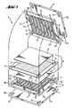
- a single fuel cell 1 (see Figure 1) consists of two electrodes, anode 2 and cathode 3, which are protected by an electrolyte layer, e.g. a proton-conducting polymer membrane 4 are spatially separated from each other.
- Membrane 4 together form a membrane-electrode assembly (MEA) 5.
- MEA membrane-electrode assembly
- the electrochemical oxidation of a fuel e.g. Hydrogen or methanol.
- the released electrons flow through an external circuit to the cathode.
- an oxidizing agent e.g. Oxygen
- the interfaces between electrode and electrolyte are occupied by catalysts 6, which cause an acceleration of the electrode reactions.
- a plurality of fuel cells are often combined in a cell stack to achieve the required performance.
- the cells stacked on top of one another or behind one another are held together by longitudinal screw connections (not shown in FIG. 1). Before the first and after the last cell, the "stack" is closed by end plates.
- the cells are electrically in series within a "stack", but connected in parallel with respect to the media guide.
- the electrical contact between the successive cells are made by bipolar plates (BPP) 7.
- BPP bipolar plates
- distribution structures with flow paths 17, eg channels, are embedded in the surfaces of the BPP 7.
- the media distribution structure 12 on the anode side of the BPP 7 serves to distribute the fuel over the surface of the anode 2, the media distribution structure 13 on the cathode side to distribute the oxidant over the surface of the cathode 3.
- the media distribution structures 12, 13 are via inlets 15 and outlets 14 to the corresponding media supply paths 8, 10 and Ruleabbow 9, 11 connected.
- Protruding elements 16, e.g. Webs on the BPP surface establish electronic contact with the adjacent electrode.
- the structure of the plate surface thus has two tasks to fulfill: distribution of the reaction medium and electrical contacting of the adjacent electrode, and is therefore also referred to below as the contact and distribution structure.
- each BPP 7 is sealed against the oxidant supply path 10 and the oxidant discharge path 11 and the cathode side K against the fuel supply path 8 and the fuel discharge path 9.
- the BPP 7 may be constructed as a combination of an anode-side plate 7a and a cathode-side plate 7b.
- the adjoining surfaces of the two partial bipolar plates 7a and 7b may enclose a coolant distribution structure (not shown in FIG. 1). This version is referred to below as a cold plate composite.
- Removal of the coolant are further provide the "stack" traversing transport routes, and the transport routes of the coolant and the reaction media must also be sealed against each other.
- the complex function of the contact plates results in high demands on the material used: electrical conductivity, impermeability to the reaction media (function as a separator), thermal and mechanical stability under the operating conditions of the fuel cell (for polymer membrane fuel cells up to 120 ° C), chemical resistance to the reaction media and corrosion resistance.
- the material for the production of complicated flow structures must be easy to shape and process. Suitable materials include graphite-plastic composites, ie plastics filled to a very high degree with conductive graphite or carbon particles. Conventionally, these composites are included Pressed increased pressure and elevated temperature to plate blanks and provided in a second operation, for example by CNC milling with the media distribution structure. By means of a correspondingly shaped pressing tool structured plates can be produced in one operation. However, in these methods the cycle times are relatively long.
- Process optimization includes, inter alia, improving the mixing of the components (WO-A 0044005), increasing the injection pressure to 13 * 10 6 to 500 * 10 6 N / m 2 (US-A 6180275), increasing the injection speed to at least 500 mm / s and increasing the nozzle temperature by 40 to 80 K above the melting temperature of the material. (WO-A 0030203).
- a conductive plate made of corrosion resistant Metal or carbon with a plastic frame containing openings for media supply and stipulateabbowwege encapsulated (WO-A 9750139).
- a conductive plate overmolded with a plastic frame may be made by hot pressing or injection-compression molding a preform (a blank) of a graphite-plastic composite (WO-A-0180339).
- WO 00/410260 electrically conductive Kopntaktplatten for fuel cells which have longitudinal channels with intervening webs, wherein the edges of the webs and the transitions of the channel walls may be formed rounded to the channel bottom, or the channel walls are chamfered.
- Such plates may be formed, for example, by pressing or injection molding a composite of a conductive powder, e.g. Graphite, and a polymer binder, e.g. an injection-moldable polyvinylidene fluoride, wherein the graphite content should be 70 to 90%.
- the object of the present invention is to provide a method which makes it possible to produce contact plates (bipolar plates) with a conductivity perpendicular to the plane of at least 20 S / cm for electrochemical cells by injection molding of a composite material, the graphite as a conductive component and a light processable conventional thermoplastic contains as a binder.
- This is intended to overcome the disadvantages of thermoset cycle times, which are increased by the curing time required, as well as the difficult processability of fluorinated thermoplastics and the high cost of specialty materials such as LCP.
- a further object of the invention is to specify a method which makes it possible to produce a contact plate for electrochemical cells by means of injection molding technology, wherein the contact plate has a conductive region with an electrical conductivity of at least 20 S / cm perpendicular to the plate plane, the graphite as a conductive component and a readily processable conventional thermoplastic binder and comprises a non-conductive edge region adjoining the conductive region.
- the solution to this problem consists in the method according to claim 31.
- a structure which defines the flow paths 17 required for the uniform distribution of the reaction media.
- This structure comprises, on the one hand, the recessed areas through which the reaction media flow (hereinafter referred to as channels 17, without restricting it to a specific geometry) and, on the other hand, the electrode contacting contact structure elements 16 (eg, the channels delimiting the channels) which project from the recesses of the media distribution structure. or stand-alone projections with, for example, quadrangular base area, hereinafter referred to as projections independently of their specific geometry).
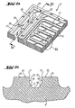
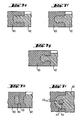
- a section of a bipolar plate 7 with a tortuous flow channel 17 is shown in FIG. 2a.
- the projections 16 on the surface of the bipolar plate 7 correspond to the cavity in the injection mold, which must be completely filled.
- the filling of these recesses is guaranteed all the more reliably, the better their shape is adapted to the flow behavior of the material (flow engineering design). Therefore, it is advantageous to make all projections rounded, as shown in Figures 2a and 2b. This is true for both the junctions 18 from the bottom 19 to the wall surfaces 20 of the channels 17 and the transitions 21 from the channel walls 20 to the surfaces (the contact surfaces) 22 of the projections 16.
- a rounding radius of 0.1 to 0.5 mm has proved to be advantageous. These roundings also facilitate demolding (removal of the plate from the tool).
- An alternative to this approach is to lay the projections from the outset at least by the radius of the rounding higher than needed in the "stack", and then remove the additional material from the surface of the projection again, so that a projection without fillets at the transitions of the channel walls 20 is obtained to the surface 22.
- radii of curvature between one-tenth and one-half the width of the channel are suitable.
- Round channel cross sections are also fluidically advantageous because they counteract the formation of dead volume. This aerodynamic advantage may at least partially compensate for the disadvantage that the proportion of the contact surfaces 16, which are not available for the media distribution, may have to be increased at the media distribution and contact structure in order to ensure the electrical contact.
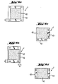
- the apertures for the media supply paths 8,10 and media discharge paths 9,11 and the Leksverschraubungen are preferably arranged outside the conductive region, which is provided for the media distribution and the electrical contacting of the electrode.
- the apertures are located on the sides or corners of the plates and are enclosed by only a narrow rim to minimize material usage and inactive panel area for contacting and supplying the electrodes. This area of the plate is a mechanical weak point, so it is advantageous to provide a support bar 26 for stabilizing the edge web, which bridges the breakthrough.
- the support web 26 is preferably thinner than the plate itself. For reasons of stability, a minimum thickness of 0.8 mm is necessary for the support bar. After passing through the support bar 26, the divided by the support bar currents can reunite. The disturbance of the flow path through the support bar must be kept low and the formation of a dead volume behind the support bar can be prevented. This will be streamlined by the rounded, streamlined cross section of the support web 26. ( Figure 2d)
- the areas of the apertures 24 can be completely filled in the tool, and the desired openings 24 are then punched out.
- the punching of the apertures within the tool by Kernzugtechnik or Injection-compression molding, or in an integrated process step following demoulding.
- a groove 27 may be provided for receiving a seal.
- the plate can be provided on both sides with a Jurverteil- and contact structure with the features described above.
- the channel depth is preferably chosen so that the residual wall thickness at the thinnest points of the plate does not fall below 0.8 mm.
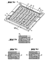
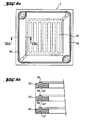
- FIG. 3a The design of the sprue also has a strong influence on the filling of the tool.
- FIG. 3a the representation of the media distribution structure is omitted in FIG. 3a.
- the illustrated or not illustrated structures are not intended to be specific to a particular structure, because the sprue-related aspects of the method described below are independent of the particular flow path structure and equally apply to bipolar plates, end plates, and cold plates. So generally contact plates too.
- the thickness of the film cut 29 can be varied between a minimum determined by the particle size of the conductive filler (for typical graphite particles 0.3 mm) and the thickness of the contact plate 7.
- the width of the gate can in the range from a minimum of 5 mm to the width of the plate 7 can be selected.
- a hot runner system with one or more hot runner nozzles. Because of the lower flowability of the composite material compared to unfilled plastics, the gate diameter of the hot runner nozzle must be greater than usual in the injection molding of unfilled plastics, preferably at least 5 mm.
- sprue channels with a needle valve can be used.
- the needle closures are hydraulically controlled.
- the gate may also be cast directly on the plate surface if its structure contains areas where there is sufficient space for positioning such gate nozzle. Avoiding raised sprue marks in the form of protruding burrs. To accomplish this, the mouth of the runner is positioned in the tool to be lower than the surrounding plate surface of the tool-to-mold plate (recess 30 in Figs. 3a and 3c).
- the small thickness of the contact plate 7 (typically 1 to 3 mm) can cause EntungsungsschwierIERen.
- Entformungsschrägen be provided both on the end faces 33 of the contact plate and on the wall surfaces 34 of the apertures 24, the lateral wall surfaces 22 of the channels 17th and optionally at paragraphs 35 on the disk surface.
- the circumscribed by the paragraph 35 recess 36 in the disk surface is used for embedding the electrode 2 and 3 respectively.
- the structure of the contact plate 7 must not be affected by the ejector during demolding.
- Conventional ejector pins 37 leave markings (impressions) on the surface of the workpiece.
- Such ejectors 37 are therefore preferably positioned so that they encounter the bottom of Dichtungsnuten 27 during the demolding process. (FIGS. 5a and 5b)
- the ejector markings remaining there do not impair the function of the contact plate 7 since, after filling the seal groove with a seal, they are completely covered and sealed by the seal which adapts to the shape of the groove.
- ejector 38 (FIGS. 5a and 5b). These ejectors have recesses and cover the contact plate 7 at the edges, so that it lies exactly in the recesses of the ejector 38. The recesses are shaped so that they project beyond the parting plane of the two tool halves on the end face of the workpiece. In this ejector design accounts for the forced recoilers.
- a further embodiment possibility is that connect at individual edges of the conductive region 42 of the contact plate 7 regions 43 of a non-conductive material to accommodate functional elements that do not have to be electrically conductive. Some variants are shown in FIGS. 6c and 6d.
- this embodiment consists in that at least one edge of the plate, a region 43 of non-conductive material with arbitrary width b connects, but the conductive region is not completely enclosed by non-conductive edge portions 43 .
- the complete contact plate with the conductive areas 42 of the highly filled material and the non-conductive regions 43 made of graphite-free material by injection molding in a tool (two-component method).
- Another advantage of the combination of the two materials is the effect that the plastic component accumulates on the surface of the workpiece in the injection molding of graphite-plastic composite materials due to their greater flowability.
- This plastic-enriched layer improves the adhesion of the plastic sealing frame to the outer edges of the conductive plate.
- the frame may be configured to simultaneously perform a sealing function. It should be noted that the membrane 4 should not reach into the range of this sealing function, because the membrane materials according to the current state of the art are sensitive to mechanical stresses, such as occur during compression of the sealing frames of the successive cells.
- frames 43 made of an elastomer are particularly advantageous for the prevention of leakage between the successive cells 1.
- This sealing frame 43 is designed so that it protrudes in the compressed state with the embedded in the recess 36 electrode 2 or 3 flush surface of the plate 7 by half the thickness of the membrane 6 coated with the catalyst 6.
- the lying between the plates MEA 5 is tightly enclosed.
- the sealing frame 43 according to the invention in the compressed state projects beyond the contact structure elements 16 by half the thickness of the entire membrane-electrode unit 5 in order to cooperate with the likewise formed frames of the following contact plate 7, the MEA 5 tightly enclose.
- the thicknesses of the currently used membranes 5 are 100 to 200 microns and the thicknesses of conventional electrodes 2, 3 200 to 300 microns.
- a frame made of any plastic that is stable under the conditions of fuel cell operation can be designed to perform a sealing function in cooperation with the frames of the adjacent cells (FIGS. 8a and 8b).
- the frame 43 is provided on a surface with a circumferential ledge (spring) 46 and on the rear surface with a matching groove 47.
- spring When tightening the longitudinal screw connection of the "stack" each spring engages in the groove of the frame of the following plate (tongue and groove connection), so that a tight seal is achieved.
- the cross-sections of the mating projections and grooves are typically trough-shaped.
- a conventional sealing material (not shown), preferably a flat sealing strip, are inserted, which is then pressed together under the action of the ledge 46 on the frame 43 of the adjacent plate and so the gap between the two frames 43rd closes tightly.
- a conventional sealing material preferably a flat sealing strip
- a sealing material may be injection molded onto the surface of the plate or frame.
- sealing grooves 27 are provided in the surface of the plate or the frame.
- FIG. 9 shows a section of a stack of a plurality of fuel cells 1 in cross-section with exemplary embodiments of the seals.
- the bipolar plates between the membrane-electrode assemblies 5 are formed as a composite of two partial plates 7a, 7b. Exemplary of the feed paths crossing the "stack" and
- the fuel supply path 8 is connected via at least one inlet 14 to the flow paths 17 of the media distribution structure on the anode-side sub-plate 7a.
- the seals 48 close off the media distribution structures on the surfaces of the BPP sub-plates 7a, 7b facing the membrane-electrode unit 5, against the supply paths and discharge paths of the respective other media passing through these plates.
- the electrodes 2, 3 are embedded in recesses 36.
- the edge region of the membrane 4 projects beyond the electrodes 2, 3.
- the seals 48 are located between the surface of a contact plate 7 and the adjacent membrane. 4
- seals 48 are very sensitive to mechanical stress, for example by folding.
- the seals 48 are therefore preferably formed flat to such a stress on the membrane to avoid.
- the seal groove 48a is made more ready than the seal 48 to allow for lateral displacement of the seal material upon compression of the seal 48.
- the BPP 7, as shown in FIG. 9, consists of an anode and a cathode plate 7a, and 7b, which surround a coolant distribution structure 49 (cooling plate assembly), seals 50 are also required between these plates in order to separate the coolant distribution channels 49 and the feed and seal off discharge paths of the other media against each other. Since seal 50 does not contact the sensitive membrane but lies between two plates 7a and 7b, it is not necessary to make seal 50 flat.
- the residual wall thickness of the plate 7 in the region of the seal groove 51 is not too low, in particular not thinner than the minimum value of 0.8 mm, it is advantageous if the seal 50 is not in its entire height of only one of the two plates 7a, 7b must be recorded. Therefore, cooperating sealing grooves 51b and 51b, each having a part, preferably half, of the height required to receive the gasket 51 in the compressed state are provided in the contiguous plates.
- sealing groove 51a is completely filled in width with the material of the seal 50, which in turn projects beyond the plate surface.
- the region of the plate on which the seal is intended to rest does not consist of the graphite-plastic composite material, but of a graphite-free plastic which is similar to the sealing material or compatible with the sealing material. Due to the similarity between both plastic materials can be a better composite material can be achieved than between the plastic of the seal and the graphite of the conductive region.
- the region of the contact plate on which the seal is intended to rest for example the frame, consists of graphite-free plastic.
- contact plate without frame or edge regions 43 made of graphite-free plastic molding of the plate made of a graphite-plastic composite material and the application of the seal on the plate according to the invention can be carried out by injection molding in a tool in two-component technology.
- the transitions from the sealing grooves to the plate surface are rounded, as well as the flow channels, to achieve good filling of the injection molding tool with the graphite-plastic composite.
- the plate with the stipulateverteil- and contact structure optionally with a non-conductive region with other functional elements, including the seal by injection molding in a tool (multi-component method).
- a cycle time of 45 to 50 seconds is needed to fabricate a conductive plate having the above fuel cell performance characteristics of a composite polypropylene material and a mass fraction of 86% synthetic graphite having a 140 mm x 140 mm plate area.
- the conductivity across the board level corresponds to the requirements for fuel cell operation with at least 20 S / cm.
- Typical structural dimensions for the flow channels 17 are 0.6 to 0.8 mm (width and depth)
- the few micron thick surface layer in which the plastic component of the composite is enriched by abrasion, for example by sandblasting, can be removed.
Landscapes
- Engineering & Computer Science (AREA)
- Manufacturing & Machinery (AREA)
- Chemical & Material Sciences (AREA)
- General Chemical & Material Sciences (AREA)
- Sustainable Energy (AREA)
- Sustainable Development (AREA)
- Chemical Kinetics & Catalysis (AREA)
- Electrochemistry (AREA)
- Life Sciences & Earth Sciences (AREA)
- Mechanical Engineering (AREA)
- Dispersion Chemistry (AREA)
- Composite Materials (AREA)
- Fuel Cell (AREA)
- Laminated Bodies (AREA)
- Battery Electrode And Active Subsutance (AREA)
- Sealing Battery Cases Or Jackets (AREA)
- Injection Moulding Of Plastics Or The Like (AREA)
- Moulds For Moulding Plastics Or The Like (AREA)
Applications Claiming Priority (2)
| Application Number | Priority Date | Filing Date | Title |
|---|---|---|---|
| DE10216306 | 2002-04-14 | ||
| DE10216306A DE10216306B4 (de) | 2002-04-14 | 2002-04-14 | Verfahren zur Herstellung einer Kontaktplatte für eine elektrochemische Zelle sowie deren Verwendungen |
Publications (3)
| Publication Number | Publication Date |
|---|---|
| EP1367664A2 EP1367664A2 (de) | 2003-12-03 |
| EP1367664A3 EP1367664A3 (de) | 2004-06-09 |
| EP1367664B1 true EP1367664B1 (de) | 2007-02-28 |
Family
ID=28684994
Family Applications (1)
| Application Number | Title | Priority Date | Filing Date |
|---|---|---|---|
| EP03008343A Expired - Lifetime EP1367664B1 (de) | 2002-04-14 | 2003-04-10 | Graphithaltige Bipolarplatte mit Polypropylen als Polymerbinder |
Country Status (8)
| Country | Link |
|---|---|
| US (1) | US20030194597A1 (da) |
| EP (1) | EP1367664B1 (da) |
| JP (1) | JP2004031330A (da) |
| AT (1) | ATE355626T1 (da) |
| DE (2) | DE10216306B4 (da) |
| DK (1) | DK1367664T3 (da) |
| ES (1) | ES2280641T3 (da) |
| PT (1) | PT1367664E (da) |
Cited By (1)
| Publication number | Priority date | Publication date | Assignee | Title |
|---|---|---|---|---|
| EP3444884A1 (de) | 2017-08-17 | 2019-02-20 | FRAUNHOFER-GESELLSCHAFT zur Förderung der angewandten Forschung e.V. | Elektrisch leitfähige kontaktplatte für elektrochemische zellen, elektrochemische zelle mit einer solchen kontaktplatte sowie verfahren zu deren herstellung |
Families Citing this family (41)
| Publication number | Priority date | Publication date | Assignee | Title |
|---|---|---|---|---|
| US20040023090A1 (en) * | 2002-03-30 | 2004-02-05 | Pearson Kenneth E. | Fuel cell system |
| WO2004051777A2 (en) * | 2002-12-04 | 2004-06-17 | Lynntech Power Systems, Ltd. | Electrochemical cell plate with integral seals |
| DE10259386A1 (de) * | 2002-12-19 | 2004-07-01 | GHW Gesellschaft für Hochleistungselektrolyseure zur Wasserstofferzeugung mbH | Druckelektrolyseur und Zellrahmen für einen solchen |
| US7195836B2 (en) * | 2003-03-07 | 2007-03-27 | General Motors Corporation | Polymeric separator plates |
| EP1526594A3 (en) * | 2003-10-24 | 2010-05-12 | Panasonic Corporation | Mold for fuel cell separator, method of producing fuel cell separator, fuel cell separator, apparatus of producing fuel cell separator and fuel cell |
| US20050136317A1 (en) * | 2003-12-19 | 2005-06-23 | 3M Innovative Properties Company | Molded multi-part flow field structure |
| US7651809B2 (en) * | 2003-12-26 | 2010-01-26 | Honda Motor Co., Ltd. | Channel member for providing fuel gas to separators forming a plurality of fuel gas fields on one surface |
| DE102004009869B4 (de) * | 2004-02-26 | 2010-12-30 | Reinz-Dichtungs-Gmbh | Kontaktplatte für Brennstoffzellen, Brennstoffzelle und Brennstoffzellenstapel sowie Verfahren zur Herstellung einer Kontaktplatte |
| DE102004015601B4 (de) * | 2004-03-30 | 2009-01-29 | Wilhelm Karmann Gmbh | Brennstoffzelle |
| JP4515824B2 (ja) * | 2004-05-27 | 2010-08-04 | Ntn株式会社 | 高精度すべり軸受 |
| JP2006032041A (ja) * | 2004-07-14 | 2006-02-02 | Toyota Motor Corp | 燃料電池、その製造方法、及びセパレータ |
| KR100637490B1 (ko) * | 2004-09-17 | 2006-10-20 | 삼성에스디아이 주식회사 | 연료 전지용 스택과 이를 갖는 연료 전지 시스템 |
| EP1653537A1 (de) * | 2004-10-29 | 2006-05-03 | Sgl Carbon Ag | Kühlplattenmodul für einen Brennstoffzellenstack |
| FR2882680B1 (fr) * | 2005-03-03 | 2009-05-15 | Seropa Technology Sa | Procede et dispositif de fabrication d'un objet mince par moulage d'une matiere thermoplastique |
| JP5000853B2 (ja) * | 2005-03-24 | 2012-08-15 | パナソニック株式会社 | 燃料電池用セパレータ材料の製造方法と燃料電池用セパレータ並びに燃料電池 |
| WO2006111990A1 (en) * | 2005-04-21 | 2006-10-26 | Ansaldo Fuel Cells S.P.A. | Fuel cell separator plate |
| FR2887686B1 (fr) * | 2005-06-28 | 2010-08-13 | Peugeot Citroen Automobiles Sa | Joint d'etancheite et cellule de pile a combustible comportant un tel joint appose sur les plaques bipolaires |
| FR2887691B1 (fr) * | 2005-06-28 | 2007-09-14 | Peugeot Citroen Automobiles Sa | Plaque monopolaire d'extremite d'une pile a combustible et pile a combustible comprenant une telle plaque |
| DE102005062643A1 (de) * | 2005-12-23 | 2007-07-05 | Carl Freudenberg Kg | Dichtungsanordnung für flächige Bauteile und Verfahren zu deren Herstellung |
| FR2899386A1 (fr) * | 2006-03-29 | 2007-10-05 | Peugeot Citroen Automobiles Sa | Assemblage elementaire d'une pile a combustible comprenant un composant elastique. |
| DE102006041296A1 (de) * | 2006-09-01 | 2008-03-06 | Behr Gmbh & Co. Kg | Scheibenelement für eine Stromabnehmerplatte oder Bipolarplatte einer Brennstoffzelle |
| KR100884473B1 (ko) * | 2007-03-28 | 2009-02-20 | 삼성에스디아이 주식회사 | 폴리머 전지 팩 |
| TWI416791B (zh) * | 2007-07-04 | 2013-11-21 | Wistron Corp | 燃料電池之連接結構 |
| FR2944915A1 (fr) * | 2009-04-27 | 2010-10-29 | Air Liquide | Plaque de pile a combustible, son procede de fabrication et pile a combustible correspondante. |
| US8911918B2 (en) * | 2010-02-08 | 2014-12-16 | GM Global Technology Operations LLC | Hybrid seal application process |
| FR2958456B1 (fr) * | 2010-03-30 | 2012-05-04 | Air Liquide | Plaque de pile a combustible, cellule et pile correspondantes |
| CN101826621A (zh) * | 2010-03-30 | 2010-09-08 | 上海恒劲动力科技有限公司 | 燃料电池用双极板 |
| KR101934600B1 (ko) * | 2010-06-25 | 2019-01-02 | 디에스엠 아이피 어셋츠 비.브이. | 중합체 부품의 조립물 |
| EP2750855B1 (en) * | 2011-08-30 | 2017-06-14 | Husky Injection Molding Systems Ltd. | A stripper sleeve |
| US9196909B2 (en) * | 2011-11-18 | 2015-11-24 | Bloom Energy Corporation | Fuel cell interconnect heat treatment method |
| EP3514873B1 (en) * | 2013-09-23 | 2021-05-19 | Lockheed Martin Energy, LLC | Bipolar plate design with non-conductive picture frame |
| GB201504498D0 (en) * | 2015-03-17 | 2015-04-29 | Penso Holdings Ltd | Method and apparatus for production of carbon fibre components |
| TWI575805B (zh) * | 2015-10-15 | 2017-03-21 | 行政院原子能委員會核能研究所 | 液流電池之雙極板及其製作方法 |
| WO2018069996A1 (ja) * | 2016-10-12 | 2018-04-19 | 住友電気工業株式会社 | 双極板、セルフレーム、セルスタック、及びレドックスフロー電池 |
| DE102018200818A1 (de) * | 2018-01-18 | 2019-07-18 | Zae Bayern Bay. Zentrum Für Angewandte Energieforschung E.V. | Monopolarplattenbauteil für chemische Reaktoren, insbesondere für Redox-Flow-Batterien, Verfahren zur Herstellung eines Monopolarplattenbauteils und Redox-Flow-Batterie mit einem solchen Monopolarplattenbauteil |
| CN110931820A (zh) * | 2019-12-10 | 2020-03-27 | 张国胜 | 双极板的整体错位组装方法及包含该双极板的燃料电池电堆和发电系统 |
| DE102021204917A1 (de) * | 2021-05-14 | 2022-11-17 | Cellcentric Gmbh & Co. Kg | Strömungsfeld und Separatorplatte |
| WO2023219648A1 (en) | 2022-05-09 | 2023-11-16 | Lockheed Martin Energy, Llc | Flow battery with a dynamic fluidic network |
| DE102022115645A1 (de) | 2022-06-23 | 2023-12-28 | Schaeffler Technologies AG & Co. KG | Redox-Flow-Batterie und Verfahren zur Herstellung einer Redox-Flow-Batterie |
| CN115107220B (zh) * | 2022-07-19 | 2023-07-18 | 东莞市谷麦光学科技有限公司 | 一种双色注塑模具 |
| DE102023105976A1 (de) | 2023-03-10 | 2023-12-28 | Schaeffler Technologies AG & Co. KG | Polymergraphitische Bipolarplatte und Verfahren zur Herstellung einer Bipolarplatte |
Family Cites Families (33)
| Publication number | Priority date | Publication date | Assignee | Title |
|---|---|---|---|---|
| FR81971E (da) * | 1961-05-08 | 1964-03-04 | ||
| US4174020A (en) * | 1975-07-01 | 1979-11-13 | Challis Louis A | Acoustic treatment for fans |
| DE3403603C2 (de) * | 1984-02-02 | 1985-12-05 | Maschinenfabrik Köppern GmbH & Co KG, 4320 Hattingen | Zwangsgesteuerter Nadelverschluß für Spritzdüsen in Spritzgießformen |
| JPH05104592A (ja) * | 1991-10-17 | 1993-04-27 | Olympus Optical Co Ltd | 微細パターンを有する製品の成形用金型 |
| US5429492A (en) * | 1992-12-23 | 1995-07-04 | Taniyama; Yoshihiko | Plastic molding apparatus |
| DE4309976A1 (de) * | 1993-03-26 | 1994-09-29 | Daimler Benz Ag | Elektrochemische Mehrzellenbatterie |
| IT1270878B (it) * | 1993-04-30 | 1997-05-13 | Permelec Spa Nora | Migliorata cella elettrochimica utilizzante membrane a scambio ionico e piatti bipolari metallici |
| US5514487A (en) * | 1994-12-27 | 1996-05-07 | Ballard Power Systems Inc. | Edge manifold assembly for an electrochemical fuel cell stack |
| US5879826A (en) * | 1995-07-05 | 1999-03-09 | Humboldt State University Foundation | Proton exchange membrane fuel cell |
| GB9526577D0 (en) * | 1995-12-28 | 1996-02-28 | Nat Power Plc | Method for the fabrication of electrochemical cells |
| CA2259196A1 (en) * | 1996-06-25 | 1997-12-31 | Yuko Fukuoka | Polymer electrolyte membrane fuel cell with bipolar plate having integrally molded conductive insert |
| US6096450A (en) * | 1998-02-11 | 2000-08-01 | Plug Power Inc. | Fuel cell assembly fluid flow plate having conductive fibers and rigidizing material therein |
| WO1999049530A1 (fr) * | 1998-03-20 | 1999-09-30 | Osaka Gas Company Limited | Separateur pour element a combustible et son procede de production |
| JPH11291296A (ja) * | 1998-04-07 | 1999-10-26 | Nissan Motor Co Ltd | 射出成形型 |
| FR2786027B1 (fr) * | 1998-11-12 | 2006-04-28 | Commissariat Energie Atomique | Plaques bipolaires pour pile a combustible et pile a combustible comprenant ces plaques |
| US6180275B1 (en) * | 1998-11-18 | 2001-01-30 | Energy Partners, L.C. | Fuel cell collector plate and method of fabrication |
| CA2357928A1 (en) * | 1998-12-30 | 2000-07-13 | Ballard Power Systems Inc. | Fuel cell fluid flow field plate and methods of making fuel cell flow field plates |
| US6379795B1 (en) * | 1999-01-19 | 2002-04-30 | E. I. Du Pont De Nemours And Company | Injection moldable conductive aromatic thermoplastic liquid crystalline polymeric compositions |
| DE19910487C1 (de) * | 1999-03-10 | 2000-06-15 | Freudenberg Carl Fa | Verfahren und Werkzeug zur Herstellung von Bipolarplatten |
| US6436315B2 (en) * | 1999-03-19 | 2002-08-20 | Quantum Composites Inc. | Highly conductive molding compounds for use as fuel cell plates and the resulting products |
| US6365069B2 (en) * | 1999-03-19 | 2002-04-02 | Quantum Composites Inc. | Process of injection molding highly conductive molding compounds and an apparatus for this process |
| WO2000062312A1 (fr) * | 1999-04-12 | 2000-10-19 | Toyota Jidosha Kabushiki Kaisha | Produit a parties conductrices en resine hautement conductrice, et procede de fabrication |
| CA2311196C (en) * | 1999-06-14 | 2005-08-16 | Kawasaki Steel Corporation | A fuel cell separator, a fuel cell using the fuel cell separator, and a method for making the fuel cell separator |
| US6319625B1 (en) * | 1999-10-29 | 2001-11-20 | George J. Gemberling | Graphite plate assembly and method of manufacture |
| US6255012B1 (en) * | 1999-11-19 | 2001-07-03 | The Regents Of The University Of California | Pleated metal bipolar assembly |
| CN1229886C (zh) * | 1999-12-06 | 2005-11-30 | 日立化成工业株式会社 | 燃料电池、燃料电池隔板及其制造方法 |
| US6780533B2 (en) * | 1999-12-17 | 2004-08-24 | Utc Fuel Cells, Llc | Fuel cell having interdigitated flow channels and water transport plates |
| NL1014405C1 (nl) * | 2000-02-17 | 2001-08-20 | Nedstack Holding B V | Methode voor het vervaardigen Polymeer Elektrolyt Brandstofcellen. |
| EP1160900A3 (en) * | 2000-05-26 | 2007-12-12 | Kabushiki Kaisha Riken | Embossed current collector separator for electrochemical fuel cell |
| FR2810795B1 (fr) * | 2000-06-27 | 2002-10-04 | Technicatome | Plaque bipolaire a deux plaques metalliques pour pile a combustible et son procede de fabrication |
| FR2812120B1 (fr) * | 2000-07-24 | 2006-11-03 | Commissariat Energie Atomique | Materiau composite conducteur et electrode pour pile a combustible utilisant ce materiau |
| US6777127B2 (en) * | 2001-06-22 | 2004-08-17 | Ballard Power Systems Inc. | Systems, apparatus and methods for bonding and/or sealing electrochemical cell elements and assemblies |
| DE10159116A1 (de) * | 2001-12-01 | 2003-06-12 | Krauss Maffei Kunststofftech | Verfahren zur Herstellung von Elektrodenplatten durch Spritzgießen aus mit Graphit od. dgl. beladenem Kunststoff |
-
2002
- 2002-04-14 DE DE10216306A patent/DE10216306B4/de not_active Expired - Fee Related
-
2003
- 2003-04-10 AT AT03008343T patent/ATE355626T1/de active
- 2003-04-10 EP EP03008343A patent/EP1367664B1/de not_active Expired - Lifetime
- 2003-04-10 DK DK03008343T patent/DK1367664T3/da active
- 2003-04-10 PT PT03008343T patent/PT1367664E/pt unknown
- 2003-04-10 ES ES03008343T patent/ES2280641T3/es not_active Expired - Lifetime
- 2003-04-10 DE DE50306625T patent/DE50306625D1/de not_active Expired - Lifetime
- 2003-04-14 JP JP2003109022A patent/JP2004031330A/ja active Pending
- 2003-04-14 US US10/413,038 patent/US20030194597A1/en not_active Abandoned
Cited By (2)
| Publication number | Priority date | Publication date | Assignee | Title |
|---|---|---|---|---|
| EP3444884A1 (de) | 2017-08-17 | 2019-02-20 | FRAUNHOFER-GESELLSCHAFT zur Förderung der angewandten Forschung e.V. | Elektrisch leitfähige kontaktplatte für elektrochemische zellen, elektrochemische zelle mit einer solchen kontaktplatte sowie verfahren zu deren herstellung |
| DE102017007718A1 (de) | 2017-08-17 | 2019-02-21 | Fraunhofer-Gesellschaft zur Förderung der angewandten Forschung e.V. | Elektrisch leitfähige Kontaktplatte für elektrochemische Zellen, elektrochemische Zelle mit einer solchen Kontaktplatte sowie Verfahren zu deren Herstellung |
Also Published As
| Publication number | Publication date |
|---|---|
| DE50306625D1 (de) | 2007-04-12 |
| DE10216306A1 (de) | 2003-11-20 |
| ES2280641T3 (es) | 2007-09-16 |
| EP1367664A3 (de) | 2004-06-09 |
| PT1367664E (pt) | 2007-04-30 |
| DE10216306B4 (de) | 2008-06-12 |
| US20030194597A1 (en) | 2003-10-16 |
| JP2004031330A (ja) | 2004-01-29 |
| ATE355626T1 (de) | 2006-03-15 |
| DK1367664T3 (da) | 2007-06-18 |
| EP1367664A2 (de) | 2003-12-03 |
Similar Documents
| Publication | Publication Date | Title |
|---|---|---|
| EP1367664B1 (de) | Graphithaltige Bipolarplatte mit Polypropylen als Polymerbinder | |
| DE112007000860B4 (de) | Film-Elektroden-Anordnung für eine Brennstoffzelle, Polymerelektrolyt-Brennstoffzelle und Verfahren zum Herstellen einer Film-Elektroden-Anordnung | |
| DE602004001520T2 (de) | Membranelektrodenbaugruppe mit integrierter dichtung | |
| EP3378117B1 (de) | Bipolarplatte mit asymmetrischen dichtungsabschnitten, sowie brennstoffzellenstapel mit einer solchen | |
| DE102012214268A1 (de) | Formungs- und Füll-Unterdichtung | |
| DE112008000004B4 (de) | Brennstoffzellenmodul, Brennstoffzelle und Verfahren zum Herstellen eines Brennstoffzellenmoduls | |
| DE112005000945T5 (de) | Separator für eine Brennstoffbatterie, Verfahren zum Verbinden des Separators, sowie Brennstoffbatterie | |
| DE112005000938T5 (de) | Brennstoffzellenmodul | |
| DE112008000567T5 (de) | Polymerelektrolytbrennstoffzelle | |
| EP3659198B1 (de) | Elektrochemisch aktive einheit für eine elektrochemische vorrichtung | |
| DE102017101958A1 (de) | Brennstoffzelle und Verfahren zur Herstellung einer Brennstoffzelle | |
| DE102012205546A1 (de) | Brennstoffzelle und vorrichtung zur herstellung einer brennstoffzelle | |
| DE10203612C1 (de) | Brennstoffzellenpaket sowie dafür geeignete bipolare Platte | |
| DE102014015219A1 (de) | Ausrichtungsbestandteil und Verfahren zum Ausrichten in Brennstoffzellenstapeln | |
| EP1653538A1 (de) | Kühlplattenmodul mit integralem Dichtungselement für einen Brennstoffzellenstack | |
| DE60305267T2 (de) | Separatorplatte für Polymerelektrolytbrennstoffzelle und diese verwendende Polymerelektrolytbrennstoffzelle | |
| DE102010001638A1 (de) | Brennstoffzelle und Verfahren zu deren Herstellung | |
| DE19631329C2 (de) | Dichtung für eine Batterie und ein Verfahren zur Herstellung einer derartigen Dichtung | |
| DE102004057447B4 (de) | Versorgungsplatte sowie deren Verwendung | |
| EP2071653B1 (de) | Bipolarplatte beinhaltend Dichtungselement mit Positionierhilfe für MEA in einem Brennstoffzellenstapel | |
| WO2021122169A1 (de) | Verfahren zum herstellen einer dichtung für eine elektrochemische einheit einer elektrochemischen vorrichtung und baugruppe für eine elektrochemische vorrichtung | |
| DE102007061127B4 (de) | Unipolarplatte und Verfahren zum Formen einer Komposit-Unipolarplatte für einen Brennstoffzellenstapel | |
| DE102015015392A1 (de) | Bipolarplatten-Anordnung, Brennstoffzellensystem und Fahrzeug | |
| WO2014072150A1 (de) | Bipolarplatte für einen elektrolyseur, elektrolyseur und verfahren zur herstellung einer bipolarplatte | |
| WO2017211423A1 (de) | Elektrodenplatte und verfahren zur herstellung |
Legal Events
| Date | Code | Title | Description |
|---|---|---|---|
| PUAI | Public reference made under article 153(3) epc to a published international application that has entered the european phase |
Free format text: ORIGINAL CODE: 0009012 |
|
| AK | Designated contracting states |
Kind code of ref document: A2 Designated state(s): AT BE BG CH CY CZ DE DK EE ES FI FR GB GR HU IE IT LI LU MC NL PT RO SE SI SK TR |
|
| AX | Request for extension of the european patent |
Extension state: AL LT LV MK |
|
| PUAL | Search report despatched |
Free format text: ORIGINAL CODE: 0009013 |
|
| AK | Designated contracting states |
Kind code of ref document: A3 Designated state(s): AT BE BG CH CY CZ DE DK EE ES FI FR GB GR HU IE IT LI LU MC NL PT RO SE SI SK TR |
|
| AX | Request for extension of the european patent |
Extension state: AL LT LV MK |
|
| RIC1 | Information provided on ipc code assigned before grant |
Ipc: 7H 01M 8/24 B Ipc: 7B 29C 45/28 B Ipc: 7B 29C 45/40 B Ipc: 7H 01M 8/02 A |
|
| 17P | Request for examination filed |
Effective date: 20041209 |
|
| 17Q | First examination report despatched |
Effective date: 20050118 |
|
| AKX | Designation fees paid |
Designated state(s): AT BE BG CH CY CZ DE DK EE ES FI FR GB GR HU IE IT LI LU MC NL PT RO SE SI SK TR |
|
| RIC1 | Information provided on ipc code assigned before grant |
Ipc: H01M 8/02 20060101AFI20060630BHEP |
|
| RTI1 | Title (correction) |
Free format text: BIPOLAR PLATE COMPRISING POLYPROPYLENE AS POLYMER BINDER |
|
| GRAP | Despatch of communication of intention to grant a patent |
Free format text: ORIGINAL CODE: EPIDOSNIGR1 |
|
| GRAS | Grant fee paid |
Free format text: ORIGINAL CODE: EPIDOSNIGR3 |
|
| GRAA | (expected) grant |
Free format text: ORIGINAL CODE: 0009210 |
|
| AK | Designated contracting states |
Kind code of ref document: B1 Designated state(s): AT BE BG CH CY CZ DE DK EE ES FI FR GB GR HU IE IT LI LU MC NL PT RO SE SI SK TR |
|
| PG25 | Lapsed in a contracting state [announced via postgrant information from national office to epo] |
Ref country code: SI Free format text: LAPSE BECAUSE OF FAILURE TO SUBMIT A TRANSLATION OF THE DESCRIPTION OR TO PAY THE FEE WITHIN THE PRESCRIBED TIME-LIMIT Effective date: 20070228 |
|
| REG | Reference to a national code |
Ref country code: GB Ref legal event code: FG4D Free format text: NOT ENGLISH |
|
| REG | Reference to a national code |
Ref country code: CH Ref legal event code: EP |
|
| REF | Corresponds to: |
Ref document number: 50306625 Country of ref document: DE Date of ref document: 20070412 Kind code of ref document: P |
|
| REG | Reference to a national code |
Ref country code: CH Ref legal event code: NV Representative=s name: KELLER & PARTNER PATENTANWAELTE AG WINTERTHUR |
|
| REG | Reference to a national code |
Ref country code: IE Ref legal event code: FG4D Free format text: LANGUAGE OF EP DOCUMENT: GERMAN |
|
| REG | Reference to a national code |
Ref country code: PT Ref legal event code: SC4A Free format text: AVAILABILITY OF NATIONAL TRANSLATION Effective date: 20070402 |
|
| PG25 | Lapsed in a contracting state [announced via postgrant information from national office to epo] |
Ref country code: BG Free format text: LAPSE BECAUSE OF EXPIRATION OF PROTECTION Effective date: 20070529 |
|
| GBT | Gb: translation of ep patent filed (gb section 77(6)(a)/1977) |
Effective date: 20070509 |
|
| PG25 | Lapsed in a contracting state [announced via postgrant information from national office to epo] |
Ref country code: SE Free format text: LAPSE BECAUSE OF FAILURE TO SUBMIT A TRANSLATION OF THE DESCRIPTION OR TO PAY THE FEE WITHIN THE PRESCRIBED TIME-LIMIT Effective date: 20070531 |
|
| REG | Reference to a national code |
Ref country code: DK Ref legal event code: T3 |
|
| ET | Fr: translation filed | ||
| REG | Reference to a national code |
Ref country code: ES Ref legal event code: FG2A Ref document number: 2280641 Country of ref document: ES Kind code of ref document: T3 |
|
| PG25 | Lapsed in a contracting state [announced via postgrant information from national office to epo] |
Ref country code: SK Free format text: LAPSE BECAUSE OF FAILURE TO SUBMIT A TRANSLATION OF THE DESCRIPTION OR TO PAY THE FEE WITHIN THE PRESCRIBED TIME-LIMIT Effective date: 20070228 |
|
| REG | Reference to a national code |
Ref country code: IE Ref legal event code: FD4D |
|
| BERE | Be: lapsed |
Owner name: SGL CARBON A.G. Effective date: 20070430 |
|
| PG25 | Lapsed in a contracting state [announced via postgrant information from national office to epo] |
Ref country code: CZ Free format text: LAPSE BECAUSE OF FAILURE TO SUBMIT A TRANSLATION OF THE DESCRIPTION OR TO PAY THE FEE WITHIN THE PRESCRIBED TIME-LIMIT Effective date: 20070228 Ref country code: RO Free format text: LAPSE BECAUSE OF FAILURE TO SUBMIT A TRANSLATION OF THE DESCRIPTION OR TO PAY THE FEE WITHIN THE PRESCRIBED TIME-LIMIT Effective date: 20070228 |
|
| PLBE | No opposition filed within time limit |
Free format text: ORIGINAL CODE: 0009261 |
|
| STAA | Information on the status of an ep patent application or granted ep patent |
Free format text: STATUS: NO OPPOSITION FILED WITHIN TIME LIMIT |
|
| PG25 | Lapsed in a contracting state [announced via postgrant information from national office to epo] |
Ref country code: IE Free format text: LAPSE BECAUSE OF FAILURE TO SUBMIT A TRANSLATION OF THE DESCRIPTION OR TO PAY THE FEE WITHIN THE PRESCRIBED TIME-LIMIT Effective date: 20070228 |
|
| 26N | No opposition filed |
Effective date: 20071129 |
|
| PG25 | Lapsed in a contracting state [announced via postgrant information from national office to epo] |
Ref country code: BE Free format text: LAPSE BECAUSE OF NON-PAYMENT OF DUE FEES Effective date: 20070430 |
|
| PG25 | Lapsed in a contracting state [announced via postgrant information from national office to epo] |
Ref country code: GR Free format text: LAPSE BECAUSE OF FAILURE TO SUBMIT A TRANSLATION OF THE DESCRIPTION OR TO PAY THE FEE WITHIN THE PRESCRIBED TIME-LIMIT Effective date: 20070529 |
|
| PG25 | Lapsed in a contracting state [announced via postgrant information from national office to epo] |
Ref country code: EE Free format text: LAPSE BECAUSE OF FAILURE TO SUBMIT A TRANSLATION OF THE DESCRIPTION OR TO PAY THE FEE WITHIN THE PRESCRIBED TIME-LIMIT Effective date: 20070228 |
|
| PG25 | Lapsed in a contracting state [announced via postgrant information from national office to epo] |
Ref country code: MC Free format text: LAPSE BECAUSE OF NON-PAYMENT OF DUE FEES Effective date: 20070430 |
|
| PG25 | Lapsed in a contracting state [announced via postgrant information from national office to epo] |
Ref country code: CY Free format text: LAPSE BECAUSE OF FAILURE TO SUBMIT A TRANSLATION OF THE DESCRIPTION OR TO PAY THE FEE WITHIN THE PRESCRIBED TIME-LIMIT Effective date: 20070228 |
|
| PG25 | Lapsed in a contracting state [announced via postgrant information from national office to epo] |
Ref country code: LU Free format text: LAPSE BECAUSE OF NON-PAYMENT OF DUE FEES Effective date: 20070410 |
|
| PG25 | Lapsed in a contracting state [announced via postgrant information from national office to epo] |
Ref country code: HU Free format text: LAPSE BECAUSE OF FAILURE TO SUBMIT A TRANSLATION OF THE DESCRIPTION OR TO PAY THE FEE WITHIN THE PRESCRIBED TIME-LIMIT Effective date: 20070901 Ref country code: TR Free format text: LAPSE BECAUSE OF FAILURE TO SUBMIT A TRANSLATION OF THE DESCRIPTION OR TO PAY THE FEE WITHIN THE PRESCRIBED TIME-LIMIT Effective date: 20070228 |
|
| PGFP | Annual fee paid to national office [announced via postgrant information from national office to epo] |
Ref country code: CH Payment date: 20120420 Year of fee payment: 10 Ref country code: NL Payment date: 20120425 Year of fee payment: 10 Ref country code: DK Payment date: 20120418 Year of fee payment: 10 |
|
| PGFP | Annual fee paid to national office [announced via postgrant information from national office to epo] |
Ref country code: FR Payment date: 20120507 Year of fee payment: 10 Ref country code: FI Payment date: 20120411 Year of fee payment: 10 Ref country code: GB Payment date: 20120419 Year of fee payment: 10 |
|
| PGFP | Annual fee paid to national office [announced via postgrant information from national office to epo] |
Ref country code: IT Payment date: 20120426 Year of fee payment: 10 |
|
| PGFP | Annual fee paid to national office [announced via postgrant information from national office to epo] |
Ref country code: ES Payment date: 20120424 Year of fee payment: 10 |
|
| PGFP | Annual fee paid to national office [announced via postgrant information from national office to epo] |
Ref country code: PT Payment date: 20120404 Year of fee payment: 10 |
|
| PGFP | Annual fee paid to national office [announced via postgrant information from national office to epo] |
Ref country code: AT Payment date: 20120411 Year of fee payment: 10 |
|
| PGFP | Annual fee paid to national office [announced via postgrant information from national office to epo] |
Ref country code: DE Payment date: 20130430 Year of fee payment: 11 |
|
| REG | Reference to a national code |
Ref country code: PT Ref legal event code: MM4A Free format text: LAPSE DUE TO NON-PAYMENT OF FEES Effective date: 20131010 |
|
| REG | Reference to a national code |
Ref country code: NL Ref legal event code: V1 Effective date: 20131101 |
|
| REG | Reference to a national code |
Ref country code: CH Ref legal event code: PL |
|
| REG | Reference to a national code |
Ref country code: DK Ref legal event code: EBP Effective date: 20130430 |
|
| REG | Reference to a national code |
Ref country code: AT Ref legal event code: MM01 Ref document number: 355626 Country of ref document: AT Kind code of ref document: T Effective date: 20130430 |
|
| GBPC | Gb: european patent ceased through non-payment of renewal fee |
Effective date: 20130410 |
|
| PG25 | Lapsed in a contracting state [announced via postgrant information from national office to epo] |
Ref country code: LI Free format text: LAPSE BECAUSE OF NON-PAYMENT OF DUE FEES Effective date: 20130430 Ref country code: AT Free format text: LAPSE BECAUSE OF NON-PAYMENT OF DUE FEES Effective date: 20130430 Ref country code: CH Free format text: LAPSE BECAUSE OF NON-PAYMENT OF DUE FEES Effective date: 20130430 Ref country code: PT Free format text: LAPSE BECAUSE OF NON-PAYMENT OF DUE FEES Effective date: 20131010 Ref country code: GB Free format text: LAPSE BECAUSE OF NON-PAYMENT OF DUE FEES Effective date: 20130410 |
|
| REG | Reference to a national code |
Ref country code: FR Ref legal event code: ST Effective date: 20131231 |
|
| PG25 | Lapsed in a contracting state [announced via postgrant information from national office to epo] |
Ref country code: IT Free format text: LAPSE BECAUSE OF NON-PAYMENT OF DUE FEES Effective date: 20130410 Ref country code: FR Free format text: LAPSE BECAUSE OF NON-PAYMENT OF DUE FEES Effective date: 20130430 Ref country code: FI Free format text: LAPSE BECAUSE OF NON-PAYMENT OF DUE FEES Effective date: 20130410 Ref country code: NL Free format text: LAPSE BECAUSE OF NON-PAYMENT OF DUE FEES Effective date: 20131101 |
|
| PG25 | Lapsed in a contracting state [announced via postgrant information from national office to epo] |
Ref country code: DK Free format text: LAPSE BECAUSE OF NON-PAYMENT OF DUE FEES Effective date: 20130430 |
|
| REG | Reference to a national code |
Ref country code: ES Ref legal event code: FD2A Effective date: 20140606 |
|
| PG25 | Lapsed in a contracting state [announced via postgrant information from national office to epo] |
Ref country code: ES Free format text: LAPSE BECAUSE OF NON-PAYMENT OF DUE FEES Effective date: 20130411 |
|
| REG | Reference to a national code |
Ref country code: DE Ref legal event code: R119 Ref document number: 50306625 Country of ref document: DE |
|
| REG | Reference to a national code |
Ref country code: DE Ref legal event code: R119 Ref document number: 50306625 Country of ref document: DE Effective date: 20141101 |
|
| PG25 | Lapsed in a contracting state [announced via postgrant information from national office to epo] |
Ref country code: DE Free format text: LAPSE BECAUSE OF NON-PAYMENT OF DUE FEES Effective date: 20141101 |