EP1367140A1 - Grain-oriented electrical steel sheet excellent in magnetic properties and method for producing the same - Google Patents
Grain-oriented electrical steel sheet excellent in magnetic properties and method for producing the same Download PDFInfo
- Publication number
- EP1367140A1 EP1367140A1 EP03011166A EP03011166A EP1367140A1 EP 1367140 A1 EP1367140 A1 EP 1367140A1 EP 03011166 A EP03011166 A EP 03011166A EP 03011166 A EP03011166 A EP 03011166A EP 1367140 A1 EP1367140 A1 EP 1367140A1
- Authority
- EP
- European Patent Office
- Prior art keywords
- melted
- steel sheet
- grain
- oriented electrical
- electrical steel
- Prior art date
- Legal status (The legal status is an assumption and is not a legal conclusion. Google has not performed a legal analysis and makes no representation as to the accuracy of the status listed.)
- Granted
Links
Images



Classifications
-
- C—CHEMISTRY; METALLURGY
- C21—METALLURGY OF IRON
- C21D—MODIFYING THE PHYSICAL STRUCTURE OF FERROUS METALS; GENERAL DEVICES FOR HEAT TREATMENT OF FERROUS OR NON-FERROUS METALS OR ALLOYS; MAKING METAL MALLEABLE, e.g. BY DECARBURISATION OR TEMPERING
- C21D8/00—Modifying the physical properties of ferrous metals or ferrous alloys by deformation combined with, or followed by, heat treatment
- C21D8/12—Modifying the physical properties of ferrous metals or ferrous alloys by deformation combined with, or followed by, heat treatment during manufacturing of articles with special electromagnetic properties
-
- C—CHEMISTRY; METALLURGY
- C21—METALLURGY OF IRON
- C21D—MODIFYING THE PHYSICAL STRUCTURE OF FERROUS METALS; GENERAL DEVICES FOR HEAT TREATMENT OF FERROUS OR NON-FERROUS METALS OR ALLOYS; MAKING METAL MALLEABLE, e.g. BY DECARBURISATION OR TEMPERING
- C21D8/00—Modifying the physical properties of ferrous metals or ferrous alloys by deformation combined with, or followed by, heat treatment
- C21D8/12—Modifying the physical properties of ferrous metals or ferrous alloys by deformation combined with, or followed by, heat treatment during manufacturing of articles with special electromagnetic properties
- C21D8/1294—Modifying the physical properties of ferrous metals or ferrous alloys by deformation combined with, or followed by, heat treatment during manufacturing of articles with special electromagnetic properties involving a localised treatment
Definitions
- the present invention relates to a grain-oriented electrical steel sheet which can withstand stress-relieving annealing, being excellent in magnetic properties and being usable for a wound magnetic core, and a method for producing the grain-oriented electrical steel sheet by applying laser processing to either or both of the surfaces of the grain-oriented electrical steel sheet and, by so doing, forming melted and re-solidified layers thereon.
- a method for lowering core loss a method wherein magnetic domains are fractionized by laser irradiation is disclosed in Japanese Examined Patent Publication No. S58-26405.
- the method aims to achieve lower core loss by introducing a stress strain to a grain-oriented electrical steel sheet by the reactive force of thermal shock waves generated by the irradiation of a laser beam and thus by fractionizing magnetic domains.
- a problem of the method is that the strain introduced by laser irradiation disappears during annealing and therefore the effect of fractionizing magnetic domains is lost. Therefore, though the method is applicable to a grain-oriented electrical steel sheet for a laminated core transformer that does not require stress-relieving annealing, it is not applicable to one for a wound core transformer that requires stress-relieving annealing.
- the object of the present invention is, in a grain-oriented electrical steel sheet having melted and re-solidified layers formed by laser processing and excellent magnetic properties even after being subjected to stress-relieving annealing and a production method thereof, to provide a grain-oriented electrical steel sheet that has an increased core loss of the same rank as one produced by the groove forming method, but does not suffer deterioration in magnetic flux density and the lowering of a space factor, and a method for producing the grain-oriented electrical steel sheet.
- the present invention is a grain-oriented electrical steel sheet characterized in that: melted and re-solidified layers are formed on either or both of the surfaces of the grain-oriented electrical steel sheet in the manner of extending in the direction of the width thereof at a constant and cyclic interval of not less than 2 mm to less than 5 mm in the direction of rolling; and the melted and re-solidified layers on each surface of the grain-oriented electrical steel sheet have an aspect ratio, the aspect ratio being the ratio of the depth to the width of a melted and re-solidified layer, of not less than 0.20 and a depth of not less than 15 ⁇ m.
- the widths of melted and re-solidified layers be in the range from not less than 30 ⁇ m to not more than 200 ⁇ m.
- the present invention is a method for producing a grain-oriented electrical steel sheet characterized by irradiating a laser beam on either or both of the surfaces of the grain-oriented electrical steel sheet and thereby forming melted and re-solidified layers thereon.
- the present invention is a method for producing a grain-oriented electrical steel sheet characterized by forming melted and re-solidified layers with a laser beam radiated from a continuous oscillation fiber laser used as a laser device.
- Figure 1 is a graph showing the relation between the aspect ratios at the cross sections of the melted and re-solidified layers formed and the core loss increase rates in the low core loss grain-oriented electrical steel sheets according to the present invention (the melted and re-solidified layers are formed on both the surfaces of each grain-oriented electrical steel sheet at an interval of 3 mm in the rolling direction).
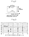
- Figure 2 is a schematic illustrating a sectional photograph of a melted and re-solidified layer formed.
- Figure 3 is a graph showing the relation between the depths of the melted and re-solidified layers formed and the core loss increase rates (the melted and re-solidified layers are formed at an interval of 5 mm in the rolling direction).
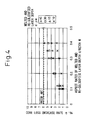
- Figure 4 is a graph showing the relation between the aspect ratios at the cross sections of the melted and re-solidified layers and the core loss increase rates (the melted and re-solidified layers are formed at an interval of 5 mm in the rolling direction).
- Figure 5 is a graph showing the relation between the intervals in the direction of rolling of a steel sheet (the intervals in the L direction), at which intervals the melted and re-solidified layers are formed, and the core loss increase rates.
- Figure 6 is a graph showing the relation between the aspect ratios at the cross sections of the melted and re-solidified layers formed and the core loss increase rates in the low core loss grain-oriented electrical steel sheets according to the present invention (the melted and re-solidified layers are formed on either of the surfaces of each grain-oriented electrical steel sheet at an interval of 3 mm in the rolling direction).
- Figure 7 is a graph showing the relation between the widths of the melted and re-solidified layers formed and the core loss increase rates in the low core loss grain-oriented electrical steel sheets according to the present invention (the melted and re-solidified layers are formed at an interval of 3 mm in the rolling direction).
- Figure 8 is a schematic illustrating the method for producing a low core loss grain-oriented electrical steel sheet with a laser according to the present invention.
- the present inventors in a method for increasing core loss by forming linear melted and re-solidified layers on either or both of the surfaces of a grain-oriented electrical steel sheet in the manner of extending in the direction nearly perpendicular to the rolling direction at a prescribed interval in the rolling direction after finish annealing or insulating film coating was applied, found that an increased core loss exceeding one obtained by the existing melting and re-solidifying method or groove forming method could be obtained even after stress-relieving annealing was applied by restricting the aspect ratio, the interval, the depth and the width at a cross section of each melted and re-solidified layer, the restrictions having never been taken into consideration in existing technologies.
- the embodiments of the present invention are explained hereunder on the basis of the examples.
- FIG. 8 is a schematic explaining the laser beam irradiation method according to the present invention.
- a laser beam LB originating from a laser device 3 was irradiated in a scanning manner on a grain-oriented electrical steel sheet 1 by using a scanning mirror 4 and an f ⁇ lens 5, as shown in the figure.
- Numeral 6 denotes a cylindrical lens and, if necessary, it is used for converting the shape of a condensed laser beam from a circle to an oval.
- a plurality of similar units may be arranged in the direction of width according to the width of a steel sheet. Further, when both the surfaces of a steel sheet are irradiated, a plurality of similar units may be arranged above and under the steel sheet so that the steel sheet is located between them.
- the effect of magnetic domain control was investigated with the interval PL in the rolling direction being 5 mm, using the sectional depth of a melted and re-solidified layer as a parameter.
- the core loss increase rates ⁇ are at most about 6%, those being the same levels as seen in the cases of the existing groove forming method and melting and re-solidifying method, and the correlation with the depths is scarcely observed.
- the core loss after laser irradiation is a value measured after stress-relieving annealing is applied at 800°C for 4 hours.
- W17/50 represents the core loss measured when the frequency is 50 Hz and the maximum magnetic flux density is 1.7 T.
- the mechanism of magnetic domain control in a method for forming melted and re-solidified layers is not yet clarified, but the present inventors devised a hypothesis wherein a tension was created by a residual strain generated at a boundary between a melted and re-solidified layer and a not-melted and re-solidified layer and thereby magnetic domains were fractionized.
- the present inventors estimated that the component in the rolling direction of a strain increased as the direction of a boundary line of a melted and re-solidified layer toward the depth thereof came closer to the direction perpendicular to the rolling direction. Further, the present inventors estimated that the effect of increasing the component in the rolling direction of a strain penetrated deeper in the sheet thickness direction and a greater effect of fractionizing magnetic domains could be expected as the depth of a melted and re-solidified layer increased.
- a cross section of a melted and re-solidified layer generally forms a semicircle with a laser-irradiated point on a surface being the center thereof. Then, for the purpose of representing the perpendicularity of a boundary line of a melted and re-solidified layer to the rolling direction, the present inventors defined an aspect ratio d/W at a cross section using the depth d and the width W in the rolling direction at a cross section of a melted and re-solidified layer, as shown in Figure 2.
- an interval PL in the rolling direction decreased, the effect of tension between melted and re-solidified layers in the same direction would increase synergistically.
- the present inventors so as to clarify a depth d required of a melted and re-solidified layer, investigated the relation among the core loss increase rate ⁇ , the aspect ratio and a depth d with an interval PL in the rolling direction fixed to the optimum value of 3 mm, the imposed power fixed, and the beam scanning speed and the position at which a beam focused varied.
- the results of the investigation are shown in Figure 1. From the figure, it was clarified that it was necessary to form melted and re-solidified layers having an aspect ratio and a melting depth larger than certain values so as to assuredly obtain a strain or a tension that was the origin of the effect of the fractionization of magnetic domains.
- An increased core loss exceeding one obtained by the groove forming method or the existing melted and re-solidified layer method can be obtained by forming melted and re-solidified layers having an aspect ratio of not less than 0.2 and a melting depth d of not less than 15 ⁇ m.
- a core loss increase rate ⁇ is expressed by the mark ⁇ in Figure 1 as a comparative example, the core loss increase rate being obtained by forming melted and re-solidified layers 12 ⁇ m, namely 5% of the sheet thickness 0.23 mm, in depth and 100 ⁇ m in width, which means the aspect ratio is 0.12, on both top and bottom surfaces at an interval of 3 mm, and those conditions corresponding to the conditions described in the embodiments of the patent document 5 representing an existing technology.
- the core loss is increased from 0.8 W/kg before laser processing to 0.753 W/kg after laser processing and thus the core loss improvement rate is 6%, and therefore the core loss is not improved sufficiently, due to the small values of the aspect ratio and the melting depth.
- the present inventors in order to clarify the width W, the depth d and the aspect ratio required of a melted and re-solidified layer, investigated the relation among the core loss improvement rate ⁇ , the width W and the depth d with an interval PL in the rolling direction fixed to the optimum value of 3 mm, the imposed power fixed, and the beam scanning speed and the position at which a beam focused varied, using a continuous oscillation fiber laser as a laser device. The results of the investigation are shown in Figure 7.
- the fiber laser is a laser device wherein a fiber core itself radiates with a semiconductor laser used as an excitation source and is characterized by: having a high beam quality, since the oscillation beam diameter is regulated by the diameter of the fiber core; and therefore being capable of condensing the laser beam up to a minute diameter of several tens of microns, though a practical condensed laser beam diameter of a CO 2 laser or the like has been about 100 ⁇ m at best.
- the width of a melted and re-solidified layer may be changed over a wide range from 10 ⁇ m to 500 ⁇ m.
- a fiber laser is the most appropriate means.
- melted and re-solidified layers having a melting width in the range from not less than 50 ⁇ m to 150 ⁇ m, an aspect ratio of not less than 0.2 and a melting depth d of more than 15 ⁇ m so as to obtain a still larger core loss increase effect.
- melted and re-solidified layers having a melting width in the range from not less than 60 ⁇ m to 100 ⁇ m, an aspect ratio of not less than 0.2 and a melting depth d of more than 30 ⁇ m on both the surfaces of a steel sheet in the manner of extending in the direction nearly perpendicular to the rolling direction at a constant interval PL of 3 mm in the rolling direction so as to obtain a very large core loss increase effect exceeding 9% in terms of a core loss increase rate from the view point of limiting the conditions for increasing core loss to the vicinity of the optimum conditions.
- the present invention has the advantage that a core loss increase rate exceeding one obtained by the existing melted and re-solidified layer method, the mechanical method, the etching method or the laser groove forming method can be obtained by limiting the sectional shape and interval in the rolling direction in the aforementioned ranges in the event of forming melted and re-solidified layers. Further, the present invention makes it possible to produce an aforementioned steel sheet with high productivity and at low cost, since only a laser treatment process is required to be added.
- the present invention has an advantage in that an aforementioned steel sheet can be produced with higher productivity and at lower cost.
Landscapes
- Chemical & Material Sciences (AREA)
- Engineering & Computer Science (AREA)
- Physics & Mathematics (AREA)
- Crystallography & Structural Chemistry (AREA)
- Thermal Sciences (AREA)
- Manufacturing & Machinery (AREA)
- Electromagnetism (AREA)
- Mechanical Engineering (AREA)
- Materials Engineering (AREA)
- Metallurgy (AREA)
- Organic Chemistry (AREA)
- Manufacturing Of Steel Electrode Plates (AREA)
- Soft Magnetic Materials (AREA)
- Laser Beam Processing (AREA)
Abstract
Description
- The present invention relates to a grain-oriented electrical steel sheet which can withstand stress-relieving annealing, being excellent in magnetic properties and being usable for a wound magnetic core, and a method for producing the grain-oriented electrical steel sheet by applying laser processing to either or both of the surfaces of the grain-oriented electrical steel sheet and, by so doing, forming melted and re-solidified layers thereon.
- It is necessary to lower the core loss of a grain-oriented electrical steel sheet, from the viewpoint of energy conservation. As a method for lowering core loss, a method wherein magnetic domains are fractionized by laser irradiation is disclosed in Japanese Examined Patent Publication No. S58-26405. The method aims to achieve lower core loss by introducing a stress strain to a grain-oriented electrical steel sheet by the reactive force of thermal shock waves generated by the irradiation of a laser beam and thus by fractionizing magnetic domains. However, a problem of the method is that the strain introduced by laser irradiation disappears during annealing and therefore the effect of fractionizing magnetic domains is lost. Therefore, though the method is applicable to a grain-oriented electrical steel sheet for a laminated core transformer that does not require stress-relieving annealing, it is not applicable to one for a wound core transformer that requires stress-relieving annealing.
- As a method for increasing the core loss of a grain-oriented electrical steel sheet by enabling the effect of lowering core loss to be retained even after stress-relieving annealing, various methods wherein a deformation exceeding a stress strain level is imposed on a steel sheet, whereby the magnetic permeability thereof is changed and, by so doing, magnetic domains are fractionized, have been proposed. Examples are: a method wherein groove-shaped or pit-shaped concaves are formed on the surface of a steel sheet by pressing the steel sheet with a tooth roll (refer to Japanese Examined Patent Publication No. S63-44804); a method wherein concaves are formed on the surface of a steel sheet by chemical etching (refer to U.S. Patent No. 4750949); and a method wherein grooves comprising the lines of pits are formed on the surface of a steel sheet with a Q-switched CO2 laser (refer to Japanese Unexamined Patent Publication No. H7-220913). Further, another example is a method wherein not grooves but melted and re-solidified layers are formed on the surface of a steel sheet with a laser (refer to Japanese Unexamined Patent Publication Nos. 2000-109961 and H6-212275).
- The problems of the existing technologies mentioned above are that: in the case of the mechanical method wherein a tooth roll is used, maintenance is required very frequently because an electrical steel sheet is hard and thus the teeth of the roll are worn away in a short span of time; in the case of the method wherein chemical etching is employed, though it does not have the problem of wear of teeth, the processes of masking, etching and removing the mask are required and thus these processes are more complicated than a mechanical method; in the case of the method wherein grooves comprising the lines of pits are formed on the surface of a steel sheet with a Q-switched CO2 laser, though it does not have the problem of wear of teeth or the complication of processes, since the concaves are formed in a non-contact manner, a special Q-switching device has to be added separately to a commercially available laser oscillator; in the case of the method wherein grooves are formed, since some parts of a steel sheet are removed, the space factor thereof is lowered and this adversely influences the performance of a transformer; and, in the case of the method wherein melted and re-solidified layers are formed, though the lowering of a space factor is eliminated, core loss is not increased sufficiently.
- The object of the present invention is, in a grain-oriented electrical steel sheet having melted and re-solidified layers formed by laser processing and excellent magnetic properties even after being subjected to stress-relieving annealing and a production method thereof, to provide a grain-oriented electrical steel sheet that has an increased core loss of the same rank as one produced by the groove forming method, but does not suffer deterioration in magnetic flux density and the lowering of a space factor, and a method for producing the grain-oriented electrical steel sheet.
- The present invention is a grain-oriented electrical steel sheet characterized in that: melted and re-solidified layers are formed on either or both of the surfaces of the grain-oriented electrical steel sheet in the manner of extending in the direction of the width thereof at a constant and cyclic interval of not less than 2 mm to less than 5 mm in the direction of rolling; and the melted and re-solidified layers on each surface of the grain-oriented electrical steel sheet have an aspect ratio, the aspect ratio being the ratio of the depth to the width of a melted and re-solidified layer, of not less than 0.20 and a depth of not less than 15 µm.
- In particular, it is desirable that the widths of melted and re-solidified layers be in the range from not less than 30 µm to not more than 200 µm.
- Further, the present invention is a method for producing a grain-oriented electrical steel sheet characterized by irradiating a laser beam on either or both of the surfaces of the grain-oriented electrical steel sheet and thereby forming melted and re-solidified layers thereon.
- Still further, the present invention is a method for producing a grain-oriented electrical steel sheet characterized by forming melted and re-solidified layers with a laser beam radiated from a continuous oscillation fiber laser used as a laser device.
- Figure 1 is a graph showing the relation between the aspect ratios at the cross sections of the melted and re-solidified layers formed and the core loss increase rates in the low core loss grain-oriented electrical steel sheets according to the present invention (the melted and re-solidified layers are formed on both the surfaces of each grain-oriented electrical steel sheet at an interval of 3 mm in the rolling direction).
- Figure 2 is a schematic illustrating a sectional photograph of a melted and re-solidified layer formed.
- Figure 3 is a graph showing the relation between the depths of the melted and re-solidified layers formed and the core loss increase rates (the melted and re-solidified layers are formed at an interval of 5 mm in the rolling direction).
- Figure 4 is a graph showing the relation between the aspect ratios at the cross sections of the melted and re-solidified layers and the core loss increase rates (the melted and re-solidified layers are formed at an interval of 5 mm in the rolling direction).
- Figure 5 is a graph showing the relation between the intervals in the direction of rolling of a steel sheet (the intervals in the L direction), at which intervals the melted and re-solidified layers are formed, and the core loss increase rates.
- Figure 6 is a graph showing the relation between the aspect ratios at the cross sections of the melted and re-solidified layers formed and the core loss increase rates in the low core loss grain-oriented electrical steel sheets according to the present invention (the melted and re-solidified layers are formed on either of the surfaces of each grain-oriented electrical steel sheet at an interval of 3 mm in the rolling direction).
- Figure 7 is a graph showing the relation between the widths of the melted and re-solidified layers formed and the core loss increase rates in the low core loss grain-oriented electrical steel sheets according to the present invention (the melted and re-solidified layers are formed at an interval of 3 mm in the rolling direction).
- Figure 8 is a schematic illustrating the method for producing a low core loss grain-oriented electrical steel sheet with a laser according to the present invention.
- The present inventors, in a method for increasing core loss by forming linear melted and re-solidified layers on either or both of the surfaces of a grain-oriented electrical steel sheet in the manner of extending in the direction nearly perpendicular to the rolling direction at a prescribed interval in the rolling direction after finish annealing or insulating film coating was applied, found that an increased core loss exceeding one obtained by the existing melting and re-solidifying method or groove forming method could be obtained even after stress-relieving annealing was applied by restricting the aspect ratio, the interval, the depth and the width at a cross section of each melted and re-solidified layer, the restrictions having never been taken into consideration in existing technologies. The embodiments of the present invention are explained hereunder on the basis of the examples.
- The laser beam irradiation method was employed as a method for forming melted and re-solidified layers and the increase of core loss was studied precisely. Figure 8 is a schematic explaining the laser beam irradiation method according to the present invention. In this example, a laser beam LB originating from a
laser device 3 was irradiated in a scanning manner on a grain-orientedelectrical steel sheet 1 by using ascanning mirror 4 and an flens 5, as shown in the figure. Numeral 6 denotes a cylindrical lens and, if necessary, it is used for converting the shape of a condensed laser beam from a circle to an oval. Though only one unit is shown in Figure 8, a plurality of similar units may be arranged in the direction of width according to the width of a steel sheet. Further, when both the surfaces of a steel sheet are irradiated, a plurality of similar units may be arranged above and under the steel sheet so that the steel sheet is located between them. - Firstly, the effect of magnetic domain control was investigated with the interval PL in the rolling direction being 5 mm, using the sectional depth of a melted and re-solidified layer as a parameter. As shown in Figure 3, the core loss increase rates η are at most about 6%, those being the same levels as seen in the cases of the existing groove forming method and melting and re-solidifying method, and the correlation with the depths is scarcely observed.
- It should be noted that the increase rate (%) of a core loss W17/50 (W/kg) is defined by the following expression:
- The core loss after laser irradiation is a value measured after stress-relieving annealing is applied at 800°C for 4 hours. Here, W17/50 represents the core loss measured when the frequency is 50 Hz and the maximum magnetic flux density is 1.7 T.
- The mechanism of magnetic domain control in a method for forming melted and re-solidified layers is not yet clarified, but the present inventors devised a hypothesis wherein a tension was created by a residual strain generated at a boundary between a melted and re-solidified layer and a not-melted and re-solidified layer and thereby magnetic domains were fractionized. On the basis of the above hypothesis, the present inventors estimated that the component in the rolling direction of a strain increased as the direction of a boundary line of a melted and re-solidified layer toward the depth thereof came closer to the direction perpendicular to the rolling direction. Further, the present inventors estimated that the effect of increasing the component in the rolling direction of a strain penetrated deeper in the sheet thickness direction and a greater effect of fractionizing magnetic domains could be expected as the depth of a melted and re-solidified layer increased.
- A cross section of a melted and re-solidified layer generally forms a semicircle with a laser-irradiated point on a surface being the center thereof. Then, for the purpose of representing the perpendicularity of a boundary line of a melted and re-solidified layer to the rolling direction, the present inventors defined an aspect ratio d/W at a cross section using the depth d and the width W in the rolling direction at a cross section of a melted and re-solidified layer, as shown in Figure 2. By using a sectional aspect ratio, which is a newly developed variable, of a melted and re-solidified layer, the results shown in Figure 3 were rearranged as shown in Figure 4, with the depth d of a melted and re-solidified layer employed as a parameter. As a result of the rearrangement, it was clarified that the core loss increase rate η increased as the sectional aspect ratio of a melted and re-solidified layer increased. However, when a depth d is less than 10 µm, the core loss increase rate η scarcely increased even if the sectional aspect ratio of a melted and re-solidified layer increased.
- Further, the present inventors estimated that if an interval PL in the rolling direction decreased, the effect of tension between melted and re-solidified layers in the same direction would increase synergistically. Investigation was performed with the imposed power and the beam scanning speed fixed, the position where a beam focused varied, namely an aspect ratio varied, and an interval PL in the rolling direction employed as a variable. Then, as shown in Figure 5, it was clarified that it was necessary that an aspect ratio not be less than 0.2 and an interval PL in the rolling direction be in the range from not less than 2 mm to less than 5 mm in order to obtain an increased core loss exceeding one obtained by the groove forming method or the existing melted and re-solidified layer method. The reason is that, when an interval PL is less than 2 mm, hysteresis loss caused by an inner strain is larger than eddy current loss increase caused by the effect of melted and re-solidified layers on the fractionization of magnetic domains and core loss is not increased as a whole, and when an interval PL is not less than 5 mm, the interaction between adjacent melted and re-solidified layers is weak, therefore magnetic domains are not fractionized sufficiently and core loss is not increased.
- Still further, the present inventors, so as to clarify a depth d required of a melted and re-solidified layer, investigated the relation among the core loss increase rate η , the aspect ratio and a depth d with an interval PL in the rolling direction fixed to the optimum value of 3 mm, the imposed power fixed, and the beam scanning speed and the position at which a beam focused varied. The results of the investigation are shown in Figure 1. From the figure, it was clarified that it was necessary to form melted and re-solidified layers having an aspect ratio and a melting depth larger than certain values so as to assuredly obtain a strain or a tension that was the origin of the effect of the fractionization of magnetic domains. An increased core loss exceeding one obtained by the groove forming method or the existing melted and re-solidified layer method can be obtained by forming melted and re-solidified layers having an aspect ratio of not less than 0.2 and a melting depth d of not less than 15 µm. In addition, a core loss increase rate η is expressed by the mark in Figure 1 as a comparative example, the core loss increase rate being obtained by forming melted and re-solidified
layers 12 µm, namely 5% of the sheet thickness 0.23 mm, in depth and 100 µm in width, which means the aspect ratio is 0.12, on both top and bottom surfaces at an interval of 3 mm, and those conditions corresponding to the conditions described in the embodiments of thepatent document 5 representing an existing technology. According to the comparative example, the core loss is increased from 0.8 W/kg before laser processing to 0.753 W/kg after laser processing and thus the core loss improvement rate is 6%, and therefore the core loss is not improved sufficiently, due to the small values of the aspect ratio and the melting depth. - The above-mentioned examples represent cases where melted and re-solidified layers are formed on both the top and bottom surfaces of a steel sheet. Then, a similar investigation was carried out in relation to cases where melted and re-solidified layers are formed on either of the top and bottom surfaces of a steel sheet and the result of the investigation is shown in Figure 6. As the figure shows, a core loss increase rate equal to or exceeding ones obtained with existing technologies is obtained by forming melted and re-solidified layers having an aspect ratio of not less than 0.2 and a depth of not less than 15 µm, though the core loss increase effect is lower than one in the case where melted and resolidified layers are formed on both the surfaces.
- From the above results, it was clarified that it was necessary to form melted and re-solidified layers having an aspect ratio of not less than 0.2 and a melted and re-solidified layer depth of not less than 15 µm at an interval of not less than 2 mm to less than 5 mm in the rolling direction so as to assuredly obtain a strain or a tension that was the origin of the effect of the fractionization of magnetic domains and for ensuring a high core loss increase rate.
- Furthermore, the present inventors, in order to clarify the width W, the depth d and the aspect ratio required of a melted and re-solidified layer, investigated the relation among the core loss improvement rate η, the width W and the depth d with an interval PL in the rolling direction fixed to the optimum value of 3 mm, the imposed power fixed, and the beam scanning speed and the position at which a beam focused varied, using a continuous oscillation fiber laser as a laser device. The results of the investigation are shown in Figure 7.
- The fiber laser is a laser device wherein a fiber core itself radiates with a semiconductor laser used as an excitation source and is characterized by: having a high beam quality, since the oscillation beam diameter is regulated by the diameter of the fiber core; and therefore being capable of condensing the laser beam up to a minute diameter of several tens of microns, though a practical condensed laser beam diameter of a CO2 laser or the like has been about 100 µm at best. By using such a fiber laser, the width of a melted and re-solidified layer may be changed over a wide range from 10 µm to 500 µm. In particular, in order to practically form a melted and re-solidified layer so as to have a width of not more than 100 µm, a fiber laser is the most appropriate means.
- From Figure 7, it was clarified that it was necessary to form melted and re-solidified layers having a melting width in a certain range and an aspect ratio and a melting depth of not less than certain values so as to assuredly obtain a strain or a tension that was the origin of the effect of the fractionization of magnetic domains. An increased core loss exceeding 6% in terms of the core loss increase rate, which value is the core loss increase rate obtained by the groove forming method or the existing melted and re-solidified layer method, can be obtained by forming melted and re-solidified layers having a melting width in the range from not less than 30 µm to not more than 200 µm, an aspect ratio of not less than 0.2 and a melting depth d of not less than 15 µm. when a melting width is less than 30 µm, the interaction between adjacent melted and re-solidified layers is weak, and therefore magnetic domains are not fractionized sufficiently and core loss is not improved. On the other hand, when the melting width is more than 200 µm, though a certain degree of a core loss increase effect may be obtained as long as a melting depth is obtained so that the aspect ratio is not less than 0.2, a very large amount of energy is required to form melted and re-solidified layers having such a very large sectional area, and there is a problem in applying an industrial application that a low cost and a high productivity are required. There is also the problem for increasing a hysteresis loss due to an excessive increase of a melting volume and thus not being able to ensure a large core loss increase effect.
- Further, it is desirable to form melted and re-solidified layers having a melting width in the range from not less than 50 µm to 150 µm, an aspect ratio of not less than 0.2 and a melting depth d of more than 15 µm so as to obtain a still larger core loss increase effect.
- In addition, it is desirable to form melted and re-solidified layers having a melting width in the range from not less than 60 µm to 100 µm, an aspect ratio of not less than 0.2 and a melting depth d of more than 30 µm on both the surfaces of a steel sheet in the manner of extending in the direction nearly perpendicular to the rolling direction at a constant interval PL of 3 mm in the rolling direction so as to obtain a very large core loss increase effect exceeding 9% in terms of a core loss increase rate from the view point of limiting the conditions for increasing core loss to the vicinity of the optimum conditions.
- As explained above, the present invention has the advantage that a core loss increase rate exceeding one obtained by the existing melted and re-solidified layer method, the mechanical method, the etching method or the laser groove forming method can be obtained by limiting the sectional shape and interval in the rolling direction in the aforementioned ranges in the event of forming melted and re-solidified layers. Further, the present invention makes it possible to produce an aforementioned steel sheet with high productivity and at low cost, since only a laser treatment process is required to be added. Still further, when a continuous oscillation fiber laser is used as a laser device, the width of a melted and re-solidified layer can be reduced, and thus the energy required can be reduced, and therefore the present invention has an advantage in that an aforementioned steel sheet can be produced with higher productivity and at lower cost.
Claims (4)
- A grain-oriented electrical steel sheet excellent in magnetic properties, wherein core loss property thereof is increased by forming linear melted and re-solidified layers on either or both of the surfaces of the steel sheet in the manner of extending in the direction nearly perpendicular to the rolling direction at a prescribed interval in the rolling direction, characterized by satisfying the following expressions;
- A grain-oriented electrical steel sheet excellent in magnetic properties, wherein core loss property thereof is increased by forming linear melted and re-solidified layers on both the surfaces of the steel sheet in the manner of extending in the direction nearly perpendicular to the rolling direction at a prescribed interval in the rolling direction, characterized by satisfying the following expressions;
- A method for producing a grain-oriented electrical steel sheet excellent in magnetic properties according to claim 1 or 2, characterized by forming melted and re-solidified layers by irradiating a laser beam.
- A method for producing a grain-oriented electrical steel sheet excellent in magnetic properties according to claim 3, characterized in that a laser beam is radiated from a continuous oscillation fiber laser used as a laser device.
Applications Claiming Priority (4)
| Application Number | Priority Date | Filing Date | Title |
|---|---|---|---|
| JP2002159823 | 2002-05-31 | ||
| JP2002159823 | 2002-05-31 | ||
| JP2003109227 | 2003-04-14 | ||
| JP2003109227A JP4398666B2 (en) | 2002-05-31 | 2003-04-14 | Unidirectional electrical steel sheet with excellent magnetic properties and method for producing the same |
Publications (2)
| Publication Number | Publication Date |
|---|---|
| EP1367140A1 true EP1367140A1 (en) | 2003-12-03 |
| EP1367140B1 EP1367140B1 (en) | 2006-12-13 |
Family
ID=29422473
Family Applications (1)
| Application Number | Title | Priority Date | Filing Date |
|---|---|---|---|
| EP03011166A Expired - Lifetime EP1367140B1 (en) | 2002-05-31 | 2003-05-27 | Grain-oriented electrical steel sheet excellent in magnetic properties and method for producing the same |
Country Status (7)
| Country | Link |
|---|---|
| US (1) | US7045025B2 (en) |
| EP (1) | EP1367140B1 (en) |
| JP (1) | JP4398666B2 (en) |
| KR (1) | KR100523770B1 (en) |
| CN (1) | CN1247801C (en) |
| DE (1) | DE60310305T2 (en) |
| TW (1) | TWI227739B (en) |
Cited By (2)
| Publication number | Priority date | Publication date | Assignee | Title |
|---|---|---|---|---|
| WO2006120985A1 (en) * | 2005-05-09 | 2006-11-16 | Nippon Steel Corporation | Low core loss grain-oriented electrical steel sheet and method for producing the same |
| RU2378395C1 (en) * | 2006-05-24 | 2010-01-10 | Ниппон Стил Корпорейшн | Sheet of grain-oriented electric steel, grain-oriented electric steel with improved properties of losses in core |
Families Citing this family (25)
| Publication number | Priority date | Publication date | Assignee | Title |
|---|---|---|---|---|
| JP4510757B2 (en) * | 2003-03-19 | 2010-07-28 | 新日本製鐵株式会社 | Oriented electrical steel sheet with excellent magnetic properties and manufacturing method thereof |
| JP5000182B2 (en) * | 2006-04-07 | 2012-08-15 | 新日本製鐵株式会社 | Method for producing grain-oriented electrical steel sheet with excellent magnetic properties |
| KR101006553B1 (en) * | 2008-09-22 | 2011-01-07 | 차승호 | Non-Powered Liquid Beverage Ejectors |
| KR101066584B1 (en) * | 2008-12-26 | 2011-09-22 | 주식회사 포스코 | Method for manufacturing directional / non-oriented electrical steel sheet using laser and control method for texture structure of electrical steel sheet using laser |
| KR101141283B1 (en) * | 2009-12-04 | 2012-05-04 | 주식회사 포스코 | Grain-oriented electrical steel sheet having low core loss and high magnetic flux density |
| US10745773B2 (en) * | 2011-12-27 | 2020-08-18 | Jfe Steel Corporation | Device to improve iron loss properties of grain-oriented electrical steel sheet |
| EP2818564B1 (en) * | 2012-02-23 | 2017-01-18 | JFE Steel Corporation | Method for producing electrical steel sheet |
| RU2604550C1 (en) | 2012-11-26 | 2016-12-10 | Ниппон Стил Энд Сумитомо Метал Корпорейшн | Oriented-grain electric steel sheet and method of producing oriented-grain electrical steel sheet |
| KR101719231B1 (en) * | 2014-12-24 | 2017-04-04 | 주식회사 포스코 | Grain oriented electical steel sheet and method for manufacturing the same |
| US10920300B2 (en) | 2015-07-29 | 2021-02-16 | Nippon Steel Corporation | Titanium composite material and titanium material for hot rolling |
| JP6515359B2 (en) * | 2015-07-29 | 2019-05-22 | 日本製鉄株式会社 | Titanium composite material and titanium material for hot rolling |
| JPWO2017018515A1 (en) * | 2015-07-29 | 2017-12-28 | 新日鐵住金株式会社 | Titanium material for hot rolling |
| KR101751525B1 (en) | 2015-12-24 | 2017-07-11 | 주식회사 포스코 | Grain oriented electrical steel sheet and method for manufacturing the same |
| KR101884429B1 (en) | 2016-12-22 | 2018-08-01 | 주식회사 포스코 | Grain oriented electrical steel sheet and method for refining magnetic domains therein |
| CN108660295A (en) | 2017-03-27 | 2018-10-16 | 宝山钢铁股份有限公司 | A kind of low iron loss orientation silicon steel and its manufacturing method |
| CN108660303B (en) | 2017-03-27 | 2020-03-27 | 宝山钢铁股份有限公司 | Stress-relief-annealing-resistant laser-scored oriented silicon steel and manufacturing method thereof |
| CN110093486B (en) | 2018-01-31 | 2021-08-17 | 宝山钢铁股份有限公司 | A kind of manufacturing method of low iron loss oriented silicon steel resistant to stress relief annealing |
| DE102020000518B3 (en) * | 2020-01-25 | 2021-04-22 | MOEWE Optical Solutions GmbH | Device for large-area laser processing for grain orientation of electrical steel sheets |
| WO2022013960A1 (en) * | 2020-07-15 | 2022-01-20 | 日本製鉄株式会社 | Grain-oriented electromagnetic steel sheet, and method for manufacturing grain-oriented electromagnetic steel sheet |
| WO2022050053A1 (en) * | 2020-09-04 | 2022-03-10 | Jfeスチール株式会社 | Grain-oriented electromagnetic steel sheet |
| DE102021202644A1 (en) * | 2021-03-18 | 2022-09-22 | Volkswagen Aktiengesellschaft | Process for producing a conductor foil for batteries |
| JP7639661B2 (en) * | 2021-11-08 | 2025-03-05 | Jfeスチール株式会社 | Grain-oriented electrical steel sheet |
| JP7639805B2 (en) * | 2022-02-18 | 2025-03-05 | Jfeスチール株式会社 | Grain-oriented electrical steel sheet |
| WO2024157987A1 (en) * | 2023-01-24 | 2024-08-02 | Jfeスチール株式会社 | Surface processing method for metal material, surface processing method for metal sheet, and production method for grain-oriented electromagnetic steel sheet |
| CN119710178A (en) * | 2023-09-27 | 2025-03-28 | 宝山钢铁股份有限公司 | Heat-resistant magnetic domain refined low-iron-loss oriented silicon steel sheet and laser scoring method thereof |
Citations (7)
| Publication number | Priority date | Publication date | Assignee | Title |
|---|---|---|---|---|
| EP0161593A2 (en) * | 1984-05-04 | 1985-11-21 | Nippon Steel Corporation | Method for improving the magnetic properties of Fe-based amorphous-alloy thin strip |
| US4613842A (en) * | 1979-10-19 | 1986-09-23 | Nippon Steel Corporation | Iron core for electrical machinery and apparatus as well as method for producing the iron core |
| EP0331498A2 (en) * | 1988-03-03 | 1989-09-06 | Allegheny Ludlum Corporation | Method for providing heat resistant domain refinement of electrical steels to reduce core loss |
| JPH06212275A (en) * | 1993-01-11 | 1994-08-02 | Nippon Steel Corp | Low iron loss grain-oriented electrical steel sheet and method of manufacturing the same |
| JPH07220913A (en) * | 1994-02-04 | 1995-08-18 | Nippon Steel Corp | Magnetic steel sheet with excellent magnetic properties |
| EP0870843A1 (en) * | 1995-12-27 | 1998-10-14 | Nippon Steel Corporation | Magnetic steel sheet having excellent magnetic properties and method for manufacturing the same |
| EP0992591A2 (en) * | 1998-10-06 | 2000-04-12 | Nippon Steel Corporation | Grain-oriented electrical steel sheet and production method thereof |
Family Cites Families (7)
| Publication number | Priority date | Publication date | Assignee | Title |
|---|---|---|---|---|
| SE465129B (en) * | 1984-11-10 | 1991-07-29 | Nippon Steel Corp | CORN-ORIENTED STEEL TUNNER PLATE FOR LOW WATER LOSS ELECTRICITY AFTER RELAXATION GLOVES AND PROCEDURE FOR PREPARATION OF THE PLATE |
| JPS6344804A (en) | 1986-08-13 | 1988-02-25 | 井関農機株式会社 | Mix control unit of earth working machine |
| US4780155A (en) * | 1987-05-08 | 1988-10-25 | Allegheny Ludlum Corporation | Capacitive electrical discharge scribing for improving core loss of grain-oriented silicon steel |
| EP0662520B1 (en) * | 1993-12-28 | 2000-05-31 | Kawasaki Steel Corporation | Low-iron-loss grain-oriented electromagnetic steel sheet and method of producing the same |
| JPH07331333A (en) * | 1994-06-03 | 1995-12-19 | Kawasaki Steel Corp | Grain-oriented electrical steel sheet with excellent iron loss characteristics and method for producing the same |
| EP0897016B8 (en) * | 1997-01-24 | 2007-04-25 | Nippon Steel Corporation | Grain-oriented electrical steel sheet having excellent magnetic characteristics, its manufacturing method and its manufacturing device |
| DE60139222D1 (en) * | 2000-04-24 | 2009-08-27 | Nippon Steel Corp | Grain-oriented electrical steel with excellent magnetic properties |
-
2003
- 2003-04-14 JP JP2003109227A patent/JP4398666B2/en not_active Expired - Fee Related
- 2003-05-27 EP EP03011166A patent/EP1367140B1/en not_active Expired - Lifetime
- 2003-05-27 DE DE60310305T patent/DE60310305T2/en not_active Expired - Lifetime
- 2003-05-30 TW TW092114802A patent/TWI227739B/en active
- 2003-05-30 US US10/448,754 patent/US7045025B2/en not_active Expired - Lifetime
- 2003-05-30 KR KR10-2003-0034602A patent/KR100523770B1/en not_active Expired - Lifetime
- 2003-06-02 CN CNB031379931A patent/CN1247801C/en not_active Expired - Lifetime
Patent Citations (7)
| Publication number | Priority date | Publication date | Assignee | Title |
|---|---|---|---|---|
| US4613842A (en) * | 1979-10-19 | 1986-09-23 | Nippon Steel Corporation | Iron core for electrical machinery and apparatus as well as method for producing the iron core |
| EP0161593A2 (en) * | 1984-05-04 | 1985-11-21 | Nippon Steel Corporation | Method for improving the magnetic properties of Fe-based amorphous-alloy thin strip |
| EP0331498A2 (en) * | 1988-03-03 | 1989-09-06 | Allegheny Ludlum Corporation | Method for providing heat resistant domain refinement of electrical steels to reduce core loss |
| JPH06212275A (en) * | 1993-01-11 | 1994-08-02 | Nippon Steel Corp | Low iron loss grain-oriented electrical steel sheet and method of manufacturing the same |
| JPH07220913A (en) * | 1994-02-04 | 1995-08-18 | Nippon Steel Corp | Magnetic steel sheet with excellent magnetic properties |
| EP0870843A1 (en) * | 1995-12-27 | 1998-10-14 | Nippon Steel Corporation | Magnetic steel sheet having excellent magnetic properties and method for manufacturing the same |
| EP0992591A2 (en) * | 1998-10-06 | 2000-04-12 | Nippon Steel Corporation | Grain-oriented electrical steel sheet and production method thereof |
Non-Patent Citations (2)
| Title |
|---|
| PATENT ABSTRACTS OF JAPAN vol. 018, no. 578 (C - 1269) 7 November 1994 (1994-11-07) * |
| PATENT ABSTRACTS OF JAPAN vol. 1995, no. 11 26 December 1995 (1995-12-26) * |
Cited By (3)
| Publication number | Priority date | Publication date | Assignee | Title |
|---|---|---|---|---|
| WO2006120985A1 (en) * | 2005-05-09 | 2006-11-16 | Nippon Steel Corporation | Low core loss grain-oriented electrical steel sheet and method for producing the same |
| US8016951B2 (en) | 2005-05-09 | 2011-09-13 | Nippon Steel Corporation | Low core loss grain-oriented electrical steel sheet and method for producing the same |
| RU2378395C1 (en) * | 2006-05-24 | 2010-01-10 | Ниппон Стил Корпорейшн | Sheet of grain-oriented electric steel, grain-oriented electric steel with improved properties of losses in core |
Also Published As
| Publication number | Publication date |
|---|---|
| CN1247801C (en) | 2006-03-29 |
| CN1475583A (en) | 2004-02-18 |
| US20040040629A1 (en) | 2004-03-04 |
| KR20030094030A (en) | 2003-12-11 |
| JP2004056090A (en) | 2004-02-19 |
| KR100523770B1 (en) | 2005-10-26 |
| DE60310305D1 (en) | 2007-01-25 |
| DE60310305T2 (en) | 2007-04-12 |
| EP1367140B1 (en) | 2006-12-13 |
| US7045025B2 (en) | 2006-05-16 |
| JP4398666B2 (en) | 2010-01-13 |
| TWI227739B (en) | 2005-02-11 |
| TW200400271A (en) | 2004-01-01 |
Similar Documents
| Publication | Publication Date | Title |
|---|---|---|
| EP1367140B1 (en) | Grain-oriented electrical steel sheet excellent in magnetic properties and method for producing the same | |
| KR101389647B1 (en) | Directional electromagnetic steel plate and method for manufacturing same | |
| JP2003129135A (en) | Low iron loss unidirectional electrical steel sheet manufacturing method | |
| KR100372058B1 (en) | Grain-oriented electrical steel sheet excellent in magnetic properties, and production method thereof | |
| EP2006397B1 (en) | Method for producing grain-oriented magnetic steel sheet | |
| JP4384451B2 (en) | Oriented electrical steel sheet with excellent magnetic properties and method for producing the same | |
| KR102471550B1 (en) | Grain-oriented electrical steel sheet and its manufacturing method | |
| KR20090064419A (en) | Uni-directional steel sheet with excellent iron loss characteristics | |
| CN102639726A (en) | Low iron loss, high magnetic flux density oriented electrical steel sheet | |
| RU2714729C1 (en) | Textured sheet of electrical steel | |
| JPH07220913A (en) | Magnetic steel sheet with excellent magnetic properties | |
| JP4091749B2 (en) | Oriented electrical steel sheet with excellent magnetic properties | |
| EP3751014A1 (en) | Grain-oriented electrical steel sheet | |
| EP1149924B1 (en) | Grain-oriented electrical steel sheet excellent in magnetic properties | |
| EP4317470A1 (en) | Grain-oriented electrical steel sheet and method for manufacturing same | |
| EP4703489A1 (en) | Grain-oriented electromagnetic steel sheet and manufacturing method therefor | |
| CN114829639A (en) | Oriented electrical steel sheet and method for refining magnetic domain thereof | |
| JP4598321B2 (en) | Oriented electrical steel sheet with excellent magnetic properties | |
| CN116324007B (en) | Methods for forming grooves on the surface of metal strips and methods for manufacturing directional electromagnetic steel sheets | |
| JP4705382B2 (en) | Unidirectional electrical steel sheet and manufacturing method thereof | |
| JP2006117964A (en) | Oriented electrical steel sheet with excellent magnetic properties and manufacturing method thereof | |
| CN117083407B (en) | Directional electromagnetic steel sheet and its manufacturing method | |
| RU2819013C2 (en) | Sheet of anisotropic electrical steel and method of its production | |
| RU2818732C1 (en) | Sheet of anisotropic electrical steel and method of its production |
Legal Events
| Date | Code | Title | Description |
|---|---|---|---|
| PUAI | Public reference made under article 153(3) epc to a published international application that has entered the european phase |
Free format text: ORIGINAL CODE: 0009012 |
|
| 17P | Request for examination filed |
Effective date: 20030626 |
|
| AK | Designated contracting states |
Kind code of ref document: A1 Designated state(s): AT BE BG CH CY CZ DE DK EE ES FI FR GB GR HU IE IT LI LU MC NL PT RO SE SI SK TR |
|
| AX | Request for extension of the european patent |
Extension state: AL LT LV MK |
|
| AKX | Designation fees paid |
Designated state(s): DE FR IT |
|
| GRAP | Despatch of communication of intention to grant a patent |
Free format text: ORIGINAL CODE: EPIDOSNIGR1 |
|
| GRAC | Information related to communication of intention to grant a patent modified |
Free format text: ORIGINAL CODE: EPIDOSCIGR1 |
|
| GRAC | Information related to communication of intention to grant a patent modified |
Free format text: ORIGINAL CODE: EPIDOSCIGR1 |
|
| GRAS | Grant fee paid |
Free format text: ORIGINAL CODE: EPIDOSNIGR3 |
|
| RIN1 | Information on inventor provided before grant (corrected) |
Inventor name: HAMADA, NAOYA, C/O NIPPON STEEL CORPORATION Inventor name: SAKAI, TATSUHIKO,C/O NIPPON STEEL CORPORATION Inventor name: HAMAMURA, HIDEYUKI,C/O NIPPON STEEL CORPORATION |
|
| GRAA | (expected) grant |
Free format text: ORIGINAL CODE: 0009210 |
|
| AK | Designated contracting states |
Kind code of ref document: B1 Designated state(s): DE FR IT |
|
| REF | Corresponds to: |
Ref document number: 60310305 Country of ref document: DE Date of ref document: 20070125 Kind code of ref document: P |
|
| ET | Fr: translation filed | ||
| PLBE | No opposition filed within time limit |
Free format text: ORIGINAL CODE: 0009261 |
|
| STAA | Information on the status of an ep patent application or granted ep patent |
Free format text: STATUS: NO OPPOSITION FILED WITHIN TIME LIMIT |
|
| 26N | No opposition filed |
Effective date: 20070914 |
|
| PGFP | Annual fee paid to national office [announced via postgrant information from national office to epo] |
Ref country code: IT Payment date: 20100522 Year of fee payment: 8 |
|
| PG25 | Lapsed in a contracting state [announced via postgrant information from national office to epo] |
Ref country code: IT Free format text: LAPSE BECAUSE OF NON-PAYMENT OF DUE FEES Effective date: 20110527 |
|
| REG | Reference to a national code |
Ref country code: DE Ref legal event code: R082 Ref document number: 60310305 Country of ref document: DE Representative=s name: VOSSIUS & PARTNER, DE Effective date: 20130227 Ref country code: DE Ref legal event code: R081 Ref document number: 60310305 Country of ref document: DE Owner name: NIPPON STEEL & SUMITOMO METAL CORPORATION, JP Free format text: FORMER OWNER: NIPPON STEEL CORP., TOKIO/TOKYO, JP Effective date: 20130227 Ref country code: DE Ref legal event code: R082 Ref document number: 60310305 Country of ref document: DE Representative=s name: VOSSIUS & PARTNER PATENTANWAELTE RECHTSANWAELT, DE Effective date: 20130227 |
|
| REG | Reference to a national code |
Ref country code: FR Ref legal event code: CD Owner name: NIPPON STEEL & SUMITOMO METAL CORPORATION, JP Effective date: 20130913 Ref country code: FR Ref legal event code: CA Effective date: 20130913 |
|
| REG | Reference to a national code |
Ref country code: FR Ref legal event code: PLFP Year of fee payment: 14 |
|
| REG | Reference to a national code |
Ref country code: FR Ref legal event code: PLFP Year of fee payment: 15 |
|
| REG | Reference to a national code |
Ref country code: FR Ref legal event code: PLFP Year of fee payment: 16 |
|
| REG | Reference to a national code |
Ref country code: DE Ref legal event code: R082 Ref document number: 60310305 Country of ref document: DE Representative=s name: VOSSIUS & PARTNER PATENTANWAELTE RECHTSANWAELT, DE Ref country code: DE Ref legal event code: R081 Ref document number: 60310305 Country of ref document: DE Owner name: NIPPON STEEL CORPORATION, JP Free format text: FORMER OWNER: NIPPON STEEL & SUMITOMO METAL CORPORATION, TOKYO, JP |
|
| PGFP | Annual fee paid to national office [announced via postgrant information from national office to epo] |
Ref country code: FR Payment date: 20220408 Year of fee payment: 20 Ref country code: DE Payment date: 20220406 Year of fee payment: 20 |
|
| REG | Reference to a national code |
Ref country code: DE Ref legal event code: R071 Ref document number: 60310305 Country of ref document: DE |