EP1367027A2 - Vorrichtung und Verfahren zum Brechen von geritzten Glasscheiben - Google Patents
Vorrichtung und Verfahren zum Brechen von geritzten Glasscheiben Download PDFInfo
- Publication number
- EP1367027A2 EP1367027A2 EP03405565A EP03405565A EP1367027A2 EP 1367027 A2 EP1367027 A2 EP 1367027A2 EP 03405565 A EP03405565 A EP 03405565A EP 03405565 A EP03405565 A EP 03405565A EP 1367027 A2 EP1367027 A2 EP 1367027A2
- Authority
- EP
- European Patent Office
- Prior art keywords
- glass pane
- glass
- breaking
- base
- cutting
- Prior art date
- Legal status (The legal status is an assumption and is not a legal conclusion. Google has not performed a legal analysis and makes no representation as to the accuracy of the status listed.)
- Withdrawn
Links
- 239000011521 glass Substances 0.000 title claims abstract description 94
- 238000000034 method Methods 0.000 title claims description 14
- 238000005520 cutting process Methods 0.000 claims abstract description 52
- 238000012545 processing Methods 0.000 claims abstract description 18
- 230000001105 regulatory effect Effects 0.000 claims abstract description 11
- 239000007788 liquid Substances 0.000 claims description 11
- 230000005291 magnetic effect Effects 0.000 claims description 7
- 239000002184 metal Substances 0.000 claims description 3
- 238000010438 heat treatment Methods 0.000 claims description 2
- 230000007704 transition Effects 0.000 claims description 2
- 239000012858 resilient material Substances 0.000 claims 2
- 238000001816 cooling Methods 0.000 claims 1
- 239000003570 air Substances 0.000 description 10
- 239000012530 fluid Substances 0.000 description 7
- 238000003754 machining Methods 0.000 description 7
- 230000008569 process Effects 0.000 description 6
- 239000012071 phase Substances 0.000 description 5
- 230000018199 S phase Effects 0.000 description 4
- 230000008901 benefit Effects 0.000 description 4
- 230000005684 electric field Effects 0.000 description 4
- 239000000463 material Substances 0.000 description 3
- 238000013519 translation Methods 0.000 description 3
- 239000005340 laminated glass Substances 0.000 description 2
- 239000004033 plastic Substances 0.000 description 2
- 230000032258 transport Effects 0.000 description 2
- XLYOFNOQVPJJNP-UHFFFAOYSA-N water Substances O XLYOFNOQVPJJNP-UHFFFAOYSA-N 0.000 description 2
- 229910000831 Steel Inorganic materials 0.000 description 1
- 229910010037 TiAlN Inorganic materials 0.000 description 1
- ATJFFYVFTNAWJD-UHFFFAOYSA-N Tin Chemical compound [Sn] ATJFFYVFTNAWJD-UHFFFAOYSA-N 0.000 description 1
- 239000012080 ambient air Substances 0.000 description 1
- 238000005452 bending Methods 0.000 description 1
- 230000008859 change Effects 0.000 description 1
- 239000003795 chemical substances by application Substances 0.000 description 1
- 239000002826 coolant Substances 0.000 description 1
- 239000007789 gas Substances 0.000 description 1
- 230000007246 mechanism Effects 0.000 description 1
- 239000002985 plastic film Substances 0.000 description 1
- 229920006255 plastic film Polymers 0.000 description 1
- 239000005336 safety glass Substances 0.000 description 1
- 238000006748 scratching Methods 0.000 description 1
- 230000002393 scratching effect Effects 0.000 description 1
- 239000007787 solid Substances 0.000 description 1
- 239000007790 solid phase Substances 0.000 description 1
- 210000002023 somite Anatomy 0.000 description 1
- 239000010959 steel Substances 0.000 description 1
- 238000012360 testing method Methods 0.000 description 1
- 238000012546 transfer Methods 0.000 description 1
Images


Classifications
-
- C—CHEMISTRY; METALLURGY
- C03—GLASS; MINERAL OR SLAG WOOL
- C03B—MANUFACTURE, SHAPING, OR SUPPLEMENTARY PROCESSES
- C03B33/00—Severing cooled glass
- C03B33/02—Cutting or splitting sheet glass or ribbons; Apparatus or machines therefor
- C03B33/023—Cutting or splitting sheet glass or ribbons; Apparatus or machines therefor the sheet or ribbon being in a horizontal position
- C03B33/033—Apparatus for opening score lines in glass sheets
-
- C—CHEMISTRY; METALLURGY
- C03—GLASS; MINERAL OR SLAG WOOL
- C03B—MANUFACTURE, SHAPING, OR SUPPLEMENTARY PROCESSES
- C03B33/00—Severing cooled glass
- C03B33/02—Cutting or splitting sheet glass or ribbons; Apparatus or machines therefor
- C03B33/023—Cutting or splitting sheet glass or ribbons; Apparatus or machines therefor the sheet or ribbon being in a horizontal position
- C03B33/03—Glass cutting tables; Apparatus for transporting or handling sheet glass during the cutting or breaking operations
Definitions
- the invention relates to a device for Processing of glass panes according to the generic term of independent device claims.
- the invention further relates to a method according to General term of the independent process claim.
- the raw glass panes are in certain forms divided. To do this, they are Provide cutting tool with a cutting line, which the shape you want, and then using a Breaking tool broken along this cutting line.
- the base which is the glass pane supports the pressure that the cutting tool Cutting exercises on the glass pane.
- breaking may be the part of the glass pane to be separated so that it can not be broken off using the breaking tool rest. Stencils are usually used for this, which correspond to the desired disc shape and between attached to the base and the cut glass become.
- this has the disadvantage that for each a separate template can be produced got to.
- a device according to the invention, which this task solves is in one of the independent device claims specified.
- the device according to the invention has the advantage that it a significant simplification compared to known Represents devices and thus u.a. the cost of the Processing of glass panes can be reduced. Further advantages emerge from the description.
- glass panes generally understood glass-containing panes or plates should be, such as simple glass panes, coated Glass panes, laminated glass panes (glass panes with a intermediate plastic film), multi-layer Laminated glass panes, laminated safety glass panes, etc.
- the system shown in Fig. 1 has a cutting and Breaking station 10 on. It is an endless conveyor belt 11 provided which around a pulley 12 and a Drive roller 13 is placed.
- the conveyor belt 11 is along movable in the y direction and is used to transport the processing raw glass panes 1 towards Processing position and for the removal of the broken Broken glass 1a.
- the conveyor belt 11 is perforated so that the Glass sheet 1 in the processing position by generation of a vacuum sucked firmly against the conveyor belt 11 and is held firmly.
- a cutting bridge 14 is located above the conveyor belt 11 arranged, which are guided on guide rails 15 along the y direction is movable. Located on the cutting bridge 14 there is a machining head 16 which runs along the x direction is movable. The machining head 16 has a cutting edge as well Crushing device on 17 or 18. The movement of the Cutting bridge 14 and the machining head 16 is carried out by a CNC control (not shown), so that for Machining a glass sheet the cutting and Crushing device 17 or 18 precisely in the xy plane and in can be moved vertically. So lets a sheet 1b with a break out any contour.
- first translation device 21 At the front end of the cutting and breaking station 10 is one first translation device 21 is provided, with which the raw glass panes 1 are placed on the conveyor belt 11 can.
- second translation device 22 At the rear end of the cutting and breaking station 10 a second translation device 22 is provided, with which transports the broken glass pane 1b away can be. For example, this is used for editing translated its edge on a grinding station 23, the then arranged at the cutting and breaking station 10 is.
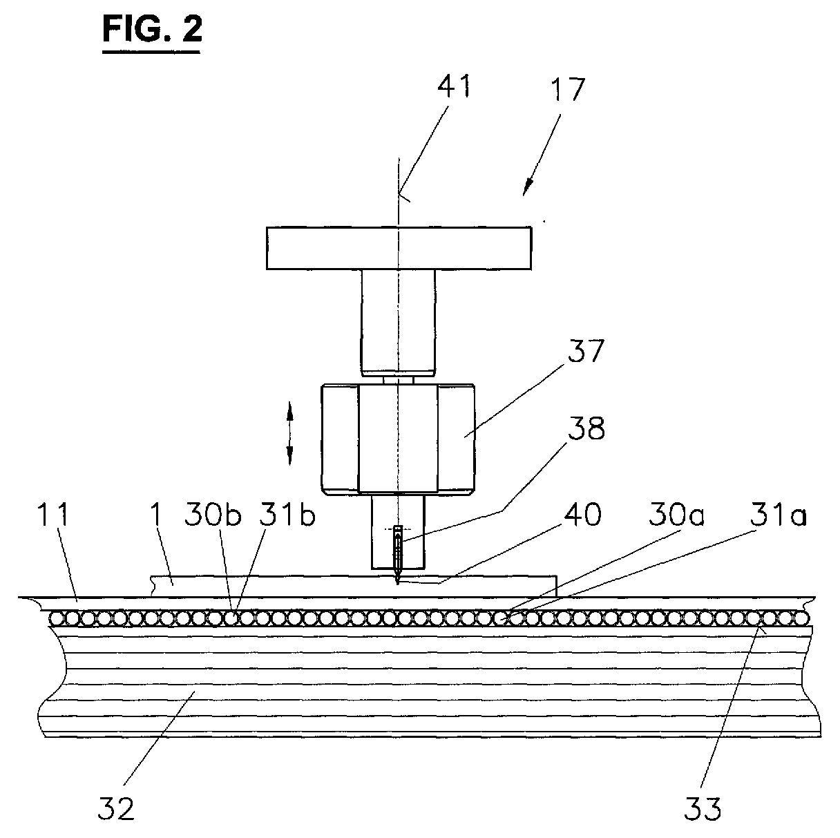
- Fig. 2 shows a side view of the pad, which to processing glass pane 1 supports.
- the glass pane 1 lies directly on the conveyor belt 11, which, for example, from rubber-like material in the form of a mat.
- each one form flexible channel with a cavity 31a and 31b and which run essentially across the conveyor belt 11.
- the Hoses 30a and 30b are relatively elastic and exist for example from a suitable plastic.
- the Cavities 31a and 31b of the hoses can also be used Fill compressed air, for example a compressor (not shown) is used. If the air pressure is high enough the cavities 31a and 31b are the tubes 30a and 30b hardly compressible anymore and thus form a relatively hard one Area.
- the tubes 30a and 30b are on a hard one Fixed table top 32, for example made of metal consists.
- the processing head 16 is located above the conveyor belt 11 the cutting and breaking tool 17 and 18 respectively.
- the Cutting tool 17 includes cutting head 37, which is shown in FIG vertical direction is movable, so that it on the Surface of the glass sheet 1 can be placed. At the There is a cutting wheel at the lower end of the cutting head 38, by means of which the glass pane 1 to be processed has Cut lines 40 is provided.
- the cutting head 37 is rotatable about a vertical axis 41 stored, with the respective orientation of the cutting head 37 and thus the cutting wheel 38 by means of a drive (not shown) can be controlled. This leaves the cutting wheel 38 is substantially parallel to the Align the desired contour of the cutting line 40, with the Driving the cutting line 40, the cutting bridge 14 and the Machining head 16 in the y or x direction accordingly be moved.
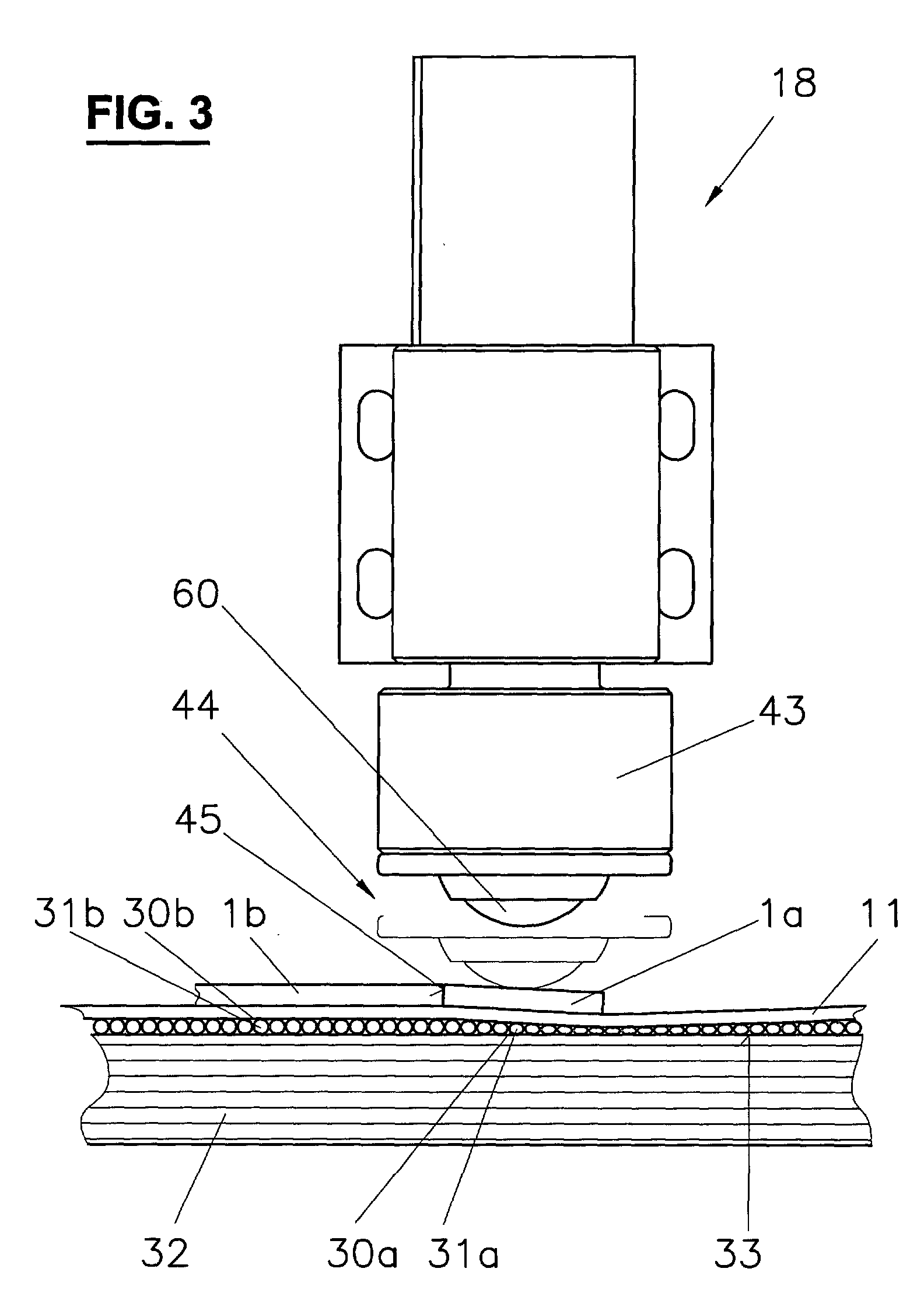
- Fig. 3 shows a side view of the breaking tool 18, with which parts 1a of the cut glass pane 1 cancel.
- the breaking tool 18 is together with the Cutting tool 17 arranged on the machining head 16 and can therefore also be moved in the xy plane. It can also be moved in the vertical direction.
- the Crushing head 43 of the crushing tool 18 can also be used a certain pressure on the part to be separated 1a Press glass pane 1 as shown by lines 44 is shown.
- the pad 30a, 30b, 32 shown in FIG processing glass sheet 1 is the same as that in Fig. 2 shown document.
- breaking the glass 1 corresponds to the air pressure in the tubes 30a, 30b essentially the normal pressure of the environment so that it are relatively flexible and thus the crushing head 43 a certain bending moment on the part 1a to be separated Glass pane 1 can exercise.
- the raw glass sheet 1 is pre-positioned and by means of first transfer device 21 onto the conveyor belt 11 put on and sucked in there. This will be one certain length in the y direction until the glass pane 1 has reached the processing position.
- Compressed air is pressed into the hoses 30a and 30b so that by the pressure in the cavities 31a and 31b a relative hard pad is formed, which is under the Pressure not deformed, the cutting tool 17 when Cutting on the glass pane 1 exercises.
- the cutting tool 17 is placed on the surface of the glass sheet 1 and then provide them with the desired cutting lines 40.
- the orientation of the cutting head 37 is about vertical axis 41 controlled accordingly and the Move machining head 16 in the xy plane.
- the glass pane 1 remains in the same position for breaking leave as in the cutting process. By deflating air the overpressure in the tubes 30a and 30b balanced so that they are now relatively compliant.
- the Air pressure is mainly in those hoses 30a balanced, which is below the edge to be broken off 1a of the glass sheet 1 are.
- the overpressure will leave in the hoses 30b, which in the Mainly support part 1b of the glass pane 1 will continue to be used.
- the breaking head 43 is placed on the surface of the glass pane 1 put on and with a certain pressure along the circumference the cut glass pane. Since the hoses 30a and 30b can now be squeezed together relatively easily, as shown schematically in Fig. 3, there is Edge part 1a of the glass sheet 1 under the pressure of Breaking tool 18 after, the break 45 from the the section lines 40 provided surface propagates opposite glass pane surface.
- the glass pane 1b is then covered with the second Translator 22 transported away, for example to Further processing at a grinding station 23. Die Broken glass from the broken edge part 1a remains on the conveyor belt 11 back. This will be the next Operation moves in the y direction, leaving the broken glass fall down over the drive roller 13 and into be caught in a container.
- Hoses are used that are relatively elastic and are thin-walled. When cutting these are by the Dead weight of the glass pane squeezed together so that the Pressure exerted by the cutting tool essentially is caught directly by the table top. So that Hoses can be compressed using the cavities connected to the ambient air, creating a pressure equalization is made possible.
- the tubes When breaking, the tubes are filled with air, making it a relatively flexible cushion of air between the Form the glass pane and the table top.
- the cavities 31a, 31b instead of air, the cavities 31a, 31b also other types of gases or liquid media (e.g. water), and by regulating the Pressure in the cavities can increase the flexibility of the Document can be controlled.
- gases or liquid media e.g. water
- the table top is in x and y direction with a variety of small pegs provided from a compliant material, for example plastic.
- the cones are in vertically displaceable, the respective End of the tenon at about the same height as the top of the table top 33 or at a certain distance above it comes to lie.
- the pins are in the table top 32 sunk so that the pressure of the cutting tool 17th fields.
- it is therefore relatively flexible Supported base, which is formed by the pin.
- the value of the yield stress can be determined by applying a corresponding electrical or magnetic field set between zero and the maximum value.
- a electrorheological or a magnetorheological Liquid 50 arranged in a relative elastic sleeve 51 is located.
- Suitable electrorheological and magnetorheological Liquids are e.g. available from Lord Corporation, 406 Gregson Drive, Cary, NC 27511, USA or at Bayer AG, D-51368 Leverkusen, Germany.
- An electric field can be created with metal plate pairs generate, each serving as an anode or cathode.
- the table top 32 is on its top in the x and y directions provided with a row of plates 52a, 52b which is, for example, a negative electrical voltage can be created.
- the top of the shell 51 is analogous provided with plates 53a, 53b in the x and y directions which apply a positive electrical voltage can.
- the flexibility of the pad is partially adjustable.
- the glass sheet 1 becomes, for example, the tension between those plate pairs 52a and 53a to zero set, which is essentially below the glass pane edge 1a to be broken off.
- the voltage is, however, between those pairs of plates 52b and 53b, which is essentially the broken-out one Support part 1b of the glass pane. Since this is the case with Breaking process supported by a relatively hard surface is a particularly clean break.
- a suitable magnetic field for example generated by a variety of current loops or coils, with which the magnetorheological fluid 50 in x and y direction is interspersed. Analogously as described above each other by applying a current Current loops or coils the flexibility of the pad partially regulate.
- a To use medium such as water and by means Coolant and heating medium make the transition between liquid and to control the fixed phase.
- the medium is during the cutting process in the solid phase, so that the base which the Glass pane supports is relatively hard.
- the breaking process the medium becomes liquid by supplying energy Phase transferred and so a soft, flexible base created.
- the Breaking tool 18 has a breaking head 43 at the lower end on, in the vertical direction by means of a drive is movable.
- the crushing head 43 includes a ball 60 as well a ball bearing 61. This in turn has a number of smaller balls 62 over which the ball 60 can slide away.
- a ring 63 is mounted, which prevents the Ball bearing 61 and the ball 60 prevented.
- the ball 60 can be freely rotated by means of the ball bearing 61 stored and can be especially around the x and y axes turn freely. This has compared to the known one Crushing tools provided the advantage that no Drive is needed, which along the crushing head the vertical axis.
- the diameter of the ball 60 is preferably in the range from 10 mm to 100 mm and is approximately 30 mm in size, for example.
- Ball 60 has a surface that is harder than glass is.
- a steel ball for example, is suitable.
- the surface of the ball 60 can still with a hard layer, such as Balinit® (Balzers Inc., USA).
- the balinite layer has a thickness of typically a few microns and has one Vickers hardness greater than 1500 HV 0.05 (Vickers hardness measured with a test force of 0.05 pond corresponding to 0.49 N).
- Brownnite layers are made of different materials available: CrN (hardness of approx. 1750 HV 0.05), TiN (approx. 2300 HV 0.05), TiCN (approx. 3000 HV 0.05), TiAlN (approx. 3300 HV 0.05).
- the ball is used to break a cut glass sheet 1 60 with a certain pressure against the glass pane 1 pressed and guided along its circumference by appropriate Control of the breaking tool 18 in the xy plane. there rolls the freely rotatable ball 60 over the surface of the Glass pane 1 without their orientation somehow needs to be controlled, as is the case with a crushing wheel would be necessary.
- the control of the ball 60 can therefore be compared the known devices can be considerably simplified.
- breaking tool 18 not on systems with the limited documents described above.
- Generally can be used to break a glass pane instead of a crushing wheel 4, e.g. in the processes in which the glass sheet with a The template of the desired shape is underlaid so that the part of the glass pane to be separated does not rest and can be broken off by means of the breaking tool 18.
Landscapes
- Chemical & Material Sciences (AREA)
- Engineering & Computer Science (AREA)
- Materials Engineering (AREA)
- Organic Chemistry (AREA)
- Re-Forming, After-Treatment, Cutting And Transporting Of Glass Products (AREA)
Abstract
Description
- Fig. 1
- eine Draufsicht der erfindungsgemässen Anlage,
- Fig. 2
- eine Detail-Seitenansicht der Anlage gemäss Fig. 1 beim Schneiden einer Glasscheibe,
- Fig. 3
- eine Detail-Seitenansicht der Anlage gemäss Fig. 1 beim Brechen einer Glasscheibe und
- Fig. 4
- eine Detail-Seitenansicht einer weiteren Ausführungsform der Anlage beim Brechen einer Glasscheibe.
- Für das Abbrechen des Glasscheibenrandes sind keine Schablonen mehr nötig. Somit können die Bearbeitungskosten erheblich gesenkt werden.
- Die Glasscheiben können bei gleichbleibender Bearbeitungsposition sowohl geschnitten als auch gebrochen werden. Dadurch entfällt ein Neupositionieren der Glasscheiben zwischen den beiden Arbeitsgängen, was eine präzisere Bearbeitung der Glasscheiben ermöglicht.
- Glasscheiben mit verschiedenen Dicken können mit derselben Anlage bearbeitet werden. Die Härte bzw. Nachgiebigkeit der Unterlage lässt sich durch entsprechende Regulierung des Luftdruckes geeignet an die Dicke der Glasscheibe anpassen.
- Maximal anlegbares elektrisches Feld: ca. 5 kV/mm
- maximale Fliessspannung (mechanische Belastung, bei welcher die Flüssigkeit in der S-Phase zu fliessen beginnt): 1-5 kPa
- Viskosität: 0.1-1.0 Pas
- Dichte: 1-2 g/cm3
- Maximal anlegbares magnetisches Feld: ca. 250 kA/m
- maximale Fliessspannung: 50-100 kPa
- Viskosität: 0.1-1.0 Pas
- Dichte: 3-4 g/cm3
- 1
- Glasscheibe
- 1a
- Teil der geschnittenen Glasscheibe 20, der abgebrochen wird
- 1b
- Teil der geschnittenen Glasscheibe 20, der der gewünschten Form entspricht und weiterverwendet wird
- 10
- Schneid- und Brechstation
- 11
- Förderband
- 12
- Umlenkrolle
- 13
- Antriebsrolle
- 14
- Schneidbrücke
- 15
- Führungsschiene
- 16
- Bearbeitungskopf
- 17
- Schneideinrichtung
- 18
- Brecheinrichtung
- 21
- Erste Übersetzvorrichtung
- 22
- Zweite Übersetzvorrichtung
- 23
- Schleifstation
- 30a
- Schlauch
- 30b
- Schlauch
- 31a
- Hohlraum von Schlauch 30a
- 31b
- Hohlraum von Schlauch 30b
- 32
- Tischplatte
- 33
- Oberseite der Tischplatte
- 37
- Schneidkopf
- 38
- Schneidrad
- 40
- Schnittlinie
- 41
- vertikale Achse
- 43
- Brechkopf
- 44
- Vertikale Position des Brechkopfs 43 beim Brechen der Glasscheibe
- 45
- Bruchlinie
- 50
- Elektro-/ Magnetorheologische Flüssigkeit
- 51
- Hülle
- 52a
- Plättchen (Kathode)
- 52b
- Plättchen (Kathode)
- 53a
- Plättchen (Anode)
- 53b
- Plättchen (Anode)
- 60
- Kugel
- 61
- Kugellager
- 62
- Kugel des Kugellagers 61
- 63
- Ring
Claims (16)
- Vorrichtung zur Bearbeitung einer Glasscheibe (1) mit einem Brechwerkzeug (18), das einen Körper (60) aufweist, der zum Brechen der Glasscheibe auf die Oberfläche der Glasscheibe aufsetzbar ist, dadurch gekennzeichnet, dass
der Körper um mindestens zwei Achsen (x, y) frei drehbar gelagert ist. - Vorrichtung gemäss Anspruch 1, dadurch gekennzeichnet, dass der Körper (60) kugelförmig ist.
- Vorrichtung gemäss Anspruch 1 oder 2, dadurch gekennzeichnet, dass der Körper (60) mittels eines Kugellagers (61, 62) gelagert ist.
- Vorrichtung gemäss einem der Ansprüche 1 bis 3, dadurch gekennzeichnet, dass der Körper (60) eine Oberfläche aus Hart-Metall aufweist.
- Vorrichtung gemäss einem der Ansprüche 1 bis 4, dadurch gekennzeichnet, dass das Brechwerkzeug (18) entlang mindestens zweier Achsen (x, y) verfahrbar ist, sodass der Körper (60) zum Brechen entlang der Oberfläche der Glasscheibe (1) verfahrbar ist.
- Vorrichtung zum Stützen einer Glasscheibe (1) bei deren Bearbeitung, insbesondere beim Schneiden und Brechen, welche Vorrichtung eine Unterlage (11; 30a, b; 32; 50) zum Stützen der Glasscheibe umfasst, dadurch gekennzeichnet, dass
die Vorrichtung ferner Reguliermittel (31a, b; 52a, b; 53a, b) aufweist, mit welcher die Flexibilität der Unterlage regulierbar ist, sodass beim Schneiden der Glasscheibe die Unterlage zumindest teilweise starr ist und beim Brechen der Glasscheibe die Unterlage zumindest teilweise nachgiebig ist. - Vorrichtung gemäss Anspruch 6, dadurch gekennzeichnet, dass die Reguliermittel mindestens einen Hohlraum (31a, b) und ein gasförmiges oder flüssiges Medium umfassen, mit welchem der Hohlraum gefüllt werden kann.
- Vorrichtung gemäss Anspruch 7, dadurch gekennzeichnet, dass der Hohlraum durch einen flexiblen Kanal (30a, b) gebildet wird.
- Vorrichtung gemäss Anspruch 6, dadurch gekennzeichnet, dass die Reguliermittel ein Medium (50) umfassen, deren mechanischen Eigenschaften durch Anlegen eines elektrischen oder magnetischen Feldes veränderbar sind.
- Vorrichtung gemäss Anspruch 6, dadurch gekennzeichnet, dass die Reguliermittel ein Medium sowie Kühl- und Heizmittel umfassen, mit welchen ein Phasenübergang des Mediums erzeugbar ist.
- Vorrichtung gemäss Anspruch 6, dadurch gekennzeichnet, dass die Reguliermittel eine Vielzahl von Elementen aus nachgiebigem Material umfassen, die gegen die Glasscheibe (1) führbar sind.
- Vorrichtung gemäss einem der Ansprüche 6 bis 11, dadurch gekennzeichnet, dass die Unterlage eine Matte (11) aus einem nachgiebigen Material umfasst, wobei die Matte vorzugsweise gelocht ist.
- Verfahren zur Bearbeitung von Glasscheiben (1), wobei die Glasscheibe beim Schneiden und Brechen durch eine Unterlage (11; 30a, b; 32; 50) gestützt wird, dadurch gekennzeichnet, dass
die Flexibilität der Unterlage verändert wird, sodass beim Schneiden der Glasscheibe die Unterlage zumindest teilweise starr ist, und beim Brechen der Glasscheibe die Unterlage zumindest teilweise nachgiebig ist. - Verfahren nach Anspruch 13, dadurch gekennzeichnet, dass die Flexibilität der Unterlage mittels mindestens eines Hohlraumes (31a, b) reguliert wird, indem ein gasförmiges oder flüssiges Medium in den Hohlraum hinein oder aus diesem hinaus befördert wird.
- Verfahren nach einem der Ansprüche 13 bis 14, dadurch gekennzeichnet, dass die Glasscheibe (1) bei gleichbleibender Position geschnitten und gebrochen wird.
- Verfahren nach einem der Ansprüche 13 bis 15, dadurch gekennzeichnet, dass die Glasscheibe vor dem Schneiden und Brechen auf eine Matte (11) durch Unterdruck aufgespannt wird.
Applications Claiming Priority (2)
| Application Number | Priority Date | Filing Date | Title |
|---|---|---|---|
| CH16542002 | 2002-10-03 | ||
| EP20021654 | 2002-10-03 |
Publications (2)
| Publication Number | Publication Date |
|---|---|
| EP1367027A2 true EP1367027A2 (de) | 2003-12-03 |
| EP1367027A3 EP1367027A3 (de) | 2004-10-27 |
Family
ID=32963750
Family Applications (1)
| Application Number | Title | Priority Date | Filing Date |
|---|---|---|---|
| EP03405565A Withdrawn EP1367027A3 (de) | 2002-10-03 | 2003-07-28 | Vorrichtung und Verfahren zum Brechen von geritzten Glasscheiben |
Country Status (1)
| Country | Link |
|---|---|
| EP (1) | EP1367027A3 (de) |
Cited By (3)
| Publication number | Priority date | Publication date | Assignee | Title |
|---|---|---|---|---|
| EP1647534A1 (de) * | 2004-10-15 | 2006-04-19 | Bystronic Maschinen AG | Vorrichtung und Verfahren zum Brechen von Glasscheiben |
| DE102012207321A1 (de) * | 2012-05-03 | 2013-11-07 | Robert Bosch Gmbh | Transportvorrichtung mit verbesserten Hafteigenschaften |
| DE102012207326A1 (de) * | 2012-05-03 | 2013-11-07 | Robert Bosch Gmbh | Transportvorrichtung mit magnetorheologischer Flüssigkeit |
Family Cites Families (8)
| Publication number | Priority date | Publication date | Assignee | Title |
|---|---|---|---|---|
| DE2504111C3 (de) * | 1975-01-31 | 1981-11-26 | Borskij Stekol'nyj zavod imeni M. Gor'kogo, Bor, Gorkovskaja oblast' | Vorrichtung zum Ausschneiden von Figuren aus Glastafeln |
| BE830544A (fr) * | 1975-06-23 | 1975-10-16 | Procede automatique pour la decoupe a formes diverses de feuilles de verre et machine destinee a realiser le procede | |
| EP0401161B1 (de) * | 1989-06-01 | 1993-07-21 | Bystronic Maschinen AG | Verfahren und Anlage zur Bearbeitung von Glasscheiben |
| AT399143B (de) * | 1989-06-05 | 1995-03-27 | Lisec Peter | Verfahren und vorrichtung zum zerteilen einer glastafel |
| CH685199A5 (de) * | 1992-05-01 | 1995-04-28 | Bystronic Masch | Plattenschneideverfahren. |
| DE19700950C2 (de) * | 1997-01-14 | 2002-06-06 | Torgauer Maschb Gmbh | Verfahren und Vorrichtung zum Abbrechen der Randstreifen einer nach einem vorgegebenen Umriß auf einem Glasscheibenrohling eingeritzten Glasscheibe |
| JP3088327B2 (ja) * | 1997-03-24 | 2000-09-18 | 鹿児島日本電気株式会社 | ガラス基板分断方法 |
| US6079701A (en) * | 1999-05-24 | 2000-06-27 | Corle; John R. | Glass cutter's table |
-
2003
- 2003-07-28 EP EP03405565A patent/EP1367027A3/de not_active Withdrawn
Cited By (4)
| Publication number | Priority date | Publication date | Assignee | Title |
|---|---|---|---|---|
| EP1647534A1 (de) * | 2004-10-15 | 2006-04-19 | Bystronic Maschinen AG | Vorrichtung und Verfahren zum Brechen von Glasscheiben |
| DE102012207321A1 (de) * | 2012-05-03 | 2013-11-07 | Robert Bosch Gmbh | Transportvorrichtung mit verbesserten Hafteigenschaften |
| DE102012207326A1 (de) * | 2012-05-03 | 2013-11-07 | Robert Bosch Gmbh | Transportvorrichtung mit magnetorheologischer Flüssigkeit |
| US9162820B2 (en) | 2012-05-03 | 2015-10-20 | Robert Bosch Gmbh | Conveyor device with improved adhesive properties |
Also Published As
| Publication number | Publication date |
|---|---|
| EP1367027A3 (de) | 2004-10-27 |
Similar Documents
| Publication | Publication Date | Title |
|---|---|---|
| EP0326819B1 (de) | Vorrichtung zum trockenen Bedrucken eines Werkstücks unter Verwendung einer Heissprägefolie und eines Prägestempels | |
| DE4128933C2 (de) | Stanzvorrichtung | |
| DE102009050533A1 (de) | Verfahren und Warmumformanlage zur Herstellung eines gehärteten, warm umgeformten Werkstücks | |
| DE69507964T2 (de) | Einrichtung zum greifen und fördern von blattmaterial sowie ein damit versehener manipulator | |
| DE10303458A1 (de) | Verfahren und Vorrichtung zum Formen dünner Metallbleche | |
| EP0456121A1 (de) | Verfahren zum Biegen von plattenförmigen Werkstücken sowie Biegemaschine zur Durchführung des Verfahrens | |
| EP0128870B1 (de) | Vorrichtung zum Feinschneiden von Fenstern in einem Kugelkäfig | |
| EP1647534B1 (de) | Vorrichtung und Verfahren zum Brechen von Glasscheiben | |
| DE2219161A1 (de) | Verfahren zur Herstellung von ge wölbten Glasscheiben und Vorrichtung zur Durchführung des Verfahrens | |
| EP1425142A1 (de) | Vorrichtung zur lagerung von flächigen materialien beim trennen mittels einer trenneinrichtung sowie trennverfahren | |
| DE3527558C2 (de) | ||
| DE102023124450A1 (de) | Heizvorrichtung zum Erwärmen einer Platine aus Metall oder Kunststoff und Umformstation für eine Platine aus Metall oder Kunststoff | |
| DE102020202480B4 (de) | Verfahren und Vorrichtung zum Ausrichten von Dünnschichtelementen | |
| EP0692365A1 (de) | Abdeckplatte für Vakuumformmaschinen | |
| DE102008048241A1 (de) | Bearbeitungsvorrichtung für gelötete Werkstücke | |
| EP0105447B1 (de) | Vorrichtung zum Biegen von warmen Glasscheiben | |
| DE102005024378B4 (de) | Verfahren zur inkrementellen Umformung von dünnwandigen Werkstücken sowie Vorrichtung | |
| DE102017118492A1 (de) | Pressenwerkzeug | |
| DE19513444C2 (de) | Vorrichtung zum hydromechanischen Umformen | |
| DE102005036377B4 (de) | Vorrichtung und Verfahren zur Formgebung eines Werkstückes | |
| DE102013209270B4 (de) | Vorrichtung zum Einspannen einer Faseranordnung | |
| EP3981748A1 (de) | Umformvorrichtung zur herstellung von glasprodukten und verfahren | |
| EP1402968A1 (de) | Boerdelvorrichtung | |
| DE4416344C1 (de) | Verfahren zum Herstellen von Hohlkörpern aus zwei verformten Kunststoffplatten und Vorrichtung zur Durchführung des Verfahrens | |
| DE3336660C1 (de) | Vorrichtung zum Herstellen von Löchern in flächenhaftem Material |
Legal Events
| Date | Code | Title | Description |
|---|---|---|---|
| PUAI | Public reference made under article 153(3) epc to a published international application that has entered the european phase |
Free format text: ORIGINAL CODE: 0009012 |
|
| AK | Designated contracting states |
Kind code of ref document: A2 Designated state(s): AT BE BG CH CY CZ DE DK EE ES FI FR GB GR HU IE IT LI LU MC NL PT RO SE SI SK TR |
|
| AX | Request for extension of the european patent |
Extension state: AL LT LV MK |
|
| RIN1 | Information on inventor provided before grant (corrected) |
Inventor name: GFELLER, HANS Inventor name: REBER, BRUNO |
|
| PUAL | Search report despatched |
Free format text: ORIGINAL CODE: 0009013 |
|
| AK | Designated contracting states |
Kind code of ref document: A3 Designated state(s): AT BE BG CH CY CZ DE DK EE ES FI FR GB GR HU IE IT LI LU MC NL PT RO SE SI SK TR |
|
| AX | Request for extension of the european patent |
Extension state: AL LT LV MK |
|
| AKX | Designation fees paid | ||
| REG | Reference to a national code |
Ref country code: DE Ref legal event code: 8566 |
|
| STAA | Information on the status of an ep patent application or granted ep patent |
Free format text: STATUS: THE APPLICATION IS DEEMED TO BE WITHDRAWN |
|
| 18D | Application deemed to be withdrawn |
Effective date: 20050428 |