EP1365502B1 - Phase detector for quadrature signals, and method - Google Patents
Phase detector for quadrature signals, and method Download PDFInfo
- Publication number
- EP1365502B1 EP1365502B1 EP03009580A EP03009580A EP1365502B1 EP 1365502 B1 EP1365502 B1 EP 1365502B1 EP 03009580 A EP03009580 A EP 03009580A EP 03009580 A EP03009580 A EP 03009580A EP 1365502 B1 EP1365502 B1 EP 1365502B1
- Authority
- EP
- European Patent Office
- Prior art keywords
- quadrature
- signal
- elapsed time
- pair
- time periods
- Prior art date
- Legal status (The legal status is an assumption and is not a legal conclusion. Google has not performed a legal analysis and makes no representation as to the accuracy of the status listed.)
- Expired - Lifetime
Links
- 238000000034 method Methods 0.000 title claims description 43
- 230000007704 transition Effects 0.000 claims description 19
- 230000008859 change Effects 0.000 claims description 10
- 230000008569 process Effects 0.000 description 26
- 230000005540 biological transmission Effects 0.000 description 6
- 238000010586 diagram Methods 0.000 description 5
- 238000006073 displacement reaction Methods 0.000 description 4
- 238000005259 measurement Methods 0.000 description 3
- 230000003287 optical effect Effects 0.000 description 3
- 230000005355 Hall effect Effects 0.000 description 2
- 230000007246 mechanism Effects 0.000 description 2
- 108010076504 Protein Sorting Signals Proteins 0.000 description 1
- 230000009471 action Effects 0.000 description 1
- 230000008901 benefit Effects 0.000 description 1
- 230000001934 delay Effects 0.000 description 1
- 230000001419 dependent effect Effects 0.000 description 1
- 238000001514 detection method Methods 0.000 description 1
- 238000011161 development Methods 0.000 description 1
- 230000018109 developmental process Effects 0.000 description 1
- 230000004048 modification Effects 0.000 description 1
- 238000012986 modification Methods 0.000 description 1
- 230000007935 neutral effect Effects 0.000 description 1
- 230000004044 response Effects 0.000 description 1
- 238000010200 validation analysis Methods 0.000 description 1
Images


Classifications
-
- G—PHYSICS
- G05—CONTROLLING; REGULATING
- G05B—CONTROL OR REGULATING SYSTEMS IN GENERAL; FUNCTIONAL ELEMENTS OF SUCH SYSTEMS; MONITORING OR TESTING ARRANGEMENTS FOR SUCH SYSTEMS OR ELEMENTS
- G05B9/00—Safety arrangements
- G05B9/02—Safety arrangements electric
-
- G—PHYSICS
- G01—MEASURING; TESTING
- G01P—MEASURING LINEAR OR ANGULAR SPEED, ACCELERATION, DECELERATION, OR SHOCK; INDICATING PRESENCE, ABSENCE, OR DIRECTION, OF MOVEMENT
- G01P21/00—Testing or calibrating of apparatus or devices covered by the preceding groups
- G01P21/02—Testing or calibrating of apparatus or devices covered by the preceding groups of speedometers
-
- H—ELECTRICITY
- H03—ELECTRONIC CIRCUITRY
- H03D—DEMODULATION OR TRANSFERENCE OF MODULATION FROM ONE CARRIER TO ANOTHER
- H03D13/00—Circuits for comparing the phase or frequency of two mutually-independent oscillations
Definitions
- This invention relates to the field of signal validation.
- this invention is drawn to a system for validating quadrature signals generated by sensors in a steering control system.
- sensors In control systems, it is common to use sensors to generate signals relating to various conditions in the system. The sensor signals can then used by the control system in any desired way. For example, in a steering control system, various conditions are sensed (e.g., wheel speed, motor speed, steering wheel speed and position, etc.) and used by the steering control system. It is therefore important that signals generated by sensors are accurate in order to describe what is occurring in the system.
- both signals should have nearly a 50% duty cycle and be nearly 90 degrees out of phase. These characteristics ensure that a microprocessor in a control system will have enough time to decode the signals, and to provide correct measurement of speed and direction of a sensed object.
- EP 0 339 611 A2 discloses a steering control system using a quadrature signal pair provided by a sensor.
- the quadrature signals may not meet the desired duty cycle and phase requirements. This may be due to several factors. For example, the sensor may be misaligned, causing the duty cycle of the signals to be much greater or much less than 50%. Misalignment may also cause the signals to be more or less than 90 degrees out of phase. Also, the sensor itself may fail, or may not be capable of producing quadrature under all conditions. For example, some sensors produce correct quadrature only when the object they are sensing is rotating at a particular speed. Also, propagation delays from electronic circuitry may alter the phase relationship of the signals.
- quadrature signals should be evaluated for accuracy and validity.
- the present invention provides a system and method for validating quadrature signals.
- Figure 1 illustrates one example of an environment in which the present invention may be used. As described in more detail below, the present invention may also be used in other applications and environments that utilize quadrature signals.
- FIG. 1 shows a simplified schematic diagram of a tracked vehicle drive and steering system.
- an engine 10 of a tracked vehicle has an output shaft 12 which drives a right angle gear 14 and a transmission 16, such as a 16-speed powershift transmission which is available on production John Deere 8000T tractors.
- the transmission 16 includes hydraulically operated clutches and brakes (not shown), various ones of which will operate as a main clutch 18 in response to a conventional clutch pedal and linkage (not shown).
- the engine 10 is controlled by an electronic engine control unit 11.
- the transmission 16 drives a final or right angle drive 20, which drives a left track drive wheel 22 via left steering planetary drive 24, and a right track drive wheel 26 via right steering planetary drive 28.
- the steering planetary drives 24 and 28 are preferably such as described in US-5,390,751 . Additional outboard planetaries (not shown), as provided on John Deere 8000T tractors, are mounted between the steering planetaries and the respective drive wheels, but are not further described because they are not directly involved in the subject matter of this application.
- a parking brake 30 is coupled to the output shaft of transmission 16, and left and right service brakes 32, 34 are coupled to the left and right drive wheels 22, 26, respectively.
- the right angle gear 14 drives a variable displacement steering pump 40, such as a 75 cc, 90 series pump made by Sauer-Danfoss.
- the pump 40 powers a hydraulic fixed displacement steering motor 42, such as a 75 cc, 90 series motor, also made by Sauer-Danfoss Inc.
- the steering motor 42 drives, via a cross shaft 44 and gear 46, a ring gear 47 of left planetary drive 24, and via cross shaft 44, gear 48 and reverser gear 50, a ring gear 52 of right planetary drive 28.
- the steering pump 40 has a swashplate (not shown), the position of which is controlled by a swashplate control valve or electronic displacement control (EDC) 60.
- EDC electronic displacement control
- the EDC is preferably a two stage device with first stage including a flapper type valve operated by a pair of solenoids 59, 61, and a second stage including a boost stage to the pump, such as is used on the production John Deere 8000T Series tracked tractor.
- An engine speed sensor 62 such as a commercially available variable reluctance sensor, provides an engine speed signal to a steering system unit (SSU) 70.
- the solenoids 59, 61 of valve 60 are controlled by pulse-width-modulated (PWM) pump control signals generated by SSU 70.
- PWM pulse-width-modulated
- An operator controlled steering wheel 74 is preferably connected to a non-spring centered input mechanism 72, such as described in US-6,000,490 .
- the input mechanism 72 includes an electro-magnetically controlled friction device or brake 75 and a rotary position transducer or incremental encoder 77, such as a commercially available Grayhill Series 63R encoder or an OakGrigsby 900 Optical Encoder.
- the encoder 77 provides to SSU 70 a steering wheel position signal representing the position of operator controlled steering wheel 74.
- the encoder 77 generates a plurality, preferably 128, of pulses per each revolution of the steering wheel 74.
- the SSU 70 then repeatedly generates and updates a COUNT value representing the number of optical encoder pulses corresponding to the actual position of the steering wheel 74 relative to the position of the steering wheel 74 at start-up.
- a COUNT value representing the number of optical encoder pulses corresponding to the actual position of the steering wheel 74 relative to the position of the steering wheel 74 at start-up.
- This description relates to a steering input device with a non-spring centered neutral position, but the present invention could also be applied to a system with a spring-centered steering input device.
- the SSU 70 also receives signals from gear shift lever transducer 73, such as described in US-5,406,860 .
- a drive line rotation speed sensor 76 preferably a differential Hall-effect speed sensor such as used on production John Deere 8000T tractors, is mounted in proximity to the final drive 20, and provides to the SSU 70 a variable frequency final drive speed or wheel speed signal.
- a magnetic ring 78 is mounted for rotation with the motor 42, and a Hall-effect transducer 80 mounted near the magnetic ring 78 provides to the SSU 70 a quadature signal pair.
- a pair of clutch status switches 82 are located within the transmission 16 and are operatively associated with the linkage (not shown) between the clutch pedal (not shown) and the main clutch 18, and provide a clutch status signal to the SSU 70.
- the SSU 70 includes one or more commercially available microprocessors (not shown in Figure 1) which perform various functions, such as steering control.
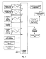
- FIG. 2 is a block diagram showing an example of the use of sensors that generate quadrature signals in a steering control environment, similar to the environment shown in Figure 1.
- Figure 2 shows a steering control unit (SCU) 84, which is provided by a microprocessor that may be a part of a steering system unit, such as SSU 70 described above.
- a wheel speed sensor 86 is provided by a quadrature encoder that generates two data signals (A and B), which are provided to the SCU 84.
- a motor speed sensor 88 also provides quadrature signals to the SCU 84.
- Figure 2 also shows first and second quadrature steering input devices 90 and 92 operatively coupled to a steering wheel 94. The devices 90 and 92 each provide a pair of quadrature signals to the SCU 84.
- Various other components of a steering control system are also shown in Figure 2, although none are essential to the operation of the present invention.
- One or more of the sensors in a control system may be provided by an incremental optical encoder (or any other type of sensor that generates quadrature signals) that generates two data signals that are 90 degrees out of phase with each other, and have a 50% duty cycle. Each data signal contains two voltage transitions, or edges, per cycle. Therefore, an encoder that generates 128 cycles per revolution provides 512 transitions per revolution.
- the quadrature signals can provide a control system information relating to speed and displacement (e.g., the rate and number of transitions).
- the phase difference between the quadrature signals can provide information relating to direction. For example, forward travel can be detected if the first signal lags the second signal by 90 degrees (or vise versa). Similarly, reverse travel can be detected if the second signal lags the first signal by 90 degrees (or vise versa).
- a system can look at changes of state (i.e., the point where a signal transitions from one voltage to another).
- a system can sample the states of the first and second quadrature signals and make a determination of the direction of travel based state transitions.
- Table I provides one example of how a system can make a determination of direction based on state transitions, where the states of the two signals are identified as either high (1) or low (0).
- TABLE I Reverse Direction Forward Direction Previous Present Previous Present 0,1 0,0 0,1 1,1 1,1 0,1 1,1 1,0 1,0 1,1 1,0 0,0 0,0 0,0 0,1 0,1
- Table I provides one example of how a system can make a determination of direction based on state transitions, where the states of the two signals are identified as either high (1) or low (0).
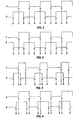
- Figures 3-6 show examples of quadrature signal pairs.
- Figure 3 shows a pair of quadrature signals having a desired duty cycle of 50% and a phase difference of 90 degrees.
- Figure 4 also shows a pair of quadrature signals having a desired duty cycle of 50% and a phase difference of 90 degrees.
- the second signal (B) lags the first signal (A) by 90 degrees.
- the second signal (B) leads the first signal (A) by 90 degrees.
- Table I the signals in Figure 3 show forward travel and the signals in Figure 4 show reverse travel.
- Figure 5 shows signals A and B that do not have a 50% duty cycle.
- Figure 6 shows signals A and B that are not 90 degrees out of phase.
- Figures 5 and 6 are examples of signals that correctly indicate speed and direction but do not meet requirements for complete confidence. Thus, the microprocessor considers them not to be valid. Should the phase relationship or duty cycle become even worse, for example, if the signal sequence becomes BB, AA, BB, AA, etc., such signals convey the speed of the sensed device but do not convey the direction, and are unusable for a control system.
- the present invention provides a way of determining whether the quadrature signals generated by a sensor are valid.
- a system makes a determination of validity by looking at when the signals change states, or transition from one voltage level to another. To accomplish this, the amount of time that elapses between successive transitions is compared to the amount of time that elapses in an adjacent time period. If the two time periods are close enough, the signals are considered reliable and therefore valid. With this information, the system can then be confident it is responding only to valid sensor information. When the quadrature information is not reliable, the system can provide diagnostic information to the user, so that sensors can be adjusted or replaced.
- each edge, or transition point is shown by arrows and labeled "A" or "B".
- the duty cycle is 50% and the phase difference is 90 degrees, the times between successive edges are approximately equal.
- the duty cycle is not 50%, the times between successive edges are not equal ( Figure 5).
- the phase difference is not 90 degrees, the times between successive edges are also not equal ( Figure 6).
- the present invention takes advantage of this fact to validate quadrature signals.
- the invention looks at three successive edges (e.g., A,B,A or B,A,B) of the quadrature pair to determine two adjacent elapsed time values (e.g., A-B, B-A or B-A, A-B).
- the two elapsed time values are compared, and if sufficiently different, the quadrature signals are considered invalid.
- the standards used to make determinations of validity depend on many factors, including desired levels of accuracy and the accuracy of sensors used. In one example, if the difference between two successive elapsed time values is greater than 50% of the lower elapsed time value, the quadrature lines are considered invalid. In another example, the quadrature pair can be provided a confidence factor, depending on the comparison, rather than simply being labeled "valid" or "invalid".
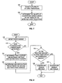
- Figures 7 and 8 are flow charts illustrating examples of the operation of the present invention.
- Figure 7 shows a process starting with step 102, where a plurality of state transitions is detected in a quadrature signal pair. The process ends at step 104, where the validity of the quadrature signal pair is determined based on the timing of the detected state transitions.
- Figure 8 shows a more detailed process.
- a state change or voltage transition, etc.
- the process asks whether three consecutive states changes have been detected (e.g., A,B,A or B,A,B). If not, the process goes back to step 110 where another state change is detected.
- step 114 a first elapsed time between the first and second state changes is determined.
- this step refers to the measurement of elapsed time from a first edge to a second edge (A-B or B-A).
- step 116 a second elapsed time between the second and third state changes is determined.
- this step refers to the measurement of elapsed time from the second edge to a third edge (B-A or A-B).
- the process asks whether the first and second elapsed times differ by a threshold amount.
- the threshold can be defined as a percentage of one of the elapsed time values. In other examples, the threshold can be defined in other ways, such as a minimum elapsed time between transition. If the first and second elapsed times do not differ by more than the threshold amount, the process proceeds to step 120 where the quadrature signals are declared valid. If the first and second elapsed times do differ by at least the threshold amount, the process proceeds to step 122 where the quadrature signals are declared invalid.
- the processes illustrated in Figures 7 and 8 may repeat continuously, or may be repeated as desired.
- the quadrature signals are evaluated by software running in a microprocessor, such as the SCU 84 shown in Figure 2.
- Figures 9-11 are flowcharts illustrating one example of how the present invention may be implemented using software.
- Figure 9 illustrates a quadrature line's interrupt routine. The routine shown in Figure 9 starts at step 130, where the other line's interrupt enabled/disabled status is saved. Next, at step 132, the other line's interrupt is disabled. At step 134, the quadrature edge counter is incremented. The edge counter keeps track of the number of edges since 3 edges are required for the main routine. At step 136, the process checks the last interrupt that occurred.
- step 138 the edge counter is set to 1 and the process proceeds to step 140. If the last line that interrupted was not the same as the current line, the process proceeds to step 140.
- step 140 the time stamps are saved (previous time stamp and previous previous time stamp) and a new time stamp is recorded.
- step 142 the other interrupt line is restored to the original enabled/disabled state.
- FIG. 10 is a flowchart of the main fault detection algorithm.
- the process begins with step 150, where local variables are declared.
- the variables may include the quadrature edge counter, time stamps (current time, previous time, previous previous time), etc..
- step 152 the enabled/disabled state of both quadrature lines are saved.
- step 154 the quadrature interrupts are disabled.
- step 156 a snapshot of the variables set in the interrupt routine is taken.
- step 158 the interrupts are restored to their previous states.
- the process asks whether there have been 3 consecutive quadrature edges (e.g., A-B-A or B-A-B). If not, the process proceeds to step 162 and the previous elapsed time is set to 0.
- quadrature edges e.g., A-B-A or B-A-B
- step 166 the process proceeds to step 164 where the previous elapsed time value is calculated using the previous time stamp and the previous previous time stamp.
- step 166 the process asks whether it has been a long time since an edge has been detected. If so, the process proceeds to step 168 where the previous elapsed time value is set to 0 and the edge counter is reset. If not, the process proceeds to step 170 where the function IsQuadCorrect() (see Figure 11) is called. The function returns "True” for a correct quadrature relationship, otherwise "False”. At step 172, a fault is reported if "False" was returned, otherwise, no action is taken.
- FIG 11 is a flowchart of the function IsQuadCorrect(), called in step 170, described above.
- the process begins with step 180, where the current elapsed time is calculated using the current time stamp and the previous time stamp values captured from the interrupts.
- the process asks if the previous elapsed time is equal to 0. If so, the process proceeds to step 184, where the function exits and returns the value "True” (because not enough data has been collected). If not, the process proceeds to step 186, where the previous elapsed time is compared to the current elapsed time. "False" is returned to the main algorithm if the difference is more than a threshold amount. Otherwise, "True” is returned.
Landscapes
- Physics & Mathematics (AREA)
- General Physics & Mathematics (AREA)
- Engineering & Computer Science (AREA)
- Automation & Control Theory (AREA)
- Power Engineering (AREA)
- Steering Control In Accordance With Driving Conditions (AREA)
- Power Steering Mechanism (AREA)
- Transmission And Conversion Of Sensor Element Output (AREA)
- Control Of Position, Course, Altitude, Or Attitude Of Moving Bodies (AREA)
Applications Claiming Priority (2)
| Application Number | Priority Date | Filing Date | Title |
|---|---|---|---|
| US139416 | 2002-05-06 | ||
| US10/139,416 US6763294B2 (en) | 2002-05-06 | 2002-05-06 | System and method for validating quadrature signals |
Publications (3)
| Publication Number | Publication Date |
|---|---|
| EP1365502A2 EP1365502A2 (en) | 2003-11-26 |
| EP1365502A3 EP1365502A3 (en) | 2004-04-14 |
| EP1365502B1 true EP1365502B1 (en) | 2008-01-23 |
Family
ID=29269541
Family Applications (1)
| Application Number | Title | Priority Date | Filing Date |
|---|---|---|---|
| EP03009580A Expired - Lifetime EP1365502B1 (en) | 2002-05-06 | 2003-04-29 | Phase detector for quadrature signals, and method |
Country Status (7)
| Country | Link |
|---|---|
| US (1) | US6763294B2 (enExample) |
| EP (1) | EP1365502B1 (enExample) |
| JP (1) | JP2004045382A (enExample) |
| AU (1) | AU2003203762B2 (enExample) |
| BR (1) | BR0301040B1 (enExample) |
| CA (1) | CA2424179C (enExample) |
| DE (1) | DE60318767T2 (enExample) |
Families Citing this family (2)
| Publication number | Priority date | Publication date | Assignee | Title |
|---|---|---|---|---|
| DE102007030431A1 (de) * | 2007-06-29 | 2009-01-02 | Continental Teves Ag & Co. Ohg | Verfahren zur Fahrtrichtungserkennung eines Kraftfahrzeugs |
| US8364436B2 (en) | 2009-10-21 | 2013-01-29 | GM Global Technology Operations LLC | Systems and methods for measuring vehicle speed |
Family Cites Families (13)
| Publication number | Priority date | Publication date | Assignee | Title |
|---|---|---|---|---|
| US4865144A (en) * | 1988-04-29 | 1989-09-12 | Eaton Corporation | Power steering system having simulated torque sensor |
| US5406860A (en) | 1993-12-01 | 1995-04-18 | Deere & Company | Transmission shift lever assembly |
| EP0905909B1 (en) * | 1997-09-29 | 2005-12-07 | Texas Instruments Incorporated | Phase locked loop and method of recovering a clock signal |
| US6000490A (en) | 1997-12-17 | 1999-12-14 | Deere & Company | Steering input device |
| US6039132A (en) | 1998-04-01 | 2000-03-21 | Deere & Company | Steering control system for tracked vehicle |
| US6215119B1 (en) * | 1999-01-19 | 2001-04-10 | Xerox Corporation | Dual sensor encoder to counter eccentricity errors |
| EP1216475A1 (en) * | 1999-09-17 | 2002-06-26 | Delphi Technologies, Inc. | Method and apparatus for robust generation of an index pulse for an electric power steering system |
| US6298931B1 (en) | 1999-12-09 | 2001-10-09 | Deere & Company | Tracked vehicle steering control system with non-centered steering wheel |
| US6208922B1 (en) | 1999-12-09 | 2001-03-27 | Deere & Company | Tracked vehicle closed loop steering system |
| JP2003526984A (ja) * | 2000-03-07 | 2003-09-09 | コーニンクレッカ フィリップス エレクトロニクス エヌ ヴィ | データクロックト回復回路 |
| US6345674B1 (en) | 2000-08-23 | 2002-02-12 | Deere & Company | Tracked vehicle steering control system with steering pump feedback |
| US6469499B2 (en) * | 2001-02-06 | 2002-10-22 | Delphi Technologies, Inc. | Apparatus and method for low power position sensing systems |
| US6757635B2 (en) * | 2001-12-12 | 2004-06-29 | Balluff, Inc. | Programmed method and apparatus for quadrature output sensors |
-
2002
- 2002-05-06 US US10/139,416 patent/US6763294B2/en not_active Expired - Lifetime
-
2003
- 2003-03-31 CA CA002424179A patent/CA2424179C/en not_active Expired - Fee Related
- 2003-04-17 AU AU2003203762A patent/AU2003203762B2/en not_active Ceased
- 2003-04-29 BR BRPI0301040-6A patent/BR0301040B1/pt not_active IP Right Cessation
- 2003-04-29 DE DE60318767T patent/DE60318767T2/de not_active Expired - Lifetime
- 2003-04-29 EP EP03009580A patent/EP1365502B1/en not_active Expired - Lifetime
- 2003-05-06 JP JP2003128033A patent/JP2004045382A/ja active Pending
Also Published As
| Publication number | Publication date |
|---|---|
| DE60318767T2 (de) | 2008-07-17 |
| BR0301040A (pt) | 2004-08-17 |
| US6763294B2 (en) | 2004-07-13 |
| DE60318767D1 (de) | 2008-03-13 |
| EP1365502A3 (en) | 2004-04-14 |
| EP1365502A2 (en) | 2003-11-26 |
| JP2004045382A (ja) | 2004-02-12 |
| CA2424179C (en) | 2006-07-04 |
| AU2003203762B2 (en) | 2007-07-12 |
| AU2003203762A1 (en) | 2003-11-27 |
| BR0301040B1 (pt) | 2012-05-02 |
| US20030208310A1 (en) | 2003-11-06 |
| CA2424179A1 (en) | 2003-11-06 |
Similar Documents
| Publication | Publication Date | Title |
|---|---|---|
| US7472004B2 (en) | Steering angle sensor | |
| US7565947B2 (en) | Vehicular steering system | |
| EP1746392B1 (en) | Phase detection circuit, resolver/digital converter using the circuit, method performing digital conversion of an analog signal, and control system using the converter | |
| CN1201138C (zh) | 变速器输出轴每分钟转数传感器的故障诊断方法及系统 | |
| EP0232009A1 (en) | Power steering apparatus and control system for power steering apparatus having a steering wheel angle detection device | |
| JP2000296781A (ja) | 電動パワー・ステアリング・システムに関する改良 | |
| EP2864738B1 (en) | Method of processing sensor signals for determining motion of a motor shaft | |
| US12352777B2 (en) | Control circuit for a sensor, an electrical control unit for a wheel speed sensor, a method of operating a wheel speed sensor, a method of controlling a sensor and a computer program | |
| US5276722A (en) | Absolute multi-revolution encoder | |
| EP1365502B1 (en) | Phase detector for quadrature signals, and method | |
| JP2015087118A (ja) | 異常診断装置及びそれを用いたシフトバイワイヤ装置 | |
| EP1088742A3 (en) | Tracked vehicle steering system with failure detection | |
| JP5156229B2 (ja) | 高い情報密度で信号を伝送する方法、および、制御装置 | |
| EP1281972A2 (en) | Vehicle speed diagnostic algorithm for four-wheel steering systems | |
| US7603922B2 (en) | Method of correcting shift position sensor of vehicle | |
| JP3067506B2 (ja) | 自動変速機のレンジ切換弁の自走検出装置 | |
| JPH06227062A (ja) | シリアルプリンタ及びシリアルプリンタの制御方法 | |
| US7096994B2 (en) | Method of controlling recovery in electric power steering system | |
| JP3772662B2 (ja) | エンコーダ異常検出装置 | |
| JP2789571B2 (ja) | 車両用制御装置 | |
| KR100459020B1 (ko) | 차량의 조향각 확인장치 | |
| CN208376013U (zh) | 3d打印机运行机构自动消回差和防止错位的装置 | |
| CN115370739A (zh) | 用于运行驻车锁止器系统的方法和控制装置 | |
| JPH08152335A (ja) | リニアエンコーダ | |
| KR100498694B1 (ko) | 조향각 확인이 가능한 동력조향장치 |
Legal Events
| Date | Code | Title | Description |
|---|---|---|---|
| PUAI | Public reference made under article 153(3) epc to a published international application that has entered the european phase |
Free format text: ORIGINAL CODE: 0009012 |
|
| AK | Designated contracting states |
Kind code of ref document: A2 Designated state(s): AT BE BG CH CY CZ DE DK EE ES FI FR GB GR HU IE IT LI LU MC NL PT RO SE SI SK TR |
|
| AX | Request for extension of the european patent |
Extension state: AL LT LV MK |
|
| PUAL | Search report despatched |
Free format text: ORIGINAL CODE: 0009013 |
|
| AK | Designated contracting states |
Kind code of ref document: A3 Designated state(s): AT BE BG CH CY CZ DE DK EE ES FI FR GB GR HU IE IT LI LU MC NL PT RO SE SI SK TR |
|
| AX | Request for extension of the european patent |
Extension state: AL LT LV MK |
|
| 17P | Request for examination filed |
Effective date: 20041014 |
|
| AKX | Designation fees paid |
Designated state(s): BE DE FR GB IT |
|
| 17Q | First examination report despatched |
Effective date: 20050614 |
|
| 17Q | First examination report despatched |
Effective date: 20050614 |
|
| GRAP | Despatch of communication of intention to grant a patent |
Free format text: ORIGINAL CODE: EPIDOSNIGR1 |
|
| GRAS | Grant fee paid |
Free format text: ORIGINAL CODE: EPIDOSNIGR3 |
|
| GRAA | (expected) grant |
Free format text: ORIGINAL CODE: 0009210 |
|
| AK | Designated contracting states |
Kind code of ref document: B1 Designated state(s): BE DE FR GB IT |
|
| REG | Reference to a national code |
Ref country code: GB Ref legal event code: FG4D |
|
| REF | Corresponds to: |
Ref document number: 60318767 Country of ref document: DE Date of ref document: 20080313 Kind code of ref document: P |
|
| PGFP | Annual fee paid to national office [announced via postgrant information from national office to epo] |
Ref country code: BE Payment date: 20080527 Year of fee payment: 6 |
|
| PLBE | No opposition filed within time limit |
Free format text: ORIGINAL CODE: 0009261 |
|
| STAA | Information on the status of an ep patent application or granted ep patent |
Free format text: STATUS: NO OPPOSITION FILED WITHIN TIME LIMIT |
|
| 26N | No opposition filed |
Effective date: 20081024 |
|
| BERE | Be: lapsed |
Owner name: DEERE & CY Effective date: 20090430 |
|
| PG25 | Lapsed in a contracting state [announced via postgrant information from national office to epo] |
Ref country code: BE Free format text: LAPSE BECAUSE OF NON-PAYMENT OF DUE FEES Effective date: 20090430 |
|
| PGFP | Annual fee paid to national office [announced via postgrant information from national office to epo] |
Ref country code: GB Payment date: 20140428 Year of fee payment: 12 |
|
| PGFP | Annual fee paid to national office [announced via postgrant information from national office to epo] |
Ref country code: IT Payment date: 20140428 Year of fee payment: 12 Ref country code: FR Payment date: 20140417 Year of fee payment: 12 Ref country code: DE Payment date: 20140319 Year of fee payment: 12 |
|
| REG | Reference to a national code |
Ref country code: DE Ref legal event code: R119 Ref document number: 60318767 Country of ref document: DE |
|
| GBPC | Gb: european patent ceased through non-payment of renewal fee |
Effective date: 20150429 |
|
| PG25 | Lapsed in a contracting state [announced via postgrant information from national office to epo] |
Ref country code: DE Free format text: LAPSE BECAUSE OF NON-PAYMENT OF DUE FEES Effective date: 20151103 Ref country code: IT Free format text: LAPSE BECAUSE OF NON-PAYMENT OF DUE FEES Effective date: 20150429 Ref country code: GB Free format text: LAPSE BECAUSE OF NON-PAYMENT OF DUE FEES Effective date: 20150429 |
|
| REG | Reference to a national code |
Ref country code: FR Ref legal event code: ST Effective date: 20151231 |
|
| PG25 | Lapsed in a contracting state [announced via postgrant information from national office to epo] |
Ref country code: FR Free format text: LAPSE BECAUSE OF NON-PAYMENT OF DUE FEES Effective date: 20150430 |