EP1364899B1 - Méthode pour transporter des produits plats et flexibles, et dispositif pour mettre en oeuvre la méthode - Google Patents
Méthode pour transporter des produits plats et flexibles, et dispositif pour mettre en oeuvre la méthode Download PDFInfo
- Publication number
- EP1364899B1 EP1364899B1 EP03003301A EP03003301A EP1364899B1 EP 1364899 B1 EP1364899 B1 EP 1364899B1 EP 03003301 A EP03003301 A EP 03003301A EP 03003301 A EP03003301 A EP 03003301A EP 1364899 B1 EP1364899 B1 EP 1364899B1
- Authority
- EP
- European Patent Office
- Prior art keywords
- transfer region
- grippers
- products
- conveying
- product
- Prior art date
- Legal status (The legal status is an assumption and is not a legal conclusion. Google has not performed a legal analysis and makes no representation as to the accuracy of the status listed.)
- Expired - Lifetime
Links
- 238000000034 method Methods 0.000 title claims abstract description 17
- 238000012546 transfer Methods 0.000 claims abstract description 42
- 238000013459 approach Methods 0.000 claims description 11
- 238000011144 upstream manufacturing Methods 0.000 claims description 4
- 238000000151 deposition Methods 0.000 description 4
- 230000015572 biosynthetic process Effects 0.000 description 3
- 230000005484 gravity Effects 0.000 description 2
- 230000001419 dependent effect Effects 0.000 description 1
- 238000013461 design Methods 0.000 description 1
- 238000011161 development Methods 0.000 description 1
- 230000018109 developmental process Effects 0.000 description 1
Images

Classifications
-
- B—PERFORMING OPERATIONS; TRANSPORTING
- B65—CONVEYING; PACKING; STORING; HANDLING THIN OR FILAMENTARY MATERIAL
- B65H—HANDLING THIN OR FILAMENTARY MATERIAL, e.g. SHEETS, WEBS, CABLES
- B65H29/00—Delivering or advancing articles from machines; Advancing articles to or into piles
- B65H29/66—Advancing articles in overlapping streams
- B65H29/6609—Advancing articles in overlapping streams forming an overlapping stream
-
- B—PERFORMING OPERATIONS; TRANSPORTING
- B65—CONVEYING; PACKING; STORING; HANDLING THIN OR FILAMENTARY MATERIAL
- B65H—HANDLING THIN OR FILAMENTARY MATERIAL, e.g. SHEETS, WEBS, CABLES
- B65H29/00—Delivering or advancing articles from machines; Advancing articles to or into piles
- B65H29/003—Delivering or advancing articles from machines; Advancing articles to or into piles by grippers
-
- B—PERFORMING OPERATIONS; TRANSPORTING
- B65—CONVEYING; PACKING; STORING; HANDLING THIN OR FILAMENTARY MATERIAL
- B65H—HANDLING THIN OR FILAMENTARY MATERIAL, e.g. SHEETS, WEBS, CABLES
- B65H2301/00—Handling processes for sheets or webs
- B65H2301/40—Type of handling process
- B65H2301/42—Piling, depiling, handling piles
- B65H2301/422—Handling piles, sets or stacks of articles
- B65H2301/4224—Gripping piles, sets or stacks of articles
- B65H2301/42242—Gripping piles, sets or stacks of articles by acting on the outermost articles of the pile for clamping the pile
-
- B—PERFORMING OPERATIONS; TRANSPORTING
- B65—CONVEYING; PACKING; STORING; HANDLING THIN OR FILAMENTARY MATERIAL
- B65H—HANDLING THIN OR FILAMENTARY MATERIAL, e.g. SHEETS, WEBS, CABLES
- B65H2301/00—Handling processes for sheets or webs
- B65H2301/40—Type of handling process
- B65H2301/44—Moving, forwarding, guiding material
- B65H2301/447—Moving, forwarding, guiding material transferring material between transport devices
- B65H2301/4471—Grippers, e.g. moved in paths enclosing an area
- B65H2301/44712—Grippers, e.g. moved in paths enclosing an area carried by chains or bands
-
- B—PERFORMING OPERATIONS; TRANSPORTING
- B65—CONVEYING; PACKING; STORING; HANDLING THIN OR FILAMENTARY MATERIAL
- B65H—HANDLING THIN OR FILAMENTARY MATERIAL, e.g. SHEETS, WEBS, CABLES
- B65H2301/00—Handling processes for sheets or webs
- B65H2301/40—Type of handling process
- B65H2301/44—Moving, forwarding, guiding material
- B65H2301/447—Moving, forwarding, guiding material transferring material between transport devices
- B65H2301/4473—Belts, endless moving elements on which the material is in surface contact
- B65H2301/44732—Belts, endless moving elements on which the material is in surface contact transporting articles in overlapping stream
Definitions
- the invention relates to a method for conveying flat, flexible products, in particular printed products, according to the preamble of claim 1 and an apparatus for performing the method according to the preamble of claim 6.
- a method and a device of the type mentioned are from the EP-A 1 193 201 known.
- products are taken over with a gripper conveyor from the previous process and moved along a circular closed path of movement.
- a belt conveyor to which the products are at least partially overlapping, ie in an imbricated formation stored.
- the grippers of the gripper conveyor are designed so that they can be controlled individually for opening and closing in order to release the products at a predetermined location for transfer to the belt conveyor. Since the orientation of the grippers and thus the gripped product relative to the path of movement is not changed before the transfer and moves the gripper along a highly curved trajectory, the unaffected edge of the product moves at a significantly higher path speed than the gripped edge or the gripper itself. Furthermore, the product has a relatively large velocity component in the vertical direction, ie in the direction of the conveyor belt.
- the invention is therefore an object of the invention to provide a method and apparatus for conveying flat, flexible products are available in which or in which the mentioned disadvantages are avoided and the products in a small footprint in a gentle manner on the conveyor belt of a belt conveyor can be stored.
- the path of movement of the grippers in the transfer region is curved and approaches the conveyor belt in the vertical direction.
- a transfer area with a small footprint in the conveying direction of the belt conveyor can be realized by the curvature.
- the trajectory may approach the belt conveyor from above or below at its conveyor belt. In the latter case, the trajectory crosses the plane of the belt conveyor coming from below and is for example guided in an arc around the beginning of the belt conveyor. The product is also deposited from the top of the tape.
- the enclosed by the trajectory, facing away from the belt conveyor surface is convex in the case of approach from above or concave in the case of approach from below.
- the products are conveyed by the conveyor in a suspended position.
- Under hanging position is understood that the products are largely vertically aligned, and they may also be slightly bent due to gravity.
- the products conveyed in a suspended position are moved in the transfer area in such a way before depositing on the conveyor belt that the unaffected edge of the product moves at the same or lower web speed as the gripped edge or the gripper itself.
- the corresponding movement in particular in the case of approach from below to the plane of the belt conveyor, alone by suitable design of the Trajectory can be realized.
- the orientation of the gripper relative to the trajectory is not necessarily variable.
- the grippers approach the conveyor belt from above.
- the gripper mouths initially assume an orientation in their direction of rotation, in order to then swing over in the transfer region in an orientation counter to the conveying direction of the belt conveyor.
- the corresponding movement of the gripper is caused according to the invention with a suitable link control.
- the unaffected edge of the product which has been initially moved in the suspended state at approximately the same web speed as the gripped edge, is moved in the curved transfer area at a lower web speed than the opposite gripped edge.
- the end not grasped remains largely stationary in this region, while the direction change of the product is effected by the shape of the movement path and the orientation of the grippers.
- the grippers are aligned at any time so that the product remains largely flat or only slightly curved.
- the grippers are preferably moved such that the gripper jaw facing the belt conveyor is aligned during storage of the product substantially parallel to the plane of the deposited products.
- FIG. 1 shows an inventive device with a designed as a gripper conveyor conveyor 1 and a belt conveyor 2 for conveying away the stored in a scale formation products 6 in the conveying direction F.
- FIG. 2 shows the same device in which the gripper 3 of the conveyor 1 each hold three congruent superimposed products 6 and simultaneously transferred to the belt conveyor 2. This creates a scale formation consisting of mini-layers of three products.
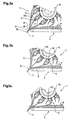
- a section of the transfer area 10 FIG. 1 show in different snapshots Figure 3a-c ,
- the conveyor 1 comprises a plurality of grippers 3 moved along a movement path U.
- the grippers 3 have two gripper jaws 4, 5 which are pivotable relative to one another about a pivot axis extending perpendicular to the plane of the drawing for opening and closing.
- the individual opening of the gripper 3 is accomplished with a gate control, not shown here.
- a gripper is opened in each case at the point of closest approach 10 'of the movement path U to the belt conveyor 2.
- the gripper 3 and the two gripper jaws 4, 5 are also in order a perpendicular to the plane of the drawing pivoting axis.
- the orientation of the gripper 3 and in particular the direction A of the gripper jaw relative to the movement path U or relative to the gripper body 3a individually depending on the position of the gripper 3 within the movement path U can be changed.
- suitable grippers are in the EP-A 0 600 183 described.
- the pivoting movement relative to the movement path or the gripper body 3a is realized by means of a gate control, not shown here.
- the movement path U comprises two vertically extending sections U1, U2, between which the curved transfer area 10 is located.
- the transfer region 10 can be approximately the semicircular region of the movement path U.
- the grippers 3 are oriented in such a way that their gripper jaws, which are limited by the two gripper jaws 4, 5, point in a direction A which is inclined at approximately 45 ° from the vertical.
- the first section U1 hold the gripper 3 products 6. These bend due to gravity down so that they occupy a substantially vertical position over a large part of their length.
- the gripper orientation is changed so that the unstressed edge 6b is further conveyed at the same or preferably a lower line speed as the gripped edge 6a of the product.
- the Curvature of the transfer region 10 is therefore compensated by the change in the orientation of the gripper 3.
- the conveyor 1 can therefore be carried out very space-saving with a strong curvature in the transfer area and therefore in the conveying direction. For example, it is curved so that in the transfer area 10 3 to 5 grippers find space next to each other.
- the product 6 is placed in a lying position in which the unaffected edge 6b in the direction of movement along the trajectory when depositing from a hanging position in which the unaffected edge 6b is arranged in the direction of movement along the movement path U in front of the gripped edge U or in the conveying direction F of the belt conveyor 2 behind the gripped edge 6a.
- the assumed in the transfer area 10 orientation relative to the path of movement U keep the gripper 3 even after opening in the vertically upwardly extending second portion U2 of the path of movement U at.
- a change in the alignment need only be made before or after receiving a new product at a takeover point, not shown here.
- the unattached end 6b of a product first approaches the plane defined by the conveyor belt 2a. It is advantageous if, as shown here, the conveyor belt is arranged so that the unattacked end 6b can cross the plane of the conveyor belt 2a, preferably in which the beginning 2b of the belt conveyor 2 lies in the transfer area 10.
- the conveyor belt 2a at its beginning 2b a support member 7 in the form of an obliquely downwardly bent Guide element on which the unattacked end 6b comes to rest when lowering and from which it is withdrawn on further conveying.
- the support member 7 has the advantage that the free end 6b is given a preferred direction. It is prevented that the end 6b is already conveyed away with the conveyor belt 2a before the gripped end 6a of the product 6 is deposited thereon.
- the grippers 3 are moved in space in such a way that the gripped product is largely straight or only slightly curved until it is deposited. It is therefore also of advantage if the gripper jaw 4 facing the belt conveyor 2 is aligned substantially parallel to the plane of the deposited products 6 when the product 6 is deposited.
- the gripper 3 of the conveyor 1 off FIG. 2 are moved, as already described. The fact that they grip and hand over three products 6 has no influence on the movement process.
Claims (8)
- Procédé pour transporter des produits plats et flexibles (6), notamment des produits d'imprimerie, dans lequel les produits (6) sont transportés jusqu'à une région de transfert (10) au moyen d'un dispositif de transport (1), qui comprend des dispositifs de préhension (3) avec au moins deux mâchoires de préhension (4, 5), lesquels sont déplacés le long d'une trajectoire de déplacement (U), détectent au moins un produit (6) dans la région d'une arête (6a), et peuvent être commandés séparément pour s'ouvrir et se fermer, les produits (6) étant déposés en se chevauchant au moins partiellement dans la région de transfert (10) sur une bande transporteuse (2a) d'un convoyeur à bande (2) s'étendant dans la direction de transport (F) et disposée essentiellement horizontalement, et étant emportés avec elle, les produits étant transportés en position suspendue le long de la trajectoire de déplacement (U) courbe dans la région de transfert (10) et se rapprochant de la bande transporteuse (2a) dans la direction verticale,
caractérisé en ce que
les dispositifs de préhension sont pivotés dans la région de transfert (10) avant la dépose des produits sur la bande transporteuse (2a) au moyen d'une commande à coulisse depuis une position orientée dans sa direction périphérique dans une position orientée à l'opposé de sa direction périphérique, de telle sorte que l'arête (6b) non saisie du produit (6) se déplace avec la même vitesse de bande ou une vitesse de bande inférieure à l'arête saisie (6a). - Procédé selon la revendication 1, caractérisé en ce que l'orientation (A) des dispositifs de préhension (3) peut être modifiée par rapport à la trajectoire de déplacement (U), l'orientation (A) des dispositifs de préhension (3) dans la région de transfert (10) étant modifiée de telle sorte que le produit saisi (6) soit déplacé d'une première position dans laquelle l'arête non saisie (6d) est disposée dans la direction de déplacement avant l'arête saisie (6a), dans une deuxième position dans laquelle l'arête non saisie (6b) est disposée dans la direction de déplacement derrière l'arête saisie (6a).
- Procédé selon la revendication 2, caractérisé en ce que les dispositifs de préhension (3) sont déplacés de telle sorte que l'arête non saisie (6b) d'un produit (6) vient s'appliquer sur un élément de support (7) disposé au début (2b) de la région de transfert (10) et y reste ou n'est déplacée que légèrement pendant au moins une partie du déplacement d'avance des dispositifs de préhension (3) le long de la trajectoire de déplacement (U) dans la région de transfert (10).
- Procédé selon l'une quelconque des revendications précédentes, caractérisé en ce que les dispositifs de préhension (3) sont déplacés de telle sorte que la mâchoire de préhension (4) tournée vers le convoyeur à bande (2) est orientée essentiellement parallèlement au plan des produits déposés (6) lors de la dépose du produit (6).
- Procédé selon l'une quelconque des revendications précédentes, caractérisé en ce que la trajectoire de déplacement (U) s'étend dans une première portion partielle (U1) disposée en amont de la région de transfert (10) et dans une deuxième portion partielle (U2) disposée en aval de la région de transfert (10) essentiellement perpendiculairement à la direction de transport (F).
- Dispositif pour mettre en oeuvre le procédé selon l'une quelconque des revendications précédentes, comprenant un dispositif de transport (1) pour transporter des produits (6) vers une région de transfert (10), qui comprend des dispositifs de préhension (3) avec au moins deux mâchoires de préhension (4, 5), lesquels sont déplacés le long d'une trajectoire de déplacement (U), détectent au moins un produit (6) dans la région d'une arête (6a) et peuvent être commandés séparément pour s'ouvrir et se fermer et comprenant un convoyeur à bande pour évacuer les produits (6) hors de la région de transfert (10) avec une bande transporteuse (2a) disposée essentiellement horizontalement, s'étendant dans la direction de transport (F), la trajectoire de déplacement (U) étant courbée dans la région de transfert (10) et étant réalisée de manière à se rapprocher de la bande transporteuse (2a) dans la direction verticale, les dispositifs de préhension (3) adoptant, en amont de la région de transfert (10) une position dans laquelle ils sont en mesure de transporter les produits (6) de manière suspendue, caractérisé en ce qu'il est prévu une commande à coulisse au moyen de laquelle les dispositifs de préhension peuvent être pivotés d'une position orientée dans sa direction périphérique dans une position orientée à l'opposé de sa direction périphérique, de telle sorte que l'arête non saisie (6b) du produit (6) se déplace dans la région de transfert (10) avec la même vitesse de bande ou une vitesse de bande inférieure à l'arête saisie (6a).
- Dispositif selon la revendication 6, caractérisé en ce que la trajectoire de déplacement (U) s'étend dans une première portion partielle (U1) disposée en amont de la région de transfert (10) et dans une deuxième portion partielle (U2) disposée en aval de la région de transfert (10) essentiellement perpendiculairement à la direction de transport (F).
- Dispositif selon la revendication 6 ou 7, caractérisé en ce que la trajectoire de déplacement (U) se rapproche par le haut du convoyeur à bande (2a) et a une configuration à courbure convexe par rapport à celui-ci dans la région de transfert (10).
Applications Claiming Priority (2)
| Application Number | Priority Date | Filing Date | Title |
|---|---|---|---|
| CH8482002 | 2002-05-22 | ||
| CH8482002 | 2002-05-22 |
Publications (2)
| Publication Number | Publication Date |
|---|---|
| EP1364899A1 EP1364899A1 (fr) | 2003-11-26 |
| EP1364899B1 true EP1364899B1 (fr) | 2008-08-27 |
Family
ID=29275996
Family Applications (1)
| Application Number | Title | Priority Date | Filing Date |
|---|---|---|---|
| EP03003301A Expired - Lifetime EP1364899B1 (fr) | 2002-05-22 | 2003-02-13 | Méthode pour transporter des produits plats et flexibles, et dispositif pour mettre en oeuvre la méthode |
Country Status (6)
| Country | Link |
|---|---|
| US (1) | US7316392B2 (fr) |
| EP (1) | EP1364899B1 (fr) |
| AT (1) | ATE406334T1 (fr) |
| CA (1) | CA2429323C (fr) |
| DE (1) | DE50310398D1 (fr) |
| DK (1) | DK1364899T3 (fr) |
Families Citing this family (7)
| Publication number | Priority date | Publication date | Assignee | Title |
|---|---|---|---|---|
| DE10128833B4 (de) * | 2001-06-15 | 2006-11-02 | Koenig & Bauer Ag | Qualitätskontrollvorrichtung |
| DE50300830D1 (de) * | 2002-03-01 | 2005-09-01 | Ferag Ag | Verfahren und Vorrichtung zur Wandlung eines Stromes gehalten geförderter, flacher Gegenstände in einen Schuppenstrom mit wählbarer Anordnung der Gegenstände |
| CA2468357A1 (fr) * | 2004-04-02 | 2005-10-02 | Dominique Feuiltault | Systeme, dispositif et methode d'alimentation en articles plats |
| FR2890333B1 (fr) * | 2005-09-07 | 2009-01-23 | Mag Systemes Soc Par Actions S | Dispositif d'alimentation automatique des enveloppes destinees a un atelier de mise sous pli de documents |
| EP1834913A1 (fr) * | 2006-03-17 | 2007-09-19 | Ferag AG | Dispositif pour ramasser et convoyer des produits plats |
| US7527261B2 (en) * | 2006-07-13 | 2009-05-05 | Lockheed Martin Corporation | Mailpiece container for stacking mixed mail and method for stacking mail therein |
| US7694949B2 (en) * | 2006-09-18 | 2010-04-13 | Goss International Americas, Inc | Custodial lapped stream mechanism |
Citations (1)
| Publication number | Priority date | Publication date | Assignee | Title |
|---|---|---|---|---|
| EP1340704A2 (fr) * | 2002-03-01 | 2003-09-03 | Ferag AG | Procédé et dispositif pour changer un courant d'articles plats convoyés à l'état maintenu, en un courant imbriqué avec arrangement sélectionnable des articles |
Family Cites Families (10)
| Publication number | Priority date | Publication date | Assignee | Title |
|---|---|---|---|---|
| CH629160A5 (en) * | 1978-04-11 | 1982-04-15 | Ferag Ag | Device for subdividing a continuous stream, in particular an overlapping stream, of flat products into individual groups |
| CH660170A5 (de) * | 1983-05-31 | 1987-03-31 | Ferag Ag | Einrichtung zum zwischenspeichern von druckprodukten. |
| JP2918725B2 (ja) * | 1991-10-09 | 1999-07-12 | 株式会社金田機械製作所 | キャリア用脱荷搬出装置 |
| DE59302448D1 (de) * | 1993-01-14 | 1996-06-05 | Ferag Ag | Vorrichtung zum Transportieren von flächigen Erzeugnissen |
| EP0675062B1 (fr) * | 1994-03-24 | 1997-12-17 | Ferag AG | Dispositif pour l'alimentation d'articles plats à un dispositif de traitement de produits imprimés |
| SE502958C2 (sv) * | 1994-08-19 | 1996-02-26 | Sten Wallsten Ind Ab | Anordning för avlämnande av utvalda exemplar av föremål från en transportbana |
| JP3793232B2 (ja) * | 1995-04-11 | 2006-07-05 | グラファ−ホルディング・アクチェンゲゼルシャフト | 印刷物ストリームの搬送方法及び装置 |
| CA2187000C (fr) | 1995-10-03 | 2005-05-03 | Walter Reist | Pince pour articles en feuilles |
| DE59603772D1 (de) * | 1995-10-03 | 2000-01-05 | Ferag Ag | Klammer für flächige Gegenstände |
| DK1193201T3 (da) * | 2000-10-02 | 2004-03-08 | Ferag Ag | Fremgangsmåde og anordning til dannelse af en dobbeltskelformation af trykkeriprodukter |
-
2003
- 2003-02-13 DE DE50310398T patent/DE50310398D1/de not_active Expired - Lifetime
- 2003-02-13 EP EP03003301A patent/EP1364899B1/fr not_active Expired - Lifetime
- 2003-02-13 DK DK03003301T patent/DK1364899T3/da active
- 2003-02-13 AT AT03003301T patent/ATE406334T1/de active
- 2003-05-13 US US10/436,573 patent/US7316392B2/en not_active Expired - Fee Related
- 2003-05-21 CA CA2429323A patent/CA2429323C/fr not_active Expired - Fee Related
Patent Citations (1)
| Publication number | Priority date | Publication date | Assignee | Title |
|---|---|---|---|---|
| EP1340704A2 (fr) * | 2002-03-01 | 2003-09-03 | Ferag AG | Procédé et dispositif pour changer un courant d'articles plats convoyés à l'état maintenu, en un courant imbriqué avec arrangement sélectionnable des articles |
Also Published As
| Publication number | Publication date |
|---|---|
| DK1364899T3 (da) | 2008-12-01 |
| EP1364899A1 (fr) | 2003-11-26 |
| ATE406334T1 (de) | 2008-09-15 |
| US7316392B2 (en) | 2008-01-08 |
| US20030218297A1 (en) | 2003-11-27 |
| CA2429323C (fr) | 2011-10-04 |
| CA2429323A1 (fr) | 2003-11-22 |
| DE50310398D1 (de) | 2008-10-09 |
| AU2003203609A1 (en) | 2003-12-11 |
Similar Documents
| Publication | Publication Date | Title |
|---|---|---|
| EP0557680B1 (fr) | Pince pour transporteur pour transporter des produits imprimés à une ou plusieurs feuilles | |
| EP0330868A1 (fr) | Procédé et dispositif d'évacuation de produits imprimés, qui sont amenés en formation en écailles | |
| DE19906202A1 (de) | Vorrichtung zum Verarbeiten von flexiblen, flächigen Erzeugnissen | |
| DE3306815C2 (de) | Vorrichtung zum transportieren von in einer schuppenformation anfallenden flaechigen erzeugnissen, insbesondere druckprodukten | |
| EP0564812B1 (fr) | Procédé et dispositif pour ouvrir des produits d'imprimerie pliés | |
| DE3633617C2 (de) | Vorrichtung und Verfahren zum Einlegen von Druckprodukten in eine Trommel | |
| EP1364899B1 (fr) | Méthode pour transporter des produits plats et flexibles, et dispositif pour mettre en oeuvre la méthode | |
| EP0854105B1 (fr) | Méthode et dispositif pour traiter des produits imprimes plats, comme des journaux, des magazines, et des parties de cela | |
| EP1281650B1 (fr) | Méthode et dispositif pour le regroupement et le transport ultérieur d'articles plats | |
| DE19916668A1 (de) | Vorrichtung zum Transportieren von flach liegenden Zuschnitten | |
| EP0754642A2 (fr) | Dispositif de sortie de produits en forme de feuille | |
| DE19621331B4 (de) | Vorrichtung zur Aufteilung eines Produktstroms | |
| EP0557679B1 (fr) | Pince pour transporter des produits imprimés à une ou plusieurs feuilles | |
| EP0218804B1 (fr) | Dispositif pour reprendre et transférer des feuilles pliées d'un dispositif de transport | |
| EP2008522A1 (fr) | Procédé et dispositif destinés à la saisie de portions à boucles | |
| EP1547950B1 (fr) | Méthode et dispositif pour stabiliser et positionner des objets plats | |
| EP0863099B1 (fr) | Dispositif pour séparer des produits imprimés empilés | |
| EP1253098A1 (fr) | Appareil pour la manutention des produits imprimés alimentés vers un dispositif d'empilage | |
| DE3837222A1 (de) | Verfahren und vorrichtung zum verpackungsgerechten gruppenweisen aneinanderruecken von wuersten | |
| EP0518064A1 (fr) | Procédé et appareil pour la manutention de produits imprimés | |
| DE3908347C2 (fr) | ||
| EP2367745B1 (fr) | Dispositif et procédé de transfert d'objets plats flexibles | |
| EP0767125B1 (fr) | Pince pour des articles plats | |
| WO1999055609A1 (fr) | Procede et dispositif pour poursuivre l'acheminement d'objets plats arrivant dans un courant lamellaire | |
| CH574364A5 (en) | Transfer conveyor for folded newspapers - has scissor type pick up heads on overhead chain track |
Legal Events
| Date | Code | Title | Description |
|---|---|---|---|
| PUAI | Public reference made under article 153(3) epc to a published international application that has entered the european phase |
Free format text: ORIGINAL CODE: 0009012 |
|
| AK | Designated contracting states |
Kind code of ref document: A1 Designated state(s): AT BE BG CH CY CZ DE DK EE ES FI FR GB GR HU IE IT LI LU MC NL PT SE SI SK TR |
|
| AX | Request for extension of the european patent |
Extension state: AL LT LV MK RO |
|
| 17P | Request for examination filed |
Effective date: 20040116 |
|
| AKX | Designation fees paid |
Designated state(s): AT BE BG CH CY CZ DE DK EE ES FI FR GB GR HU IE IT LI LU MC NL PT SE SI SK TR |
|
| GRAP | Despatch of communication of intention to grant a patent |
Free format text: ORIGINAL CODE: EPIDOSNIGR1 |
|
| GRAS | Grant fee paid |
Free format text: ORIGINAL CODE: EPIDOSNIGR3 |
|
| GRAA | (expected) grant |
Free format text: ORIGINAL CODE: 0009210 |
|
| AK | Designated contracting states |
Kind code of ref document: B1 Designated state(s): AT BE BG CH CY CZ DE DK EE ES FI FR GB GR HU IE IT LI LU MC NL PT SE SI SK TR |
|
| REG | Reference to a national code |
Ref country code: GB Ref legal event code: FG4D Free format text: NOT ENGLISH |
|
| REG | Reference to a national code |
Ref country code: CH Ref legal event code: NV Representative=s name: PATENTANWAELTE SCHAAD, BALASS, MENZL & PARTNER AG Ref country code: CH Ref legal event code: EP |
|
| REG | Reference to a national code |
Ref country code: IE Ref legal event code: FG4D Free format text: LANGUAGE OF EP DOCUMENT: GERMAN |
|
| REF | Corresponds to: |
Ref document number: 50310398 Country of ref document: DE Date of ref document: 20081009 Kind code of ref document: P |
|
| REG | Reference to a national code |
Ref country code: SE Ref legal event code: TRGR |
|
| REG | Reference to a national code |
Ref country code: DK Ref legal event code: T3 |
|
| PG25 | Lapsed in a contracting state [announced via postgrant information from national office to epo] |
Ref country code: ES Free format text: LAPSE BECAUSE OF FAILURE TO SUBMIT A TRANSLATION OF THE DESCRIPTION OR TO PAY THE FEE WITHIN THE PRESCRIBED TIME-LIMIT Effective date: 20081208 Ref country code: NL Free format text: LAPSE BECAUSE OF FAILURE TO SUBMIT A TRANSLATION OF THE DESCRIPTION OR TO PAY THE FEE WITHIN THE PRESCRIBED TIME-LIMIT Effective date: 20080827 |
|
| PG25 | Lapsed in a contracting state [announced via postgrant information from national office to epo] |
Ref country code: FI Free format text: LAPSE BECAUSE OF FAILURE TO SUBMIT A TRANSLATION OF THE DESCRIPTION OR TO PAY THE FEE WITHIN THE PRESCRIBED TIME-LIMIT Effective date: 20080827 Ref country code: SI Free format text: LAPSE BECAUSE OF FAILURE TO SUBMIT A TRANSLATION OF THE DESCRIPTION OR TO PAY THE FEE WITHIN THE PRESCRIBED TIME-LIMIT Effective date: 20080827 |
|
| REG | Reference to a national code |
Ref country code: IE Ref legal event code: FD4D |
|
| PG25 | Lapsed in a contracting state [announced via postgrant information from national office to epo] |
Ref country code: IE Free format text: LAPSE BECAUSE OF FAILURE TO SUBMIT A TRANSLATION OF THE DESCRIPTION OR TO PAY THE FEE WITHIN THE PRESCRIBED TIME-LIMIT Effective date: 20080827 Ref country code: BG Free format text: LAPSE BECAUSE OF FAILURE TO SUBMIT A TRANSLATION OF THE DESCRIPTION OR TO PAY THE FEE WITHIN THE PRESCRIBED TIME-LIMIT Effective date: 20081127 |
|
| PG25 | Lapsed in a contracting state [announced via postgrant information from national office to epo] |
Ref country code: SK Free format text: LAPSE BECAUSE OF FAILURE TO SUBMIT A TRANSLATION OF THE DESCRIPTION OR TO PAY THE FEE WITHIN THE PRESCRIBED TIME-LIMIT Effective date: 20080827 Ref country code: CZ Free format text: LAPSE BECAUSE OF FAILURE TO SUBMIT A TRANSLATION OF THE DESCRIPTION OR TO PAY THE FEE WITHIN THE PRESCRIBED TIME-LIMIT Effective date: 20080827 Ref country code: PT Free format text: LAPSE BECAUSE OF FAILURE TO SUBMIT A TRANSLATION OF THE DESCRIPTION OR TO PAY THE FEE WITHIN THE PRESCRIBED TIME-LIMIT Effective date: 20090127 |
|
| PLBE | No opposition filed within time limit |
Free format text: ORIGINAL CODE: 0009261 |
|
| STAA | Information on the status of an ep patent application or granted ep patent |
Free format text: STATUS: NO OPPOSITION FILED WITHIN TIME LIMIT |
|
| PG25 | Lapsed in a contracting state [announced via postgrant information from national office to epo] |
Ref country code: EE Free format text: LAPSE BECAUSE OF FAILURE TO SUBMIT A TRANSLATION OF THE DESCRIPTION OR TO PAY THE FEE WITHIN THE PRESCRIBED TIME-LIMIT Effective date: 20080827 |
|
| 26N | No opposition filed |
Effective date: 20090528 |
|
| BERE | Be: lapsed |
Owner name: FERAG AG Effective date: 20090228 |
|
| PG25 | Lapsed in a contracting state [announced via postgrant information from national office to epo] |
Ref country code: MC Free format text: LAPSE BECAUSE OF NON-PAYMENT OF DUE FEES Effective date: 20090228 |
|
| REG | Reference to a national code |
Ref country code: FR Ref legal event code: ST Effective date: 20091030 |
|
| PG25 | Lapsed in a contracting state [announced via postgrant information from national office to epo] |
Ref country code: BE Free format text: LAPSE BECAUSE OF NON-PAYMENT OF DUE FEES Effective date: 20090228 |
|
| PG25 | Lapsed in a contracting state [announced via postgrant information from national office to epo] |
Ref country code: FR Free format text: LAPSE BECAUSE OF NON-PAYMENT OF DUE FEES Effective date: 20090302 |
|
| PG25 | Lapsed in a contracting state [announced via postgrant information from national office to epo] |
Ref country code: GR Free format text: LAPSE BECAUSE OF FAILURE TO SUBMIT A TRANSLATION OF THE DESCRIPTION OR TO PAY THE FEE WITHIN THE PRESCRIBED TIME-LIMIT Effective date: 20081128 |
|
| PG25 | Lapsed in a contracting state [announced via postgrant information from national office to epo] |
Ref country code: LU Free format text: LAPSE BECAUSE OF NON-PAYMENT OF DUE FEES Effective date: 20090213 |
|
| PGFP | Annual fee paid to national office [announced via postgrant information from national office to epo] |
Ref country code: DK Payment date: 20110210 Year of fee payment: 9 |
|
| PGFP | Annual fee paid to national office [announced via postgrant information from national office to epo] |
Ref country code: IT Payment date: 20110219 Year of fee payment: 9 Ref country code: CH Payment date: 20110216 Year of fee payment: 9 Ref country code: AT Payment date: 20110214 Year of fee payment: 9 Ref country code: DE Payment date: 20110218 Year of fee payment: 9 Ref country code: SE Payment date: 20110214 Year of fee payment: 9 |
|
| PG25 | Lapsed in a contracting state [announced via postgrant information from national office to epo] |
Ref country code: HU Free format text: LAPSE BECAUSE OF FAILURE TO SUBMIT A TRANSLATION OF THE DESCRIPTION OR TO PAY THE FEE WITHIN THE PRESCRIBED TIME-LIMIT Effective date: 20090228 |
|
| PGFP | Annual fee paid to national office [announced via postgrant information from national office to epo] |
Ref country code: GB Payment date: 20110217 Year of fee payment: 9 |
|
| PG25 | Lapsed in a contracting state [announced via postgrant information from national office to epo] |
Ref country code: TR Free format text: LAPSE BECAUSE OF FAILURE TO SUBMIT A TRANSLATION OF THE DESCRIPTION OR TO PAY THE FEE WITHIN THE PRESCRIBED TIME-LIMIT Effective date: 20080827 |
|
| PG25 | Lapsed in a contracting state [announced via postgrant information from national office to epo] |
Ref country code: CY Free format text: LAPSE BECAUSE OF FAILURE TO SUBMIT A TRANSLATION OF THE DESCRIPTION OR TO PAY THE FEE WITHIN THE PRESCRIBED TIME-LIMIT Effective date: 20080827 |
|
| REG | Reference to a national code |
Ref country code: CH Ref legal event code: PL |
|
| GBPC | Gb: european patent ceased through non-payment of renewal fee |
Effective date: 20120213 |
|
| PG25 | Lapsed in a contracting state [announced via postgrant information from national office to epo] |
Ref country code: LI Free format text: LAPSE BECAUSE OF NON-PAYMENT OF DUE FEES Effective date: 20120229 Ref country code: CH Free format text: LAPSE BECAUSE OF NON-PAYMENT OF DUE FEES Effective date: 20120229 Ref country code: SE Free format text: LAPSE BECAUSE OF NON-PAYMENT OF DUE FEES Effective date: 20120214 |
|
| REG | Reference to a national code |
Ref country code: DK Ref legal event code: EBP |
|
| PG25 | Lapsed in a contracting state [announced via postgrant information from national office to epo] |
Ref country code: IT Free format text: LAPSE BECAUSE OF NON-PAYMENT OF DUE FEES Effective date: 20120213 |
|
| REG | Reference to a national code |
Ref country code: DE Ref legal event code: R119 Ref document number: 50310398 Country of ref document: DE Effective date: 20120901 |
|
| REG | Reference to a national code |
Ref country code: AT Ref legal event code: MM01 Ref document number: 406334 Country of ref document: AT Kind code of ref document: T Effective date: 20120213 |
|
| PG25 | Lapsed in a contracting state [announced via postgrant information from national office to epo] |
Ref country code: GB Free format text: LAPSE BECAUSE OF NON-PAYMENT OF DUE FEES Effective date: 20120213 Ref country code: AT Free format text: LAPSE BECAUSE OF NON-PAYMENT OF DUE FEES Effective date: 20120213 |
|
| PG25 | Lapsed in a contracting state [announced via postgrant information from national office to epo] |
Ref country code: DE Free format text: LAPSE BECAUSE OF NON-PAYMENT OF DUE FEES Effective date: 20120901 |
|
| PG25 | Lapsed in a contracting state [announced via postgrant information from national office to epo] |
Ref country code: DK Free format text: LAPSE BECAUSE OF NON-PAYMENT OF DUE FEES Effective date: 20120229 |