EP1364607A1 - Schwammhalter - Google Patents
Schwammhalter Download PDFInfo
- Publication number
- EP1364607A1 EP1364607A1 EP03003473A EP03003473A EP1364607A1 EP 1364607 A1 EP1364607 A1 EP 1364607A1 EP 03003473 A EP03003473 A EP 03003473A EP 03003473 A EP03003473 A EP 03003473A EP 1364607 A1 EP1364607 A1 EP 1364607A1
- Authority
- EP
- European Patent Office
- Prior art keywords
- sponge
- holder
- sponge holder
- holder according
- wall
- Prior art date
- Legal status (The legal status is an assumption and is not a legal conclusion. Google has not performed a legal analysis and makes no representation as to the accuracy of the status listed.)
- Granted
Links
Images



Classifications
-
- A—HUMAN NECESSITIES
- A47—FURNITURE; DOMESTIC ARTICLES OR APPLIANCES; COFFEE MILLS; SPICE MILLS; SUCTION CLEANERS IN GENERAL
- A47J—KITCHEN EQUIPMENT; COFFEE MILLS; SPICE MILLS; APPARATUS FOR MAKING BEVERAGES
- A47J43/00—Implements for preparing or holding food, not provided for in other groups of this subclass
- A47J43/28—Other culinary hand implements, e.g. spatulas, pincers, forks or like food holders, ladles, skimming ladles, cooking spoons; Spoon-holders attached to cooking pots
- A47J43/283—Tongs; Devices for picking, holding or rotating food
-
- A—HUMAN NECESSITIES
- A47—FURNITURE; DOMESTIC ARTICLES OR APPLIANCES; COFFEE MILLS; SPICE MILLS; SUCTION CLEANERS IN GENERAL
- A47J—KITCHEN EQUIPMENT; COFFEE MILLS; SPICE MILLS; APPARATUS FOR MAKING BEVERAGES
- A47J43/00—Implements for preparing or holding food, not provided for in other groups of this subclass
- A47J43/24—Devices for washing vegetables or the like
-
- A—HUMAN NECESSITIES
- A47—FURNITURE; DOMESTIC ARTICLES OR APPLIANCES; COFFEE MILLS; SPICE MILLS; SUCTION CLEANERS IN GENERAL
- A47K—SANITARY EQUIPMENT; ACCESSORIES THEREFOR, e.g. TOILET ACCESSORIES
- A47K7/00—Body washing or cleaning implements
- A47K7/02—Bathing sponges, brushes, gloves or similar cleaning or rubbing implements
-
- A—HUMAN NECESSITIES
- A47—FURNITURE; DOMESTIC ARTICLES OR APPLIANCES; COFFEE MILLS; SPICE MILLS; SUCTION CLEANERS IN GENERAL
- A47K—SANITARY EQUIPMENT; ACCESSORIES THEREFOR, e.g. TOILET ACCESSORIES
- A47K2201/00—Details of connections of bathroom accessories, e.g. fixing soap or towel holder to a wall
Definitions
- the invention relates to a device for releasably holding sponges out of use, both in the home and in business.
- Such sponges are usually used in the wet, at least still damp on a work surface or in placed in a bowl.
- the major disadvantage is that the Did not or only insufficiently swam in the area of its contact surface Atmosphere is accessible and therefore not in this area, at least but can only dry much more slowly than in its atmosphere immediately exposed areas.
- this is the case especially in this part of the deposited sponges for germination or Spore formation, which also affect adjacent areas of the sponge can. This is especially dangerous if the sponge is like it is often the case, is not or insufficiently expressed by the user of use is discarded.
- the space required for storage the sponge on the work table or other work surface or the installation of the sponge bowl is required for storage the sponge on the work table or other work surface or the installation of the sponge bowl.
- the object of the present invention is therefore to provide a device for Holding sponges without the aforementioned disadvantages of the known To create sponge trays, covering the surface of the sponge exposed to the atmosphere as much as possible, easily into the device can be used and removed from it, but at the same time reliably is held.
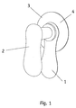
- the sponge holder according to the invention in the embodiment according to FIG. 1 and 2 consists largely of the sponge carrier with the two parallel holding arms (1) and (2) through the Connection piece / the spacer (3) with a defined length rigid are connected. Below the lower arm (1) is in the imaginary Axis of the connecting piece (3) of the suction holder (4) known per se Attach the sponge holder to smooth surfaces such as tiles, Mirrors, glass and metal surfaces attached.
- the sponge to be picked up by the sponge holder is between the Holding arms (1) and (2) pushed by slightly pressing them together.
- the distance between the holding arms (1) and (2) to one another is such that they have a sufficient clamping effect around the respective sponge secure, but easy to remove even when the front open ends of the holding arms preferably from the adhesive surface of the suction holder (4) (tile, mirror, etc.) are directed downwards.
- the Length of the connecting piece (3) and thus the distance between the holding arms (1) and (2) is determined according to the height / thickness of the sponges for which the sponge holder is provided for.
- the holding arms (1) and (2) are designed in their cross section so that the top of the holding arm (1) and bottom of the Holding arms (2) the smallest possible areas of the sponge used cover. As can be seen from Fig. 2, they are in the Embodiment of FIG. 1 designed convex. You can in the sense the invention, however, as can be seen in FIGS. 7 and 8, narrow straight Be support surfaces or circular sections of holding arms with a round Cross-section.
- the holding arms can be directed towards the sponge Pages have a pimpled design or longitudinal or transverse webs for secure Hold the sponge in place.
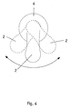
- 3 and 4 is the upper one Holding arm (2) with the connecting piece (3 ') in the lower holding arm (1) one of its longitudinal ends horizontal to the holding arms around the axis of the connecting piece (3 ') pivotally mounted. With that, the onset and / or the removal of the sponge can be facilitated. in the otherwise this embodiment corresponds to that described above 1 and 2.
- FIG. 5 and 6 is another embodiment of the sponge holder shown, in which the upper holding arm (2 ') with the connecting piece (3 ") in the lower holding arm (1 ') at one longitudinal end, preferably by means of a ball joint, rotatable and swiveling in all directions, at least however in the direction away from the holding arm (1) is foldable.
- the sponge carriers (7, 8, 9) or (7 ', 8', 9 ') arranged such that the connecting pieces (9) or (9') run parallel to the adhesive surface of the suction holder (4) and the open end the sponge carrier is directed away from the suction cup.
- the holding arms (7, 8) and (7 ', 8') have in the illustrated embodiments right-angled or circular cross-sections; however, you can also use the Have shape of the holding arms (1) and (2) according to FIGS. 1 to 6.
- FIG. 9 finally shows the sponge holder in the embodiment according to FIG Fig. 5 as an example with an inserted sponge.
- the sponge holder according to the invention makes it possible to Sponge, especially in the moist or wet state after his Use, to be arranged as freely as possible in the room and only one very small part of its surface due to the holding arms of the sponge carrier cover without securely holding the sponge in place affect. This allows the sponge to dry properly as it is largely free in the room. This speeds up drying essential and largely prevents nucleation in the Contrary to the usual placement of the sponge in a bowl or on another area.
- the lower arm of the sponge holder for its part not already on the wall surface or other attachment surface abuts, but is arranged at a distance from this, in particular is determined by the height of the suction cup, the Also did not sponge on the sponge holder according to the invention against the wall, like hanging the sponge for example by means of a cord attached to it or other Hanger happens.
- the sponge is being exploited its elasticity from the holding arms of the sponge carrier is also safe held and easily inserted into and out of the sponge holder removable. 3 and 4 as well 5 and 6 will still insert and remove the sponge additionally relieved.
Landscapes
- Engineering & Computer Science (AREA)
- Mechanical Engineering (AREA)
- Food Science & Technology (AREA)
- Health & Medical Sciences (AREA)
- Public Health (AREA)
- Epidemiology (AREA)
- General Health & Medical Sciences (AREA)
- Hooks, Suction Cups, And Attachment By Adhesive Means (AREA)
- Supports Or Holders For Household Use (AREA)
- Cleaning Implements For Floors, Carpets, Furniture, Walls, And The Like (AREA)
- Electroplating Methods And Accessories (AREA)
- Polishing Bodies And Polishing Tools (AREA)
Abstract
Description
- Fig. 1:
- den erfindungsgemäßen Schwammhalter mit in sich starrem Schwammhalter und angesetztem Saughalter in der Seitenansicht von rechts;
- Fig. 2:
- den Schwammhalter gemäß Fig. 1 in der Ansicht von den vorderen Enden der Haltearme des Schwammträgers her;
- Fig. 3:
- den Schwammhalter gemäß Fig. 1, jedoch mit gegenüber dem unteren Schwammträger seitlich verschwenkbarem oberem Haltearm in der Seitenansicht von rechts;
- Fig. 4:
- den Schwammhalter gemäß Fig. 3 in der Aufsicht von oben mit drei Schwenkstellungen des oberen Haltearms;
- Fig. 5:
- den Schwammhalter mit vom unteren Haltearm hochklappbarem oberem Haltearm in der Seitenansicht von links;
- Fig. 6:
- den Schwammhalter gemäß Fig. 5 mit abgeklapptem und hochgeklappten oberem Haltearm;
- Fig. 7:
- einen Schwammhalter mit von der Haftfläche des Saughalters weg gerichteter Öffnung des Schwammträgers und in ihrem Querschnitt rechtwinkligen Haltearmen, in der Seitenansicht von rechts;
- Fig. 8:
- einen Schwammhalter gemäß Fig. 7 mit im Querschnitt runden Haltearmen;
- Fig. 9:
- den Schwammhalter mit eingesetztem Schwamm.
Claims (9)
- Vorrichtung für die lösbare Halterung von Schwämmen (Schwammhalter), dadurch gekennzeichnet, daß ein unterer Haltearm (1) und ein dazu im Abstand parallel verlaufender Haltearm (2) durch ein Verbindungsstück (3) verbunden sind und den Schwammträger bilden, in den der Schwamm lösbar eingesetzt wird, wobei die Länge des Verbindungsstücks (3) der Höhe/Dicke des Schwamms angepaßt ist, und daß die Haltearme (1, 2) an ihren dem eingesetzten Schwamm zugewandten Seiten so gestaltet sind, daß sie jeweils nur eine kleine Angriffsfläche bezüglich des Schwamms aufweisen, und daß der Schwammhalter in bekannter Weise an einer Wand oder sonstigen Tragefläche angesetzt ist.
- Schwammhalter nach Anspruch 1, dadurch gekennzeichnet, daß der Schwammträger (1, 2, 3) mittels eines Saughalters (4), der auf der Unterseite des Haltearms (1) und vom eingesetzten Schwamm abgewandt angeordnet ist, an der Wand oder sonstigen Befestigungsfläche fest, jedoch lösbar angesetzt wird.
- Schwammhalter nach Anspruch 1 und 2, dadurch gekennzeichnet, daß dieser statt durch den Saughalter (4) mittels eines Schraubzapfens, eines Gewindezapfens oder in sonstiger Weise an der Wand oder sonstigen Befestigungsfläche angebracht wird.
- Schwammhalter nach Anspruch 1 und Anspruch 2 oder Anspruch 3, dadurch gekennzeichnet, daß der obere Haltearm 2 um die Längsachse des Verbindungsstücks (3') und waagerecht zur Befestigungsfläche des Schwammhalters schwenkbar ist.
- Schwammhalter nach Anspruch 1 und Anspruch 2 oder Anspruch 3, dadurch gekennzeichnet, daß der obere Haltearm (2') mit dem Verbindungsstück (3") nach der vom unteren Haltearm (1) und der Befestigungsfläche des Schwammhalters abgewandten Seite hochklappbar ist.
- Schwammhalter nach einem oder mehreren der Ansprüche 1 bis 5, dadurch gekennzeichnet, daß die Haltearme (1, 2; 1', 2'; 7, 8; 7', 8') des Schwammhalters parallel zur Befestigungsfläche (Wand usw.) angeordnet sind.
- Schwammhalter nach einem oder mehreren der Ansprüche 1 bis 5, dadurch gekennzeichnet, daß die Haltearme (1, 2; 1', 2'; 7, 8; 7', 8') des Schwammhalters im rechten Winkel zur Befestigungsfläche (Wand usw.) verlaufen.
- Schwammhalter nach Anspruch 1 oder einem der Ansprüche 4 bis 7, dadurch gekennzeichnet, daß die Haltearme (1, 2; 1', 2'; 7, 8; 7', 8') ovalen, rechteckigen, kreisrunden, drei- oder mehreckigen Querschnitt haben.
- Schwammhalter nach Anspruch 8, dadurch gekennzeichnet, daß die Haltearme (1, 2; 1', 2'; 7, 8; 7', 8') auf ihren dem Schwamm zu gerichteten Seiten noppenartig gestaltet sind oder Längs- und/oder Querstege haben.
Applications Claiming Priority (2)
| Application Number | Priority Date | Filing Date | Title |
|---|---|---|---|
| DE20202905U | 2002-02-25 | ||
| DE20202905U DE20202905U1 (de) | 2002-02-25 | 2002-02-25 | Schwammhalter |
Publications (2)
| Publication Number | Publication Date |
|---|---|
| EP1364607A1 true EP1364607A1 (de) | 2003-11-26 |
| EP1364607B1 EP1364607B1 (de) | 2006-09-27 |
Family
ID=7968225
Family Applications (1)
| Application Number | Title | Priority Date | Filing Date |
|---|---|---|---|
| EP03003473A Expired - Lifetime EP1364607B1 (de) | 2002-02-25 | 2003-02-15 | Schwammhalter |
Country Status (3)
| Country | Link |
|---|---|
| EP (1) | EP1364607B1 (de) |
| AT (1) | ATE340528T1 (de) |
| DE (2) | DE20202905U1 (de) |
Citations (2)
| Publication number | Priority date | Publication date | Assignee | Title |
|---|---|---|---|---|
| US5277389A (en) * | 1992-03-23 | 1994-01-11 | Ballares Virgo V | No hands shower back scrubber |
| FR2763495A3 (fr) * | 1997-05-23 | 1998-11-27 | Roland Francois Ferdin Simeoni | Frotte-dos de toilette fixe sans intervention manuelle |
-
2002
- 2002-02-25 DE DE20202905U patent/DE20202905U1/de not_active Expired - Lifetime
-
2003
- 2003-02-15 DE DE50305151T patent/DE50305151D1/de not_active Expired - Fee Related
- 2003-02-15 EP EP03003473A patent/EP1364607B1/de not_active Expired - Lifetime
- 2003-02-15 AT AT03003473T patent/ATE340528T1/de not_active IP Right Cessation
Patent Citations (2)
| Publication number | Priority date | Publication date | Assignee | Title |
|---|---|---|---|---|
| US5277389A (en) * | 1992-03-23 | 1994-01-11 | Ballares Virgo V | No hands shower back scrubber |
| FR2763495A3 (fr) * | 1997-05-23 | 1998-11-27 | Roland Francois Ferdin Simeoni | Frotte-dos de toilette fixe sans intervention manuelle |
Also Published As
| Publication number | Publication date |
|---|---|
| DE50305151D1 (de) | 2006-11-09 |
| ATE340528T1 (de) | 2006-10-15 |
| EP1364607B1 (de) | 2006-09-27 |
| DE20202905U1 (de) | 2002-07-25 |
Similar Documents
| Publication | Publication Date | Title |
|---|---|---|
| EP0757903B1 (de) | Mophalter sowie Mopbezug hierfür | |
| DE60208379T2 (de) | Haltevorrichtung | |
| WO2007101776A2 (de) | Regalbodenträger mit distanzelementen | |
| EP1364607A1 (de) | Schwammhalter | |
| DE20003623U1 (de) | Hängeanordnung zum Halten von Toilettenartikeln | |
| DE3024414A1 (de) | Aufhaengevorrichtung fuer mit einem stiel versehene arbeitsgeraetschaften | |
| DE3327565A1 (de) | Aufstellbarer insektenfaenger | |
| EP0306555B1 (de) | Eimer, insbesondere zum Tränken von Tieren | |
| DE29821437U1 (de) | Blumenkastenhalter | |
| EP1241969B1 (de) | Haltevorrichtung für handtücher | |
| DE2854176C2 (de) | Kleidungs- und Wäschehalter für eine Duschtrennwand | |
| DE202011003251U1 (de) | Vorrichtung zur Halterung von Gegenständen an einem Balkongeländer | |
| DE2750749A1 (de) | Standascher | |
| DE4028532C2 (de) | ||
| DE10004126B4 (de) | Vorrichtung zum Aufhängen von Gegenständen an insbesondere durch Paneele oder Profilhölzer verkleideten Wänden oder Decken | |
| DE19832171C1 (de) | Sportgerätehalter | |
| DE3942523C2 (de) | ||
| DD255074A1 (de) | Kippvorrichtung fuer magazinbeuten | |
| DE8809496U1 (de) | Einbaugehäuse mit eingesteckter Leiterplatte | |
| DE19807724A1 (de) | Zweiteiliges Wandskihalterungssystem | |
| DE10322175B4 (de) | Vorrichtung zum Verbinden von Reinigungsgeräten mit einem Stiel | |
| DE20001637U1 (de) | Vorrichtung zum Aufhängen von Gegenständen an, insbesondere durch Panele oder Profilhölzer verkleideten Wänden oder Decken | |
| DE1288853B (de) | Halteklammer | |
| DE1750716C (de) | Vorrichtung zum Aufhängen von Gegenständen, insbesondere Rohren und dgl., mit begrenzter Bewegungsfreiheit. Ausscheidung aus: 1303082 | |
| DE8310486U1 (de) | An einer wand zu befestigender einrichtungsgegenstand, insbesondere sanitaergegenstand |
Legal Events
| Date | Code | Title | Description |
|---|---|---|---|
| PUAI | Public reference made under article 153(3) epc to a published international application that has entered the european phase |
Free format text: ORIGINAL CODE: 0009012 |
|
| AK | Designated contracting states |
Kind code of ref document: A1 Designated state(s): AT BE BG CH CY CZ DE DK EE ES FI FR GB GR HU IE IT LI LU MC NL PT SE SI SK TR |
|
| AX | Request for extension of the european patent |
Extension state: AL LT LV MK RO |
|
| 17P | Request for examination filed |
Effective date: 20040526 |
|
| AKX | Designation fees paid |
Designated state(s): AT BE BG CH CY CZ DE DK EE ES FI FR GB GR HU IE IT LI LU MC NL PT SE SI SK TR |
|
| GRAP | Despatch of communication of intention to grant a patent |
Free format text: ORIGINAL CODE: EPIDOSNIGR1 |
|
| GRAS | Grant fee paid |
Free format text: ORIGINAL CODE: EPIDOSNIGR3 |
|
| GRAA | (expected) grant |
Free format text: ORIGINAL CODE: 0009210 |
|
| AK | Designated contracting states |
Kind code of ref document: B1 Designated state(s): AT BE BG CH CY CZ DE DK EE ES FI FR GB GR HU IE IT LI LU MC NL PT SE SI SK TR |
|
| PG25 | Lapsed in a contracting state [announced via postgrant information from national office to epo] |
Ref country code: IT Free format text: LAPSE BECAUSE OF FAILURE TO SUBMIT A TRANSLATION OF THE DESCRIPTION OR TO PAY THE FEE WITHIN THE PRESCRIBED TIME-LIMIT;WARNING: LAPSES OF ITALIAN PATENTS WITH EFFECTIVE DATE BEFORE 2007 MAY HAVE OCCURRED AT ANY TIME BEFORE 2007. THE CORRECT EFFECTIVE DATE MAY BE DIFFERENT FROM THE ONE RECORDED. Effective date: 20060927 Ref country code: SI Free format text: LAPSE BECAUSE OF FAILURE TO SUBMIT A TRANSLATION OF THE DESCRIPTION OR TO PAY THE FEE WITHIN THE PRESCRIBED TIME-LIMIT Effective date: 20060927 Ref country code: SK Free format text: LAPSE BECAUSE OF FAILURE TO SUBMIT A TRANSLATION OF THE DESCRIPTION OR TO PAY THE FEE WITHIN THE PRESCRIBED TIME-LIMIT Effective date: 20060927 Ref country code: NL Free format text: LAPSE BECAUSE OF FAILURE TO SUBMIT A TRANSLATION OF THE DESCRIPTION OR TO PAY THE FEE WITHIN THE PRESCRIBED TIME-LIMIT Effective date: 20060927 Ref country code: IE Free format text: LAPSE BECAUSE OF FAILURE TO SUBMIT A TRANSLATION OF THE DESCRIPTION OR TO PAY THE FEE WITHIN THE PRESCRIBED TIME-LIMIT Effective date: 20060927 Ref country code: CZ Free format text: LAPSE BECAUSE OF FAILURE TO SUBMIT A TRANSLATION OF THE DESCRIPTION OR TO PAY THE FEE WITHIN THE PRESCRIBED TIME-LIMIT Effective date: 20060927 Ref country code: FI Free format text: LAPSE BECAUSE OF FAILURE TO SUBMIT A TRANSLATION OF THE DESCRIPTION OR TO PAY THE FEE WITHIN THE PRESCRIBED TIME-LIMIT Effective date: 20060927 |
|
| REG | Reference to a national code |
Ref country code: GB Ref legal event code: FG4D Free format text: NOT ENGLISH |
|
| REG | Reference to a national code |
Ref country code: CH Ref legal event code: EP |
|
| REG | Reference to a national code |
Ref country code: IE Ref legal event code: FG4D Free format text: LANGUAGE OF EP DOCUMENT: GERMAN |
|
| REF | Corresponds to: |
Ref document number: 50305151 Country of ref document: DE Date of ref document: 20061109 Kind code of ref document: P |
|
| PG25 | Lapsed in a contracting state [announced via postgrant information from national office to epo] |
Ref country code: SE Free format text: LAPSE BECAUSE OF FAILURE TO SUBMIT A TRANSLATION OF THE DESCRIPTION OR TO PAY THE FEE WITHIN THE PRESCRIBED TIME-LIMIT Effective date: 20061227 Ref country code: BG Free format text: LAPSE BECAUSE OF FAILURE TO SUBMIT A TRANSLATION OF THE DESCRIPTION OR TO PAY THE FEE WITHIN THE PRESCRIBED TIME-LIMIT Effective date: 20061227 Ref country code: DK Free format text: LAPSE BECAUSE OF FAILURE TO SUBMIT A TRANSLATION OF THE DESCRIPTION OR TO PAY THE FEE WITHIN THE PRESCRIBED TIME-LIMIT Effective date: 20061227 |
|
| PG25 | Lapsed in a contracting state [announced via postgrant information from national office to epo] |
Ref country code: ES Free format text: LAPSE BECAUSE OF FAILURE TO SUBMIT A TRANSLATION OF THE DESCRIPTION OR TO PAY THE FEE WITHIN THE PRESCRIBED TIME-LIMIT Effective date: 20070107 |
|
| PG25 | Lapsed in a contracting state [announced via postgrant information from national office to epo] |
Ref country code: MC Free format text: LAPSE BECAUSE OF NON-PAYMENT OF DUE FEES Effective date: 20070228 Ref country code: CH Free format text: LAPSE BECAUSE OF NON-PAYMENT OF DUE FEES Effective date: 20070228 Ref country code: LI Free format text: LAPSE BECAUSE OF NON-PAYMENT OF DUE FEES Effective date: 20070228 |
|
| NLV1 | Nl: lapsed or annulled due to failure to fulfill the requirements of art. 29p and 29m of the patents act | ||
| PG25 | Lapsed in a contracting state [announced via postgrant information from national office to epo] |
Ref country code: PT Free format text: LAPSE BECAUSE OF FAILURE TO SUBMIT A TRANSLATION OF THE DESCRIPTION OR TO PAY THE FEE WITHIN THE PRESCRIBED TIME-LIMIT Effective date: 20070313 |
|
| REG | Reference to a national code |
Ref country code: IE Ref legal event code: FD4D |
|
| GBV | Gb: ep patent (uk) treated as always having been void in accordance with gb section 77(7)/1977 [no translation filed] |
Effective date: 20060927 |
|
| EN | Fr: translation not filed | ||
| PLBE | No opposition filed within time limit |
Free format text: ORIGINAL CODE: 0009261 |
|
| STAA | Information on the status of an ep patent application or granted ep patent |
Free format text: STATUS: NO OPPOSITION FILED WITHIN TIME LIMIT |
|
| 26N | No opposition filed |
Effective date: 20070628 |
|
| REG | Reference to a national code |
Ref country code: CH Ref legal event code: PL |
|
| PG25 | Lapsed in a contracting state [announced via postgrant information from national office to epo] |
Ref country code: GB Free format text: LAPSE BECAUSE OF FAILURE TO SUBMIT A TRANSLATION OF THE DESCRIPTION OR TO PAY THE FEE WITHIN THE PRESCRIBED TIME-LIMIT Effective date: 20060927 |
|
| BERE | Be: lapsed |
Owner name: KOZIOL GESCHENKARTIKEL G.M.B.H. Effective date: 20070228 |
|
| PG25 | Lapsed in a contracting state [announced via postgrant information from national office to epo] |
Ref country code: BE Free format text: LAPSE BECAUSE OF NON-PAYMENT OF DUE FEES Effective date: 20070228 |
|
| PG25 | Lapsed in a contracting state [announced via postgrant information from national office to epo] |
Ref country code: GR Free format text: LAPSE BECAUSE OF FAILURE TO SUBMIT A TRANSLATION OF THE DESCRIPTION OR TO PAY THE FEE WITHIN THE PRESCRIBED TIME-LIMIT Effective date: 20061228 Ref country code: FR Free format text: LAPSE BECAUSE OF FAILURE TO SUBMIT A TRANSLATION OF THE DESCRIPTION OR TO PAY THE FEE WITHIN THE PRESCRIBED TIME-LIMIT Effective date: 20070525 |
|
| PG25 | Lapsed in a contracting state [announced via postgrant information from national office to epo] |
Ref country code: AT Free format text: LAPSE BECAUSE OF NON-PAYMENT OF DUE FEES Effective date: 20070215 |
|
| PG25 | Lapsed in a contracting state [announced via postgrant information from national office to epo] |
Ref country code: EE Free format text: LAPSE BECAUSE OF FAILURE TO SUBMIT A TRANSLATION OF THE DESCRIPTION OR TO PAY THE FEE WITHIN THE PRESCRIBED TIME-LIMIT Effective date: 20060927 |
|
| PGFP | Annual fee paid to national office [announced via postgrant information from national office to epo] |
Ref country code: DE Payment date: 20080425 Year of fee payment: 6 |
|
| PG25 | Lapsed in a contracting state [announced via postgrant information from national office to epo] |
Ref country code: FR Free format text: LAPSE BECAUSE OF FAILURE TO SUBMIT A TRANSLATION OF THE DESCRIPTION OR TO PAY THE FEE WITHIN THE PRESCRIBED TIME-LIMIT Effective date: 20060927 |
|
| PG25 | Lapsed in a contracting state [announced via postgrant information from national office to epo] |
Ref country code: CY Free format text: LAPSE BECAUSE OF FAILURE TO SUBMIT A TRANSLATION OF THE DESCRIPTION OR TO PAY THE FEE WITHIN THE PRESCRIBED TIME-LIMIT Effective date: 20060927 Ref country code: LU Free format text: LAPSE BECAUSE OF NON-PAYMENT OF DUE FEES Effective date: 20070215 |
|
| PG25 | Lapsed in a contracting state [announced via postgrant information from national office to epo] |
Ref country code: TR Free format text: LAPSE BECAUSE OF FAILURE TO SUBMIT A TRANSLATION OF THE DESCRIPTION OR TO PAY THE FEE WITHIN THE PRESCRIBED TIME-LIMIT Effective date: 20060927 Ref country code: HU Free format text: LAPSE BECAUSE OF FAILURE TO SUBMIT A TRANSLATION OF THE DESCRIPTION OR TO PAY THE FEE WITHIN THE PRESCRIBED TIME-LIMIT Effective date: 20070328 |
|
| PG25 | Lapsed in a contracting state [announced via postgrant information from national office to epo] |
Ref country code: DE Free format text: LAPSE BECAUSE OF NON-PAYMENT OF DUE FEES Effective date: 20090901 |