EP1364248B1 - A soft contact lens capable of engagement with an eye either right way out or inside out - Google Patents
A soft contact lens capable of engagement with an eye either right way out or inside out Download PDFInfo
- Publication number
- EP1364248B1 EP1364248B1 EP02710680.6A EP02710680A EP1364248B1 EP 1364248 B1 EP1364248 B1 EP 1364248B1 EP 02710680 A EP02710680 A EP 02710680A EP 1364248 B1 EP1364248 B1 EP 1364248B1
- Authority
- EP
- European Patent Office
- Prior art keywords
- lens
- soft contact
- orientation
- contact lens
- right way
- Prior art date
- Legal status (The legal status is an assumption and is not a legal conclusion. Google has not performed a legal analysis and makes no representation as to the accuracy of the status listed.)
- Expired - Lifetime
Links
Images


Classifications
-
- G—PHYSICS
- G02—OPTICS
- G02C—SPECTACLES; SUNGLASSES OR GOGGLES INSOFAR AS THEY HAVE THE SAME FEATURES AS SPECTACLES; CONTACT LENSES
- G02C7/00—Optical parts
- G02C7/02—Lenses; Lens systems ; Methods of designing lenses
- G02C7/04—Contact lenses for the eyes
- G02C7/048—Means for stabilising the orientation of lenses in the eye
-
- G—PHYSICS
- G02—OPTICS
- G02C—SPECTACLES; SUNGLASSES OR GOGGLES INSOFAR AS THEY HAVE THE SAME FEATURES AS SPECTACLES; CONTACT LENSES
- G02C7/00—Optical parts
- G02C7/02—Lenses; Lens systems ; Methods of designing lenses
- G02C7/021—Lenses; Lens systems ; Methods of designing lenses with pattern for identification or with cosmetic or therapeutic effects
-
- G—PHYSICS
- G02—OPTICS
- G02C—SPECTACLES; SUNGLASSES OR GOGGLES INSOFAR AS THEY HAVE THE SAME FEATURES AS SPECTACLES; CONTACT LENSES
- G02C7/00—Optical parts
- G02C7/02—Lenses; Lens systems ; Methods of designing lenses
- G02C7/04—Contact lenses for the eyes
-
- G—PHYSICS
- G02—OPTICS
- G02C—SPECTACLES; SUNGLASSES OR GOGGLES INSOFAR AS THEY HAVE THE SAME FEATURES AS SPECTACLES; CONTACT LENSES
- G02C7/00—Optical parts
- G02C7/02—Lenses; Lens systems ; Methods of designing lenses
- G02C7/04—Contact lenses for the eyes
- G02C7/041—Contact lenses for the eyes bifocal; multifocal
- G02C7/044—Annular configuration, e.g. pupil tuned
-
- G—PHYSICS
- G02—OPTICS
- G02C—SPECTACLES; SUNGLASSES OR GOGGLES INSOFAR AS THEY HAVE THE SAME FEATURES AS SPECTACLES; CONTACT LENSES
- G02C7/00—Optical parts
- G02C7/02—Lenses; Lens systems ; Methods of designing lenses
- G02C7/04—Contact lenses for the eyes
- G02C7/047—Contact lens fitting; Contact lenses for orthokeratology; Contact lenses for specially shaped corneae
-
- G—PHYSICS
- G02—OPTICS
- G02C—SPECTACLES; SUNGLASSES OR GOGGLES INSOFAR AS THEY HAVE THE SAME FEATURES AS SPECTACLES; CONTACT LENSES
- G02C7/00—Optical parts
- G02C7/10—Filters, e.g. for facilitating adaptation of the eyes to the dark; Sunglasses
- G02C7/105—Filters, e.g. for facilitating adaptation of the eyes to the dark; Sunglasses having inhomogeneously distributed colouring
Definitions
- the present invention relates to contact lenses and more particularly relates to an improved contact lens which can be fitted to an eye in a first orientation and also in another orientation. More particularly the invention relates to a soft contact lens which may be fitted according to conventional orientation right way out or inside out such that a front or back surface may oppose a corneal profile to effect refractive correction and to provide alternative fitting regimes for a variety of optical effects.
- the invention further comprises a contact lens which includes relief areas located outside optic zones on the front and back surface of the lens to enable fitting of the lens in a conventional orientation or in an inside out orientation.
- the present invention relates to a soft contact lens of the spherical, toroidal or non rotationally symmetrical type, wherein the lens is capable of flexing between a right way out orientation and an inside out orientation wherein fit criteria are satisfied and optical performance is not compromised.
- US 5,936,704 relates to the incorporation of an optical marking in a peripheral area of a lens.
- US 4,618,227 relates to a soft contact lens design with thinning areas that provide prism ballast for lens orientation. Specifically, a thinning area is provided as a channel in a back surface of the lens circumscribing an optical zone of the lens to provide tear distribution.
- US 4,896,958 relates to a flexible contact lens that includes edge features that enhance movement of the lens on the eye.
- a soft lens is generally designed with a base curve (or curves) which is/are configured to fit the lens to the comeal/scleral profile of the eye, a diameter which is generally larger then the corneal diameter and an anterior curve (or curves) which provides for the refracting function of the lens.
- a base curve or curves
- anterior curve or curves
- the contact lens surfaces are designed such that portions of the base curve or the anterior curve are used to contribute specifically to the refracting effect as well as providing a fitting role.
- the lens will be provided with a base curve which is used to fit the lens to the eye and a front curve which, in combination with the base curve, provides the eye with a refractive correction.
- the contemporary method of fitting a soft contact lens takes into account the following;
- both surfaces of such a lens are spherical in form, the resultant refracted rays of light will have been subjected to a varying rate of refraction from the center pint of the lens out to the outermost optical chord.
- the LSA will be either negative or positive in nature depending on the sign of the lens.
- the peripheral light rays arrive at a range of virtual focus points that are further away from the lens than are those created by the rays of light passing through the paraxial area of the same lens.
- a lens with an optical influence such as described above (when measured in air), will exhibit a negative power shift from its center out towards its edge..
- This phenomenon can be reduced or eliminated by altering the spherical nature of at least one of the surfaces of the lens to an aspheric or non-spherical surface form such that ultimately, the angles of refraction from the paraxial rays out to the peripheral rays, focus to a common point. This will improve the resolution of that lens and subsequently reduce the magnitude of its defocussing effect. This can also be described as reducing the size of the lens's blur circles.
- the in vivo LSA is reduced somewhat from that measured in vitro. Nevertheless, for those lenses that are of medium or higher power (e.g. greater than -6.00DS and greater than +4.00DS) the optical benefits of LSA reduction can be generally realised. Variations to the above mentioned wearing and fitting influences (by way of variations in the wrapping effect of the lens on the eye) may create corresponding variations in the ultimate optical and physical wearing experience. The contemporary contact lens fitter knows and understands these influences and effects and can order his or her patient's contact lenses accordingly. Most contact lens manufacturers today offer various lens designs and materials in an attempt to address some or all of the above. All of the above information is based upon the contemporary application of what can be considered basic and traditional optical and physiological phenomena.
- Lens orientation is expressed in terms such as “inside out” (inverted) or the "right way out”. This terminology or those which are similar are used to express whether or not the contact lens in question is being presented to the eye in the proper ( right way out) fitting orientation.
- This disparity in curvature will ensure that the lens can move with the lid action (a desirable action that serves to allow fresh tears to wash across and refresh the now vacated area of the corneal epithelium). This disparity is also the primary reason the lens can return to its equilibrated position on the cornea after the blinking phase is completed. As the lens is decentered away from equilibrium, a negative force builds up under the lens as the base curve to corneal/scleral disparity increases. Once the overriding influence of the upper lid is removed (by its retraction) the lens will able to resettle back where the post lens tear forces are at their lowest.
- the base curve of the soft lens is too tight for the eye, the lens will not move at all. If it is decentered.by external means such as digital manipulation it well not return to a point of equilibrium. In this instance the disparity between the base curve and the corneal/scleral curve is too great in one direction and satisfactory equilibrium cannot be achieved.
- the present invention provides an alternative to the known soft contact lens wherein a lens is, according to the invention, capable of use on an eye in more than one orientation ( right way out or inside out) such that anterior or posterior surface lens may be presented to the corneal profile such that a back surface may act as an anterior surface and an anterior surface may act as a back surface by reorientation of the lens.
- a lens is, according to the invention, capable of use on an eye in more than one orientation ( right way out or inside out) such that anterior or posterior surface lens may be presented to the corneal profile such that a back surface may act as an anterior surface and an anterior surface may act as a back surface by reorientation of the lens.
- the invention described herein seeks to redirect the focus of contact lens fitting philosophy away from the conventional methodology but embracing traditional fitting criteria.
- a soft contact lens capable of fitting to an eye in either a "right way out” or “inside out” orientation while satisfying the traditional fitting criteria and without affecting the comfort, centration or optical performance of the lens.
- Certain embodiments or derivations of the lens can create specific and different or the same or similar optical corrections depending on which way out the lens is worn. This is very useful in optimising or tuning a bifocal or multifocal lens fitting modality or tuning a mono-vision fitting without having to replace a lens.
- the present invention comprises: a soft contact lens according to claim 1.
- the lens is spherical, toriodal or non rotationally symmetrical and the conversion from right way out to inside out is effected by flexing the lens.
- Lens flexure is accommodated by at least one formation/s in or on either said first and second surfaces, wherein each of the formation/s provide means to assist flexure when the lens flexes between the right way out and inside out orientations.
- the formation/s is/are disposed anywhere on the first and/or second surfaces of the lens and wherein the formation/s allow/s the lens to satisfy fit criteria when the lens is in either the right way out or inside out orientation and irrespective of whether a lens base curve is oriented towards a cornea or faces away from the cornea.
- a lens may have a formation which originates at a lens center and propogates radially in any meridian towards the lens edge.
- the formation/s may comprise at least one circumferentially disposed band/s defined by a thinning or thickening in the lens at the regions of said bands or it may comprise at least one spiral region on one or both surfaces of said first and/or second surfaces of said lens.
- the lens includes a formation/s comprising at least one oblique region/s on one or both surfaces of said first and/or second surfaces of said lens; wherein said oblique regions lie at an angle to any meridian of said lens.
- the lens according to the invention may further include formations in or on one or both said first and second surfaces of said lens comprising any one or any combination of; recesses, surface dimples, grooves, indents, circumferential bands, lines, fenestrations, dots, waveforms, reliefs, troughs, regions of thinning or thickening, spirals and oblique lines.
- the formations will be chosen for a particular lens according to the required resistance to flexure or strain relief required to satisfy fit criteria and refractive requirements when the lens is flexed from the right way out orientation to the inside out orientation.
- the formation/s is/ may be positioned in a peripheral area of the lens in a site which optimizes a resistance relieving role performed by the formation/s when the lens undergoes flexure.
- Lens wrapping forces may be adjusted to counter a natural tendency of a lens capable of use right way out or inside out to curl ( evert) off an eye
- Non curved surfaces are used to eliminate said eversion tendency.
- Subtle differences in fitting characteristics of the lens may be made by adjusting flexure resistance values of anterior or posterior surfaces of the lens.
- the formation/s are disposed in either an optic zone or fit zone or both. optic and fit zones and optical performance, centration and fit of the lens are not affected by the formations.
- refractive corrections may be effected by the anterior and/or posterior surfaces in the right way out configuration and by an anterior and/or posterior surfaces formed in the inside out orientation and refractive corrections by the lens may be shared or distributed across the anterior and posterior surfaces irrespective of whether the lens is in the right way out orientation or inside out orientation.
- different optical corrections for an individual wearer can be made depending on selection of right way out or inside out orientation.
- the lens may include by way of example, a predetermined optical correction on one of the first and second surfaces and the same or a similar optical correction on an opposite surface. It may in an alternative include bifocal corrections on one side and one optical correction an another side, similar or the same bifocal corrections on both surfaces of said lens, one optical correction on one surface and a different single optical correction on an opposite surface, the same or different multi focal corrections on both the first and second surfaces of said lens.
- the lens may include a single correction on one of the first and second surfaces and a multi focal correction on the other of the first and second surfaces.
- the lens includes at least one colour on one side of the lens and at least one colour on an opposite side of the lens.
- the present invention comprises: a method of fitting a contact lens to an eye of a wearer according to claim 31 or 33.
- the designer may create varying optical effects as mentioned above.
- the designer can create subtle differences in the fitting characteristics of the lens by adjusting the resistance values of anterior versus posterior surfaces.
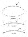
- the term right way out will be taken to refer to a lens fitted in a conventional orientation in which there is an anterior convex surface and a posterior convex surface opposing an eye and the term inside out will be taken to refer to that lens flexed inside out to cause the anterior surface in the right way out orientation to form a posterior convex surface and the posterior surface in the right wary out orientation to form an anterior surface.
- the lens to be described below may be referred to as a 'flipper' or flexing lens due to its ability to be re oriented ( flex) for reorientation on an eye.
- the flexing may be along an axis normal to the lens when viewed in profile by flipping of the lens thereby allowing the lens due to formations introduced into the lens forming relief areas to present to an eye in an inside out or right way out orientation.
- the lens according to the invention satisfies traditional fit and comfort criteria and fits optimally to the eye in either orientation by virtue of flexing of relief areas located in the optical and /or non-optical areas of the contact lens.
- the lens allows for flipping ( flexing) or reorientation of the lens but with clinically acceptable fitting characteristics by way of formations such as bands that are located in the optical or non optical (peripheral area) of the lens.
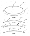
- formations which provide areas of relief are generally thinner un profile than the surrounding areas and are shaped such that they allow the wrapping forces of the lens to be reoriented sympathetically with the general reorientation of the lens.
- formations in the regions of flexure in the peripheral area of the lens may contain at least one circumferential band (or bands) or area (s) that is/are thinner than the immediately surrounding areas of the lens when viewed in cross section.
- the formations providing the relief area(s) is/are positioned in the peripheral area of the lens nearer the lens edge in a selected site that optimizes a resistance relieving role the formations and thus relief areas provide. It (they) can also be placed in the outer areas of the optical zone in such a manner that it (or they) does/do not interfere with the optical performance of the lens.
- the formations in the lens accommodate the flexure by reducing resistance to flexure.
- These thinner or thicker area(s) can be designed controlled accurately by conventional means well known and understood in the art (especially with injection cast moulding means) and can be shaped or graduated in such a way as the designer sees fit in order to provide the wearer with suitable levels of in vivo comfort.
- the lens profile according to one embodiment is specifically thinner in that (or those) area (s) the lens will exhibit less resistance to any non-conformance of wrapping to the lens/scleral profile when presented to same. It will possess discreet and intentional areas of least resistance that will allow the lens to bend or wrap more easily in those areas than others.
- the designer is able to provide the lens with sections of least resistance that coincide with the most appropriate area within the lens that will allow it to conform to the lens scleral profile.
- the designer can create a lens that will conform to the corneal/scleral profile in a compliant and clinically acceptable manner in either orientation.
- the natural resistance to being "inside out” and the abstract and uncontrolled curvature changes that occur as a result will be reduced or eliminated by the relieving areas placed within the lens.
- the natural tendency for an "inside out” lens to curl off the eye when inserted will be eliminated by the reorientation of the wrapping forces.
- the lens may include the use of non-curved surfaces that can be shaped in such a way as to reduce inversion or flexure resistance as much as possible.
- non-curved surfaces or a combination of non-curved and curved surfaces the lens shape can be made to 'flex' inside out very easily.
- the flat sections can be used in conjunction with curved surfaces made from spherical sections.
- the formations introduced into the lens are thicker than adjacent to more conventionally designed areas of the lens This may be required to create a stronger flexing or reorientation force.
- An alternative embodiment of the lens may employ an edge profile of the lens, immediately adjacent to a formation comprising a thinner area of least resistance.
- the lens When viewed in cross section, the lens would exhibit a bi-convex profile which is uniform and identical in profile on both surfaces. This peripheral rim would provide a controlling force on the edge of the lens that would prevent eversion (lifting) and would ensure that the edge demonstrated similar wrapping characteristics in either orientation.
- the uniform design could reflect the posterior and anterior edge shape as a mirror image of each other and thus provide for similar lid interaction profiles no matter which fitting orientation is chosen.
- the edge shapes may also be made from non-curved forms that may be of a flat or straight edged nature.
- a peripheral rim is or edge of the lens is shaped with a slightly differing profile on one face from an opposite face. This could be used, either in conjunction with other design embodiments, or on its own to obtain varying fitting characteristics when fitted in opposing orientation whilst still wrapping appropriately to the sclera.
- Lens fit in either the right way out or inside out orientation will be aided by controlling of the optic zone dimensions and the sharing of the duties of the optic zone between the anterior and posterior surfaces of the lens.
- Traditional soft spherical lenses and some soft toric lenses simply use the posterior surface of the lens for fitting to the eye of the wearer.
- the radius is selected from a fitting standpoint versus a refractive platform and thus becomes a baseline for the final choice of refractive curve on the anterior surface when the final refractive solution is considered.
- the power that is required to satisfy the wearer's prescription is then derived from the anterior surface curvature alone.
- the disparity between the posterior (base curve) radius and the anterior optic radius creates the refractive quantum.
- the aforementioned outline describes a typical soft contact lens in today's market.
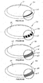
- Some known lenses in the market use a specifically designed discreet refracting segment located in the posterior surface of the lens. It is generally located in the center of the base radius and can be steeper or flatter in radius to the main base curve radius. If it is steeper in radius it will create a more minus effect to the overall refractive power of the lens and if it is flatter it will create a more plus effect to the overall refractive power of the lens.
- This type of refracting segment has proved to be a successful design feature in soft toric lenses and high minus lenses as described in Australian patent no 620083 , United States patent 5,125,728 and European patent 0398984 .
- the primary advantage of such a design feature is in the provision of a means to arbitrarily control and influence the thickness profile and refracting curves of the lens, independent of the curvatures of the eye.
- the fitting and refracting advantages are obvious.
- the designer can create the optimum set of curves to refract the eye with any given lens without being overly restricted by fitting and corneal alignment concerns.
- the use of a selectively designed posterior optical segment is useful as it can enhance or assist the wrapping effect of the lens, when it is placed on the eye in its "inside out” orientation, by virtue of reducing the natural resistance to flexing of the optic junction of the lens.
- a lens has a thicker junction thickness, it will resist reorientation more so than a lens with a thinner junction thickness, as the natural difference between the anterior and posterior curves will be lessened.
- this is particularly relevant as the posterior curve is generally steeper in radius than the anterior curve and will prove more difficult to re-orient away from its natural shape as it increases in thickness. This thickness increase occurs from the center of the lens out to the edge of the optic junction, whereupon it can generally be reduced by the judicious use of closely approximated peripheral curves.
- a minus lens is designed in a conventional manner it will encounter a natural resistance to wrapping or curving in its opposite (or unnatural) orientation as the optic junction will present the lens with an area of resistance.
- the reduction in junction thickness by the use of reduced optic zones can be further enhanced by the use of non-spherical curvatures and shapes that promote a smooth and seamless transition between itself and the surrounding area of the lens. This will improve the wrapping response of the lens when re-orientated even further.
- Such an optical design can also be used in conjunction with a surrounding reliving area (s) similar to the peripheral relieving band (s) so that the lens will wrap even more easily when re-orientated on the eye.
- the relieving area (s) can be positioned in close proximity to the optic junction or in close proximity to the blend (s) that make up the transition from segment to surrounding surface. It will be appreciated by persons skilled in the art of lens design, that many combinations and derivations of the above mentioned design principle are possible.
- the lens includes at least one formation providing a strain relief area within an optical area such that the relief area assists in the reorientation flexing of the lens by reducing natural resistance to flexing when it is positioned on the eye in either the right way out conventional orientation or inverted (flexed) inside out orientation but without compromise to optical effectivity.
- the optic junction is generally constant and can be designed so that it is quite thin.
- the optic thickness however will increase with the strengthening of the lens power and may create a natural resistance to optimal wrapping when re-orientated on the eye.
- a design feature of the lens proposed herein is the reduction in center thickness of the positive powered lens by the use of a posterior optical segment which is less steep in radius than the surrounding curvature (s). This approach will allow the designer to reduce the optical center thickness from that of a conventional designed lens and thus overcome its natural resistance to being "inside out”. This too can be enhanced by the use of an adjacent or nearby formations providing relieving area (s).
- the key to the lens achieving fitting success in either orientation is the reduction, removal or reshaping of those naturally occurring areas of resistance that are created by conventional designs. Once this is achieved and the lens can be fitted either "inside out” or the “right way out", the designer is free to create varying optical effects as mentioned above. Or the designer can create subtle differences in the fitting characteristics of the lens by adjusting the resistance values of anterior versus posterior surfaces.
- a design such as this allows the patient to handle the lens far more easily, not worry about correct orientation prior to insertion and generally just concentrate on enjoying wearing a comfortable lens.
- a lens manufactured in accordance with the invention allows the wearer to select the optimum correction for his or her optical needs at any time by lens fitting orientation.
- a lens such as described before could offer the Practitioner a genuine advantage in prescribing flexibility from both a fitting and optical perspective.
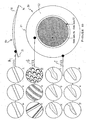
- the lens employs the use of concentrically positioned alternating optical zones or bands that incorporate optical changes and shifts such that the lens in situ can generate a bifocal or multifocal effect.
- the alternating bands could also be designed to create a single vision effect or to create aspheric or other such optical effects the designer should desire. Arranging the alternating bands of differing power or surface geometry on both the anterior and posterior surfaces to create conflicting or complimentary effects could also be useful to the designer.
- the lens uses at least one relieving area within the optical area such that the relieving area assists in the reorientation of the lens when it is positioned on the eye in either it's conventional orientation or inverted orientation. The use of thoughtful design principles could achieve this affect without sacrificing optical effectivity.
- the lens employs such surface geometry which is generated by non-rotationally symmetrical means and such geometry being able to be altered or tailored to the designers wishes by virtue of its orientation on the eye.
- colouration of lenses may be adapted to the lens according to the present invention.
- coloured or opaque tinted contact lenses There has been an increase in the popularity and usage of coloured or opaque tinted contact lenses around the world. These lenses most commonly have a coloured iris pattern printed or bonded on the anterior surface or affixed within the matrix of the lens and are capable of changing the natural eye colour to something new.
- a wearer with brown irides for example can change their eye colour to blue by wearing a pair of blue opaque tinted contact lenses.
- they are coloured in such a way that they are effective on one side of the lens only. This is because the base curve side is always fitted facing the eye and would not benefit from having any specific colour As such there can be only one colour per lens.
- a wearer has the choice of two colours by the simple action of reorienting their lenses on their eyes.
- the anterior side of the lens may be tinted blue whilst the posterior side may be tinted green.
- the patient's eye colour could be either green or blue.
- a lens is provided with colouration on one or both sides of the lens.
- the lens may be prepared with, the same colour on both sides this might be preferred where flexing provides an alternative refractive correction without a colour change upon flexing), two different colours, one on each side.
- the lens may also be prepared with more than one colour on one or both sides.
- the above colour regimes may be employed in the flexing lens irrespective of whether a wearer requires a refractive correction or not. In the case of a coloured lens with no refractive correction the flexing would would be for a cosmetic colour change.
- the lens can be inserted either ... "inside out” or "the right way out” as the designer or wearer chooses. This makes the wearing of contact lenses far more practical for patients as they no longer have to determine which way the lens should be oriented before insertion. According to the invention the lens would fit in a similar manner whichever way it was placed on the eye. This is advantageous for disposable lenses as they can be handled less before being placed on the eye and they would not need to be orientated upon removal from the disposable packaging. This is a very convenient way to handle lenses every day. It would be appreciated by those skilled in the art of contact lens design that a lens designed and manufactured as described herein would not necessarily require any anti-inversion marking because the lens may be placed right way out or inside out.
- the lens may be designed to exhibit a controlled amount of in vivo fitting flexure, epending on its orientation when inserted. This would make the lens useful for optimising a fitting problem without having to resort to the ordering or selecting of a totally new base curve. Both practitioner and patient would find this an advantage depending on the wearer's requirements at the time. An anti-inversion mark would allow the patient to determine the correct orientation.
- the lens can optically capitalise on the refractive changes created when either the anterior or the posterior surfaces of the lens are presented to the corneal/scleral profile.
- the change in surface shape, created by differing wrap effects between the anterior or the posterior surface when either of them are presented to the corneal/scleral profile, may be used to "tune" a lens from the perspective of optimising a refractive result in vivo. Or it may be used to create a mild multifocal effect by way of inducing a planned aspheric or non-spherical shape in vivo and thus create a progressive power shift (this could be in either positive or negative direction in relation to the apical power).
- This type of lens would be very useful to a patient who wanted to wear single vision lenses at times and yet wanted to wear bifocal or multifocal lenses at others.
- the wearer could obtain a bifocal or multifocal effect at their discretion, simply by removing the lenses and reinserting them in their opposing orientation. Alternatively the wearer may find the reorientation of just one of the lenses to be optimal also.
- This design principle allows the wearer to enjoy a very flexible wearing regime, depending on the designs used.
- the lens may also be designed to enhance an otherwise standard monovision fitting regime by offering a choice of at least two power alternatives per lens, depending on the orientation of each of the lenses. This actually creates a possibility of wearing four different powers or four different optical variances from only two lenses. Obviously this presents as a significant advantage to the practitioner and patient alike.
- the above mentioned monovision fitting regime can be further enhanced by virtue of at least one of the lenses being able to create a multifocal effect when worn and being able to vary that multifocal effect when inverted in wearing orientation. This would offer even more flexibility and variability to the practitioner and patient and would allow for far more accurate fine tuning of any given monovision or multifocal fitting regime.
- Another advantageous version of this lens design principle is the enhancement of it's optical advantages or features by the judicious use of freznel or freznel style optical principles.
- a lens manufactured with a diffractive type of optical design principle incorporated, could very easily create alternate optical results when fitted to the eye in both the conventional and opposite orientation.
- the optical eschelets will experience a change in their principle diffracting angles along with the change in wrap effect in vivo when the lens is fitted to the eye in either its conventional or "inside out” orientation.
Landscapes
- Health & Medical Sciences (AREA)
- Ophthalmology & Optometry (AREA)
- Physics & Mathematics (AREA)
- General Health & Medical Sciences (AREA)
- General Physics & Mathematics (AREA)
- Optics & Photonics (AREA)
- Eyeglasses (AREA)
Applications Claiming Priority (3)
| Application Number | Priority Date | Filing Date | Title |
|---|---|---|---|
| AUPR276601 | 2001-01-31 | ||
| AUPR2766A AUPR276601A0 (en) | 2001-01-31 | 2001-01-31 | A contact lens for refractive correction and capable of engagement with an eye either inside out or right way out |
| PCT/AU2002/000098 WO2002061497A1 (en) | 2001-01-31 | 2002-01-31 | A soft contact lens capable of engagement with an eye either right way out or inside out |
Publications (3)
| Publication Number | Publication Date |
|---|---|
| EP1364248A1 EP1364248A1 (en) | 2003-11-26 |
| EP1364248A4 EP1364248A4 (en) | 2005-02-09 |
| EP1364248B1 true EP1364248B1 (en) | 2015-08-12 |
Family
ID=3826793
Family Applications (1)
| Application Number | Title | Priority Date | Filing Date |
|---|---|---|---|
| EP02710680.6A Expired - Lifetime EP1364248B1 (en) | 2001-01-31 | 2002-01-31 | A soft contact lens capable of engagement with an eye either right way out or inside out |
Country Status (12)
| Country | Link |
|---|---|
| US (1) | US7021760B2 (enExample) |
| EP (1) | EP1364248B1 (enExample) |
| JP (2) | JP4310105B2 (enExample) |
| KR (2) | KR100971319B1 (enExample) |
| CN (1) | CN1308733C (enExample) |
| AU (2) | AUPR276601A0 (enExample) |
| CA (1) | CA2435745C (enExample) |
| ES (1) | ES2547238T3 (enExample) |
| NO (1) | NO20033403L (enExample) |
| NZ (1) | NZ527223A (enExample) |
| WO (1) | WO2002061497A1 (enExample) |
| ZA (1) | ZA200305731B (enExample) |
Cited By (2)
| Publication number | Priority date | Publication date | Assignee | Title |
|---|---|---|---|---|
| WO2022064297A1 (en) | 2020-09-24 | 2022-03-31 | Johnson & Johnson Vision Care, Inc. | Cosmetic contact lens with reversible effects |
| RU2842595C1 (ru) * | 2020-09-24 | 2025-06-30 | Джонсон Энд Джонсон Вижн Кэа, Инк. | Косметическая контактная линза с двусторонними эффектами |
Families Citing this family (49)
| Publication number | Priority date | Publication date | Assignee | Title |
|---|---|---|---|---|
| US20060238702A1 (en) | 1999-04-30 | 2006-10-26 | Advanced Medical Optics, Inc. | Ophthalmic lens combinations |
| US7763069B2 (en) | 2002-01-14 | 2010-07-27 | Abbott Medical Optics Inc. | Accommodating intraocular lens with outer support structure |
| US20040085510A1 (en) * | 2002-10-30 | 2004-05-06 | O'brien Keith T. | Contact lenses for correction of irregular corneal surfaces |
| US7662180B2 (en) | 2002-12-05 | 2010-02-16 | Abbott Medical Optics Inc. | Accommodating intraocular lens and method of manufacture thereof |
| US7138638B2 (en) * | 2003-11-20 | 2006-11-21 | Juni Jack E | Edge effects treatment for crystals |
| US20050131535A1 (en) | 2003-12-15 | 2005-06-16 | Randall Woods | Intraocular lens implant having posterior bendable optic |
| US8377123B2 (en) * | 2004-11-10 | 2013-02-19 | Visiogen, Inc. | Method of implanting an intraocular lens |
| JP4674893B2 (ja) * | 2004-12-28 | 2011-04-20 | 株式会社サンコンタクトレンズ | コンタクトレンズ |
| US20070168027A1 (en) * | 2006-01-13 | 2007-07-19 | Brady Daniel G | Accommodating diffractive intraocular lens |
| CA2587097A1 (en) * | 2006-04-12 | 2007-10-12 | Rikke Dootjes | Lens |
| TW200741278A (en) * | 2006-04-28 | 2007-11-01 | Wei-Bin Shiu | Contact lenses |
| US7878650B2 (en) * | 2006-06-29 | 2011-02-01 | Fritsch Michael H | Contact lens materials, designs, substances, and methods |
| US20080013044A1 (en) * | 2006-07-11 | 2008-01-17 | Procornea Nederland B.V. | Contact lens |
| US7862169B2 (en) | 2006-09-29 | 2011-01-04 | Johnson & Johnson Vision Care, Inc. | Contact lenses and methods for their design |
| US20080161914A1 (en) | 2006-12-29 | 2008-07-03 | Advanced Medical Optics, Inc. | Pre-stressed haptic for accommodating intraocular lens |
| TWI487516B (zh) * | 2007-08-22 | 2015-06-11 | Novartis Ag | 老花眼的治療系統 |
| US8034108B2 (en) | 2008-03-28 | 2011-10-11 | Abbott Medical Optics Inc. | Intraocular lens having a haptic that includes a cap |
| EP2259741B1 (en) * | 2008-04-01 | 2017-11-08 | Scientific Optics, Inc. | Universal contact lens posterior surface construction |
| KR100931595B1 (ko) * | 2009-03-12 | 2009-12-14 | 주식회사 지앤에이치 | 엘이디 등기구의 장착장치 |
| WO2010151691A2 (en) | 2009-06-26 | 2010-12-29 | Abbott Medical Optics Inc. | Accommodating intraocular lenses |
| CN101936502A (zh) * | 2009-06-30 | 2011-01-05 | 富准精密工业(深圳)有限公司 | 透镜、发光二极管模组及其应用的照明装置 |
| CN101963322A (zh) * | 2009-07-21 | 2011-02-02 | 富准精密工业(深圳)有限公司 | 透镜、发光二极管模组及照明装置 |
| EP2461768B1 (en) | 2009-08-03 | 2020-02-19 | Johnson & Johnson Surgical Vision, Inc. | Intraocular lens for providing accomodative vision |
| JP5335099B2 (ja) * | 2009-11-17 | 2013-11-06 | 株式会社メニコン | コンタクトレンズ |
| JP4768075B1 (ja) * | 2010-08-25 | 2011-09-07 | 博紀 藤田 | 視力矯正用コンタクトレンズキット |
| US8992611B2 (en) | 2010-09-03 | 2015-03-31 | Abbott Medical Optics Inc. | Microincision lens |
| AU2011320709B2 (en) * | 2010-10-26 | 2015-12-17 | Alcon Inc. | Ophthalmoscopic surgical contact lens |
| US8672476B2 (en) * | 2011-03-24 | 2014-03-18 | Johnson & Johnson Vision Care, Inc. | Contact lenses with improved movement |
| WO2012166570A1 (en) * | 2011-06-01 | 2012-12-06 | Bausch & Lomb Incorporated | Contact lenses having hybrid orientation features |
| CN102262307A (zh) * | 2011-08-17 | 2011-11-30 | 陈迪生 | 一种新型软性角膜接触镜 |
| JP5536265B2 (ja) * | 2013-07-30 | 2014-07-02 | 株式会社メニコン | コンタクトレンズ |
| US20160223429A1 (en) * | 2013-09-11 | 2016-08-04 | Novartis Ag | Contact lens inspection system and method |
| WO2015060211A1 (ja) * | 2013-10-21 | 2015-04-30 | 株式会社メニコン | コンタクトレンズ |
| US9389434B2 (en) | 2013-11-22 | 2016-07-12 | Johnson & Johnson Vision Care, Inc. | Contact lenses with improved oxygen transmission |
| US20150248019A1 (en) * | 2014-02-28 | 2015-09-03 | Johnson & Johnson Vision Care, Inc. | Contact lenses with apparent motion and other optical effects |
| US9412029B2 (en) * | 2014-12-12 | 2016-08-09 | Iris Id, Inc. | Apparatus for recognizing iris and operating method thereof |
| WO2017013644A2 (en) * | 2015-07-22 | 2017-01-26 | Pres-By Vision Ltd | Contact lens for vision correction |
| US10274751B2 (en) * | 2016-07-05 | 2019-04-30 | Bausch & Lomb Incorporated | Prism ballasted contact lens |
| CA3075214A1 (en) | 2017-09-11 | 2019-03-14 | Amo Groningen B.V. | Methods and apparatuses to increase intraocular lenses positional stability |
| EP3846739A4 (en) * | 2018-09-04 | 2022-02-09 | Pres-by Vision Ltd. | MECHANISMS FOR INDUCING TRANSITIONS IN DYNAMIC CONTACT LENSES |
| JP7111244B2 (ja) | 2019-02-28 | 2022-08-02 | オムロン株式会社 | 光電センサ及びその製造方法 |
| US11221499B2 (en) * | 2019-03-29 | 2022-01-11 | Johnson & Johnson Vision Care, Inc. | Invertible lens and method of design |
| CN113093405B (zh) * | 2020-01-08 | 2023-05-26 | 星欧光学股份有限公司 | 隐形眼镜及隐形眼镜产品 |
| US11762220B2 (en) * | 2020-04-30 | 2023-09-19 | Coopervision International Limited | Multifocal ophthalmic lenses and related methods |
| US11934043B2 (en) | 2020-04-30 | 2024-03-19 | Coopervision International Limited | Myopia control lens and related methods |
| US20220113558A1 (en) * | 2020-10-13 | 2022-04-14 | Johnson & Johnson Vision Care, Inc. | Contact lens position and rotation control using the pressure of the eyelid margin |
| CN112666723B (zh) * | 2020-12-31 | 2021-11-16 | 菲特兰有限公司 | 具有开窗和凹袋的巩膜镜 |
| KR102768899B1 (ko) * | 2022-10-18 | 2025-02-18 | 정성희 | 이물 제거용 콘택트렌즈 |
| GB202402937D0 (en) * | 2024-02-29 | 2024-04-17 | Coopervision Int Ltd | Contact lenses with inversion marks |
Citations (1)
| Publication number | Priority date | Publication date | Assignee | Title |
|---|---|---|---|---|
| US4896958A (en) * | 1988-02-18 | 1990-01-30 | Ames Keith S | Flexible contact lens for enhanced movement on the eye |
Family Cites Families (53)
| Publication number | Priority date | Publication date | Assignee | Title |
|---|---|---|---|---|
| US3468602A (en) * | 1966-07-11 | 1969-09-23 | Hyman Rosen | Contact lens with flexible central portion |
| US3950082A (en) * | 1973-01-10 | 1976-04-13 | David Volk | Ophthalmic lens for presbyopia and aphakia |
| FR2248527A1 (en) * | 1973-10-19 | 1975-05-16 | Lagouche Pierre | Extensible corneal lenses of rigid plastic material - incorporating narrow hinge zones of flexible material |
| US4190621A (en) * | 1977-03-10 | 1980-02-26 | Martin Greshes | Method for molding optical plastic lenses of the standard and bifocal type |
| US4113088A (en) * | 1977-06-06 | 1978-09-12 | Binkhorst Richard D | Sterile package |
| DE2749144C2 (de) * | 1977-11-03 | 1979-12-06 | Bruno 6000 Frankfurt Koller | Kontaktlinse |
| FR2416104A1 (fr) * | 1978-02-07 | 1979-08-31 | Essilor Int | Dispositif de moulage, en particulier pour lentille de contact souple |
| US4173281A (en) * | 1978-06-12 | 1979-11-06 | Intermedics Intraocular, Inc. | Intraocular lens packaging system |
| US4392569A (en) * | 1979-06-06 | 1983-07-12 | Shoup Leo E | Soft contact lens asepticizing case |
| US4257521A (en) * | 1979-11-16 | 1981-03-24 | Stanley Poler | Packaging means for an intraocular lens |
| US4284399A (en) * | 1980-06-23 | 1981-08-18 | American Optical Corporation | Contact lens mold |
| DE3037252C2 (de) * | 1980-10-02 | 1983-12-29 | Wilhelm Rogg Kunststoff-Metallisierung, 8500 Nürnberg | Spritzgießform zum Herstellen von Formkörpern aus zwei Kunststoffarten |
| US4423809A (en) * | 1982-02-05 | 1984-01-03 | Staar Surgical Company, Inc. | Packaging system for intraocular lens structures |
| US4616910A (en) * | 1983-03-01 | 1986-10-14 | Klein Robert E | Visual indicator on soft contact lenses |
| US4618227A (en) * | 1983-10-07 | 1986-10-21 | Vistakon, Inc. | Soft contact lens |
| CA1265688A (en) * | 1984-10-17 | 1990-02-13 | Alain Rainville | Bi-focal corneal lens and method of making the same |
| US4691820A (en) * | 1985-11-18 | 1987-09-08 | Vistakon, Inc. | Package for hydrophilic contact lens |
| US4890912A (en) * | 1986-01-24 | 1990-01-02 | Rients Visser | Trifocal eye-contact lens |
| US5176686A (en) * | 1987-03-26 | 1993-01-05 | Poley Brooks J | Apparatus for packaging, folding, rigidifying and inserting an intraocular lens |
| US4850689A (en) * | 1988-03-07 | 1989-07-25 | Bruce A. Martin | Near vision contact lens and methods of making and using it |
| US5062701A (en) * | 1988-06-07 | 1991-11-05 | Wesley-Jessen Corporation | Asymmetric contact lens |
| US4923296A (en) * | 1988-07-14 | 1990-05-08 | Erickson Paul M | Oriented simultaneous vision bifocal contact lenses or the like utilizing introaocular suppression of blur |
| US4944580A (en) * | 1988-07-27 | 1990-07-31 | Thermo Electron Technologies Corp. | Active segmented mirror including a plurality of piezoelectric drivers |
| US4830481A (en) * | 1988-08-12 | 1989-05-16 | Minnesota Mining And Manufacturing Company | Multifocal diffractive lens |
| US5076683A (en) * | 1988-09-14 | 1991-12-31 | Allergan, Inc. | Spuncast compound contact lens |
| CA2009668A1 (en) * | 1989-02-16 | 1990-08-16 | Ashok R. Thakrar | Colored contact lenses and method of making same |
| US5054610A (en) * | 1989-05-31 | 1991-10-08 | Ciba-Geigy Corporation | Disposable single-use contact lens conditioning package |
| US5080839A (en) * | 1990-04-17 | 1992-01-14 | Johnson & Johnson Vision Products, Inc. | Process for hydrating soft contact lenses |
| US5349395A (en) * | 1991-08-23 | 1994-09-20 | Nick Stoyan | Multiple focus corneal contact lens and method for treating myopia |
| US5191365B1 (en) * | 1991-08-23 | 2000-08-15 | Contex Inc | Corneal contact lens and method for treating myopia |
| US5271875A (en) * | 1991-09-12 | 1993-12-21 | Bausch & Lomb Incorporated | Method for molding lenses |
| JP2934133B2 (ja) * | 1992-10-27 | 1999-08-16 | 株式会社メニコン | ソフトコンタクトレンズ |
| US5448312A (en) * | 1992-12-09 | 1995-09-05 | Johnson & Johnson Vision Products, Inc. | Pupil-tuned multifocal ophthalmic lens |
| US5436678A (en) * | 1993-09-30 | 1995-07-25 | Wilmington Partners L.P. | Aspheric multifocal contact lens |
| US5517260A (en) * | 1994-03-28 | 1996-05-14 | Vari-Site, Inc. | Ophthalmic lens having a progressive multifocal zone and method of manufacturing same |
| US5635998A (en) * | 1994-12-06 | 1997-06-03 | Baugh; Thomas K. | Translating multifocal contact lens |
| IL118065A0 (en) * | 1995-05-04 | 1996-08-04 | Johnson & Johnson Vision Prod | Aspheric toric lens designs |
| US5684560A (en) * | 1995-05-04 | 1997-11-04 | Johnson & Johnson Vision Products, Inc. | Concentric ring single vision lens designs |
| US5936704A (en) * | 1997-12-22 | 1999-08-10 | Gabrielian; Grant | Marked contact lens bearing optical marking element |
| US6030077A (en) * | 1998-03-11 | 2000-02-29 | Menicon Co., Ltd. | Multifocal ocular lens having intermediate region with continuously varying optical power |
| US6260966B1 (en) | 1998-03-11 | 2001-07-17 | Menicon Co. Ltd. | Multifocal ocular lens |
| AU5545699A (en) | 1998-08-06 | 2000-02-28 | John B. W. Lett | Multifocal aspheric lens |
| JP3804894B2 (ja) | 1998-08-26 | 2006-08-02 | 株式会社メニコン | 老視矯正用コンタクトレンズ |
| JP2000122006A (ja) | 1998-10-16 | 2000-04-28 | Menicon Co Ltd | 多焦点型眼用レンズ |
| WO2000054094A1 (en) | 1999-03-12 | 2000-09-14 | Bausch & Lomb Incorporated | Multifocal lens article |
| US6206520B1 (en) | 1999-03-25 | 2001-03-27 | Johnson & Johnson Vision Care, Inc. | Contact lenses with contoured edges |
| DE19933775A1 (de) | 1999-07-19 | 2001-02-08 | Hecht Gmbh Kontaktlinsen | Contactlinse bzw. Intraokularlinse mit Fern- und Nahwirkungszonen |
| US6511178B1 (en) | 1999-07-19 | 2003-01-28 | Johnson & Johnson Vision Care, Inc. | Multifocal ophthalmic lenses and processes for their production |
| US6364483B1 (en) | 2000-02-22 | 2002-04-02 | Holo Or Ltd. | Simultaneous multifocal contact lens and method of utilizing same for treating visual disorders |
| US6467903B1 (en) | 2000-03-31 | 2002-10-22 | Ocular Sciences, Inc. | Contact lens having a uniform horizontal thickness profile |
| US6322215B1 (en) | 2000-08-07 | 2001-11-27 | Alexander C. Bristol | Non-progressive trifocal ophthalmic lens |
| US6474814B1 (en) | 2000-09-08 | 2002-11-05 | Florida Optical Engineering, Inc | Multifocal ophthalmic lens with induced aperture |
| US6746118B2 (en) | 2001-07-17 | 2004-06-08 | Soft Focal Company, Inc. | Bifocal contact lens with secondary prism |
-
2001
- 2001-01-31 AU AUPR2766A patent/AUPR276601A0/en not_active Abandoned
-
2002
- 2002-01-31 KR KR1020087027214A patent/KR100971319B1/ko not_active Expired - Fee Related
- 2002-01-31 EP EP02710680.6A patent/EP1364248B1/en not_active Expired - Lifetime
- 2002-01-31 WO PCT/AU2002/000098 patent/WO2002061497A1/en not_active Ceased
- 2002-01-31 KR KR10-2003-7010044A patent/KR20040043110A/ko not_active Ceased
- 2002-01-31 CN CNB028074718A patent/CN1308733C/zh not_active Expired - Lifetime
- 2002-01-31 NZ NZ527223A patent/NZ527223A/en unknown
- 2002-01-31 ES ES02710680.6T patent/ES2547238T3/es not_active Expired - Lifetime
- 2002-01-31 CA CA 2435745 patent/CA2435745C/en not_active Expired - Fee Related
- 2002-01-31 AU AU2002229400A patent/AU2002229400B2/en not_active Ceased
- 2002-01-31 JP JP2002562007A patent/JP4310105B2/ja not_active Expired - Fee Related
- 2002-01-31 US US10/470,903 patent/US7021760B2/en not_active Expired - Lifetime
-
2003
- 2003-07-24 ZA ZA200305731A patent/ZA200305731B/en unknown
- 2003-07-30 NO NO20033403A patent/NO20033403L/no not_active Application Discontinuation
-
2009
- 2009-02-06 JP JP2009025795A patent/JP4870789B2/ja not_active Expired - Fee Related
Patent Citations (1)
| Publication number | Priority date | Publication date | Assignee | Title |
|---|---|---|---|---|
| US4896958A (en) * | 1988-02-18 | 1990-01-30 | Ames Keith S | Flexible contact lens for enhanced movement on the eye |
Cited By (3)
| Publication number | Priority date | Publication date | Assignee | Title |
|---|---|---|---|---|
| WO2022064297A1 (en) | 2020-09-24 | 2022-03-31 | Johnson & Johnson Vision Care, Inc. | Cosmetic contact lens with reversible effects |
| US11520166B2 (en) | 2020-09-24 | 2022-12-06 | Johnson & Johnson Vision Care, Inc. | Cosmetic contact lens with reversible effects |
| RU2842595C1 (ru) * | 2020-09-24 | 2025-06-30 | Джонсон Энд Джонсон Вижн Кэа, Инк. | Косметическая контактная линза с двусторонними эффектами |
Also Published As
| Publication number | Publication date |
|---|---|
| JP2009139974A (ja) | 2009-06-25 |
| US20040061828A1 (en) | 2004-04-01 |
| CN1308733C (zh) | 2007-04-04 |
| KR100971319B1 (ko) | 2010-07-20 |
| ES2547238T3 (es) | 2015-10-02 |
| JP4870789B2 (ja) | 2012-02-08 |
| NO20033403L (no) | 2003-09-29 |
| KR20080100294A (ko) | 2008-11-14 |
| EP1364248A1 (en) | 2003-11-26 |
| CA2435745A1 (en) | 2002-08-08 |
| AUPR276601A0 (en) | 2001-02-22 |
| CN1507576A (zh) | 2004-06-23 |
| WO2002061497A1 (en) | 2002-08-08 |
| ZA200305731B (en) | 2004-08-27 |
| US7021760B2 (en) | 2006-04-04 |
| JP4310105B2 (ja) | 2009-08-05 |
| AU2002229400B2 (en) | 2007-03-01 |
| JP2004522183A (ja) | 2004-07-22 |
| NO20033403D0 (no) | 2003-07-30 |
| CA2435745C (en) | 2008-08-05 |
| KR20040043110A (ko) | 2004-05-22 |
| NZ527223A (en) | 2005-09-30 |
| EP1364248A4 (en) | 2005-02-09 |
Similar Documents
| Publication | Publication Date | Title |
|---|---|---|
| EP1364248B1 (en) | A soft contact lens capable of engagement with an eye either right way out or inside out | |
| AU2002229400A1 (en) | A soft contact lens capable of engagement with an eye either right way out or inside out | |
| EP0102223B1 (en) | Bifocal soft contact lens | |
| US6685315B1 (en) | Bifocal lenses | |
| JP4442927B2 (ja) | 傾斜装用型コンタクトレンズ | |
| TWI481921B (zh) | 轉換式老花隱形眼鏡 | |
| EP2411861B1 (en) | Contact lens with meridional sagittal variation and methods for making and using the same | |
| JP4850717B2 (ja) | 二焦点コンタクトレンズ | |
| TWI587019B (zh) | 轉換式老花隱形眼鏡(二) | |
| IL104249A (en) | Multifocal ophthalmic lens is divided with a free axis | |
| TWI587018B (zh) | 轉換式老花隱形眼鏡 | |
| JP2002350787A (ja) | コンタクトレンズ | |
| JP5026291B2 (ja) | 装用方向選択型コンタクトレンズ | |
| CN116931289A (zh) | 辐射式点对点隐形眼镜 | |
| CN116931290A (zh) | 同心式点对点隐形眼镜 | |
| HK1187689A (en) | Asymmetric translating presbyopic contact lens | |
| HK1187689B (en) | Asymmetric translating presbyopic contact lens |
Legal Events
| Date | Code | Title | Description |
|---|---|---|---|
| PUAI | Public reference made under article 153(3) epc to a published international application that has entered the european phase |
Free format text: ORIGINAL CODE: 0009012 |
|
| 17P | Request for examination filed |
Effective date: 20030818 |
|
| AK | Designated contracting states |
Kind code of ref document: A1 Designated state(s): AT BE CH CY DE DK ES FI FR GB GR IE IT LI LU MC NL PT SE TR |
|
| AX | Request for extension of the european patent |
Extension state: AL LT LV MK RO SI |
|
| RAP1 | Party data changed (applicant data changed or rights of an application transferred) |
Owner name: NEWMAN, STEPHEN DONALD |
|
| RAP1 | Party data changed (applicant data changed or rights of an application transferred) |
Owner name: CLEARLAB PTE. LTD. |
|
| RAP1 | Party data changed (applicant data changed or rights of an application transferred) |
Owner name: CLEARLAB INTERNATIONAL PTE. LTD. |
|
| REG | Reference to a national code |
Ref country code: HK Ref legal event code: DE Ref document number: 1060770 Country of ref document: HK |
|
| A4 | Supplementary search report drawn up and despatched |
Effective date: 20041229 |
|
| RAP1 | Party data changed (applicant data changed or rights of an application transferred) |
Owner name: MENICON CO., LTD. |
|
| 17Q | First examination report despatched |
Effective date: 20090218 |
|
| REG | Reference to a national code |
Ref country code: HK Ref legal event code: WD Ref document number: 1060770 Country of ref document: HK |
|
| RAP1 | Party data changed (applicant data changed or rights of an application transferred) |
Owner name: MENICON SINGAPORE PTE LTD. |
|
| GRAP | Despatch of communication of intention to grant a patent |
Free format text: ORIGINAL CODE: EPIDOSNIGR1 |
|
| INTG | Intention to grant announced |
Effective date: 20141107 |
|
| GRAS | Grant fee paid |
Free format text: ORIGINAL CODE: EPIDOSNIGR3 |
|
| GRAP | Despatch of communication of intention to grant a patent |
Free format text: ORIGINAL CODE: EPIDOSNIGR1 |
|
| INTG | Intention to grant announced |
Effective date: 20150602 |
|
| GRAA | (expected) grant |
Free format text: ORIGINAL CODE: 0009210 |
|
| AK | Designated contracting states |
Kind code of ref document: B1 Designated state(s): AT BE CH CY DE DK ES FI FR GB GR IE IT LI LU MC NL PT SE TR |
|
| REG | Reference to a national code |
Ref country code: GB Ref legal event code: FG4D |
|
| REG | Reference to a national code |
Ref country code: CH Ref legal event code: EP |
|
| REG | Reference to a national code |
Ref country code: AT Ref legal event code: REF Ref document number: 742659 Country of ref document: AT Kind code of ref document: T Effective date: 20150815 |
|
| REG | Reference to a national code |
Ref country code: IE Ref legal event code: FG4D |
|
| REG | Reference to a national code |
Ref country code: DE Ref legal event code: R096 Ref document number: 60247381 Country of ref document: DE |
|
| REG | Reference to a national code |
Ref country code: ES Ref legal event code: FG2A Ref document number: 2547238 Country of ref document: ES Kind code of ref document: T3 Effective date: 20151002 |
|
| REG | Reference to a national code |
Ref country code: NL Ref legal event code: FP |
|
| REG | Reference to a national code |
Ref country code: AT Ref legal event code: MK05 Ref document number: 742659 Country of ref document: AT Kind code of ref document: T Effective date: 20150812 |
|
| REG | Reference to a national code |
Ref country code: FR Ref legal event code: PLFP Year of fee payment: 15 |
|
| PG25 | Lapsed in a contracting state [announced via postgrant information from national office to epo] |
Ref country code: FI Free format text: LAPSE BECAUSE OF FAILURE TO SUBMIT A TRANSLATION OF THE DESCRIPTION OR TO PAY THE FEE WITHIN THE PRESCRIBED TIME-LIMIT Effective date: 20150812 Ref country code: GR Free format text: LAPSE BECAUSE OF FAILURE TO SUBMIT A TRANSLATION OF THE DESCRIPTION OR TO PAY THE FEE WITHIN THE PRESCRIBED TIME-LIMIT Effective date: 20151113 |
|
| PG25 | Lapsed in a contracting state [announced via postgrant information from national office to epo] |
Ref country code: SE Free format text: LAPSE BECAUSE OF FAILURE TO SUBMIT A TRANSLATION OF THE DESCRIPTION OR TO PAY THE FEE WITHIN THE PRESCRIBED TIME-LIMIT Effective date: 20150812 Ref country code: PT Free format text: LAPSE BECAUSE OF FAILURE TO SUBMIT A TRANSLATION OF THE DESCRIPTION OR TO PAY THE FEE WITHIN THE PRESCRIBED TIME-LIMIT Effective date: 20151214 Ref country code: AT Free format text: LAPSE BECAUSE OF FAILURE TO SUBMIT A TRANSLATION OF THE DESCRIPTION OR TO PAY THE FEE WITHIN THE PRESCRIBED TIME-LIMIT Effective date: 20150812 |
|
| PG25 | Lapsed in a contracting state [announced via postgrant information from national office to epo] |
Ref country code: DK Free format text: LAPSE BECAUSE OF FAILURE TO SUBMIT A TRANSLATION OF THE DESCRIPTION OR TO PAY THE FEE WITHIN THE PRESCRIBED TIME-LIMIT Effective date: 20150812 |
|
| REG | Reference to a national code |
Ref country code: DE Ref legal event code: R097 Ref document number: 60247381 Country of ref document: DE |
|
| PG25 | Lapsed in a contracting state [announced via postgrant information from national office to epo] |
Ref country code: BE Free format text: LAPSE BECAUSE OF NON-PAYMENT OF DUE FEES Effective date: 20160131 |
|
| PLBE | No opposition filed within time limit |
Free format text: ORIGINAL CODE: 0009261 |
|
| STAA | Information on the status of an ep patent application or granted ep patent |
Free format text: STATUS: NO OPPOSITION FILED WITHIN TIME LIMIT |
|
| 26N | No opposition filed |
Effective date: 20160513 |
|
| PG25 | Lapsed in a contracting state [announced via postgrant information from national office to epo] |
Ref country code: LU Free format text: LAPSE BECAUSE OF FAILURE TO SUBMIT A TRANSLATION OF THE DESCRIPTION OR TO PAY THE FEE WITHIN THE PRESCRIBED TIME-LIMIT Effective date: 20160131 |
|
| REG | Reference to a national code |
Ref country code: CH Ref legal event code: PL |
|
| PG25 | Lapsed in a contracting state [announced via postgrant information from national office to epo] |
Ref country code: MC Free format text: LAPSE BECAUSE OF FAILURE TO SUBMIT A TRANSLATION OF THE DESCRIPTION OR TO PAY THE FEE WITHIN THE PRESCRIBED TIME-LIMIT Effective date: 20150812 |
|
| PG25 | Lapsed in a contracting state [announced via postgrant information from national office to epo] |
Ref country code: LI Free format text: LAPSE BECAUSE OF NON-PAYMENT OF DUE FEES Effective date: 20160131 Ref country code: CH Free format text: LAPSE BECAUSE OF NON-PAYMENT OF DUE FEES Effective date: 20160131 |
|
| PG25 | Lapsed in a contracting state [announced via postgrant information from national office to epo] |
Ref country code: BE Free format text: LAPSE BECAUSE OF FAILURE TO SUBMIT A TRANSLATION OF THE DESCRIPTION OR TO PAY THE FEE WITHIN THE PRESCRIBED TIME-LIMIT Effective date: 20150812 |
|
| REG | Reference to a national code |
Ref country code: FR Ref legal event code: PLFP Year of fee payment: 16 |
|
| REG | Reference to a national code |
Ref country code: FR Ref legal event code: PLFP Year of fee payment: 17 |
|
| PG25 | Lapsed in a contracting state [announced via postgrant information from national office to epo] |
Ref country code: CY Free format text: LAPSE BECAUSE OF FAILURE TO SUBMIT A TRANSLATION OF THE DESCRIPTION OR TO PAY THE FEE WITHIN THE PRESCRIBED TIME-LIMIT Effective date: 20150812 |
|
| PG25 | Lapsed in a contracting state [announced via postgrant information from national office to epo] |
Ref country code: TR Free format text: LAPSE BECAUSE OF FAILURE TO SUBMIT A TRANSLATION OF THE DESCRIPTION OR TO PAY THE FEE WITHIN THE PRESCRIBED TIME-LIMIT Effective date: 20150812 |
|
| PGFP | Annual fee paid to national office [announced via postgrant information from national office to epo] |
Ref country code: FR Payment date: 20201210 Year of fee payment: 20 |
|
| PGFP | Annual fee paid to national office [announced via postgrant information from national office to epo] |
Ref country code: IE Payment date: 20210111 Year of fee payment: 20 Ref country code: NL Payment date: 20210113 Year of fee payment: 20 |
|
| PGFP | Annual fee paid to national office [announced via postgrant information from national office to epo] |
Ref country code: ES Payment date: 20210205 Year of fee payment: 20 Ref country code: GB Payment date: 20210120 Year of fee payment: 20 Ref country code: DE Payment date: 20210119 Year of fee payment: 20 |
|
| PGFP | Annual fee paid to national office [announced via postgrant information from national office to epo] |
Ref country code: IT Payment date: 20201211 Year of fee payment: 20 |
|
| REG | Reference to a national code |
Ref country code: DE Ref legal event code: R071 Ref document number: 60247381 Country of ref document: DE |
|
| REG | Reference to a national code |
Ref country code: NL Ref legal event code: MK Effective date: 20220130 |
|
| REG | Reference to a national code |
Ref country code: GB Ref legal event code: PE20 Expiry date: 20220130 |
|
| REG | Reference to a national code |
Ref country code: IE Ref legal event code: MK9A |
|
| PG25 | Lapsed in a contracting state [announced via postgrant information from national office to epo] |
Ref country code: IE Free format text: LAPSE BECAUSE OF EXPIRATION OF PROTECTION Effective date: 20220131 Ref country code: GB Free format text: LAPSE BECAUSE OF EXPIRATION OF PROTECTION Effective date: 20220130 |
|
| REG | Reference to a national code |
Ref country code: ES Ref legal event code: FD2A Effective date: 20220526 |
|
| PG25 | Lapsed in a contracting state [announced via postgrant information from national office to epo] |
Ref country code: ES Free format text: LAPSE BECAUSE OF EXPIRATION OF PROTECTION Effective date: 20220201 |
|
| P01 | Opt-out of the competence of the unified patent court (upc) registered |
Effective date: 20230524 |