EP1363388A2 - Verfahren und Vorrichtung zur Steuerung einer zu einem mehrphasen schaltbaren Gleichstrom-Wechselstrom-Frequenzwandler angeschlossenen elektrischen Last - Google Patents
Verfahren und Vorrichtung zur Steuerung einer zu einem mehrphasen schaltbaren Gleichstrom-Wechselstrom-Frequenzwandler angeschlossenen elektrischen Last Download PDFInfo
- Publication number
- EP1363388A2 EP1363388A2 EP03075753A EP03075753A EP1363388A2 EP 1363388 A2 EP1363388 A2 EP 1363388A2 EP 03075753 A EP03075753 A EP 03075753A EP 03075753 A EP03075753 A EP 03075753A EP 1363388 A2 EP1363388 A2 EP 1363388A2
- Authority
- EP
- European Patent Office
- Prior art keywords
- dead zone
- current
- voltage
- frequency convertor
- realised
- Prior art date
- Legal status (The legal status is an assumption and is not a legal conclusion. Google has not performed a legal analysis and makes no representation as to the accuracy of the status listed.)
- Granted
Links
- 238000000034 method Methods 0.000 title claims abstract description 40
- 230000004907 flux Effects 0.000 claims description 19
- 230000003247 decreasing effect Effects 0.000 claims description 7
- 239000013598 vector Substances 0.000 description 28
- 230000009471 action Effects 0.000 description 5
- 230000008859 change Effects 0.000 description 4
- 239000011159 matrix material Substances 0.000 description 4
- 239000003990 capacitor Substances 0.000 description 3
- 238000010586 diagram Methods 0.000 description 3
- 230000000694 effects Effects 0.000 description 3
- 230000006698 induction Effects 0.000 description 3
- 238000012545 processing Methods 0.000 description 3
- 239000004065 semiconductor Substances 0.000 description 3
- 230000001360 synchronised effect Effects 0.000 description 3
- 230000008901 benefit Effects 0.000 description 2
- 238000001914 filtration Methods 0.000 description 2
- 230000006870 function Effects 0.000 description 2
- 238000003491 array Methods 0.000 description 1
- 230000002457 bidirectional effect Effects 0.000 description 1
- 238000004364 calculation method Methods 0.000 description 1
- 238000012937 correction Methods 0.000 description 1
- 238000013461 design Methods 0.000 description 1
- 238000006073 displacement reaction Methods 0.000 description 1
- 230000005611 electricity Effects 0.000 description 1
- 238000009434 installation Methods 0.000 description 1
- 230000010354 integration Effects 0.000 description 1
- 238000005259 measurement Methods 0.000 description 1
- 230000010363 phase shift Effects 0.000 description 1
- 230000009467 reduction Effects 0.000 description 1
- 238000004804 winding Methods 0.000 description 1
- 230000003936 working memory Effects 0.000 description 1
Images
Classifications
-
- H—ELECTRICITY
- H02—GENERATION; CONVERSION OR DISTRIBUTION OF ELECTRIC POWER
- H02M—APPARATUS FOR CONVERSION BETWEEN AC AND AC, BETWEEN AC AND DC, OR BETWEEN DC AND DC, AND FOR USE WITH MAINS OR SIMILAR POWER SUPPLY SYSTEMS; CONVERSION OF DC OR AC INPUT POWER INTO SURGE OUTPUT POWER; CONTROL OR REGULATION THEREOF
- H02M7/00—Conversion of AC power input into DC power output; Conversion of DC power input into AC power output
- H02M7/42—Conversion of DC power input into AC power output without possibility of reversal
- H02M7/44—Conversion of DC power input into AC power output without possibility of reversal by static converters
- H02M7/48—Conversion of DC power input into AC power output without possibility of reversal by static converters using discharge tubes with control electrode or semiconductor devices with control electrode
- H02M7/53—Conversion of DC power input into AC power output without possibility of reversal by static converters using discharge tubes with control electrode or semiconductor devices with control electrode using devices of a triode or transistor type requiring continuous application of a control signal
- H02M7/537—Conversion of DC power input into AC power output without possibility of reversal by static converters using discharge tubes with control electrode or semiconductor devices with control electrode using devices of a triode or transistor type requiring continuous application of a control signal using semiconductor devices only, e.g. single switched pulse inverters
- H02M7/5387—Conversion of DC power input into AC power output without possibility of reversal by static converters using discharge tubes with control electrode or semiconductor devices with control electrode using devices of a triode or transistor type requiring continuous application of a control signal using semiconductor devices only, e.g. single switched pulse inverters in a bridge configuration
- H02M7/53871—Conversion of DC power input into AC power output without possibility of reversal by static converters using discharge tubes with control electrode or semiconductor devices with control electrode using devices of a triode or transistor type requiring continuous application of a control signal using semiconductor devices only, e.g. single switched pulse inverters in a bridge configuration with automatic control of output voltage or current
- H02M7/53875—Conversion of DC power input into AC power output without possibility of reversal by static converters using discharge tubes with control electrode or semiconductor devices with control electrode using devices of a triode or transistor type requiring continuous application of a control signal using semiconductor devices only, e.g. single switched pulse inverters in a bridge configuration with automatic control of output voltage or current with analogue control of three-phase output
- H02M7/53876—Conversion of DC power input into AC power output without possibility of reversal by static converters using discharge tubes with control electrode or semiconductor devices with control electrode using devices of a triode or transistor type requiring continuous application of a control signal using semiconductor devices only, e.g. single switched pulse inverters in a bridge configuration with automatic control of output voltage or current with analogue control of three-phase output based on synthesising a desired voltage vector via the selection of appropriate fundamental voltage vectors, and corresponding dwelling times
Definitions
- the invention relates to a method for realising an effective value of a quantity to be varied in an electrical load connected to a multi-phase switchable DC/AC frequency convertor comprising a plurality of controllable switches.
- An electrical load within the context of the present invention is e.g. a controllable electrical drive unit consisting of a multi-phase (usually three-phase) electric motor, whose windings are connected to the frequency convertor.
- the frequency convertor is fed with direct current, which direct current is converted into a controllable alternating current by suitably turning the switches of the frequency convertor on and off. Consequently, the frequency convertor converts a direct current voltage (DC) into an alternating current voltage (AC) having an adjustable amplitude and frequency.
- DC direct current voltage
- AC alternating current voltage
- invertor In English professional literature, such frequency convertors are also indicated by the term "invertor".
- electrical loads within the context of the present invention are e.g. transformers, power resistors and the like, for alternating current such loads have a "high-frequency impedance" sufficiently higher than zero for control by a VSI, or a "high-frequency impedance" sufficiently close to zero for control by a CSI.
- a three-phase VSI consists of six unidirectional controllable switches, usually IBGT- or GTO-type semiconductor switches, and one or more capacitors as a DC interstage circuit buffer.
- a three-phase CSI likewise comprises six unidirectional controllable switches, but on the other hand it comprises an induction coil as the DC interstage circuit buffer.
- a matrix convertor does not comprise an interstage circuit, but in its simplest three-phase form it comprises nine bidirectional controllable switches.
- the advantage of the VSI is that it can be fed from a passive rectifier, whereas a CSI needs an invertor as the connection to the power-supplying electricity grid.
- a CSI by definition behaves like a current source at its output terminals, whereas the VSI behaves like a voltage source and the matrix convertor exhibits the input impedance.
- a VSI is generally used in practice, for example for realising a desired motor current in an electric motor, which VSI is controlled in such a manner that the desired motor current will flow in the electric motor.
- the voltage delivered by the VSI will have to be varied.
- the use of a desired voltage value related to the motor current to be realised has a delaying effect on the speed at which the motor current can be adjusted, however.
- a current-controlled VSI strongly depend on the parameters and the working point of the connected electric motor. That is, in those cases in which the motor parameters are subject to change, or in the case of strongly varying loads, a current-controlled VSI functions anything but optimally.
- An example of this is a large linear electric motor whose stator is switched in portions, so that the inductivity will change in steps.
- the method according to the invention is based on the recognition that, by defining a dead zone which is indicative of the allowable amplitude and phase angle deviations in the quantity to be realised and by suitably orienting the dead zone with respect to the voltage or current delivered by the frequency convertor, information for the switching of one or more of the switches of the frequency convertor can be obtained from the manner in which the deviation in the realised quantity extends beyond the dead zone, in such a manner that the deviation in the quantity will be reduced to a value within the range of allowable amplitude and phase angle deviations again.
- the dead zone is quadrangular in shape, preferably square, having opposing first and second boundary lines and opposing third and fourth boundary lines.
- information that is needed for suitably controlling the switches can be derived from the fact that a respective boundary line of the dead zone is being crossed.
- the number of switching moments of the frequency convertor for effecting the desired value of the quantity to be varied can be minimised by adopting suitable switching rules.
- the dimensions of the dead zone are selected in dependence on the allowable amplitude and/or phase angle deviation with which the quantity to be varied may be realised. This may vary from application to application, of course. A larger dead zone will lead to fewer switching actions than a relatively smaller switching area or dead zone.
- the dimensions of the dead zone can be separately set in various directions. In the case of a rectangle, the height and the width can be adjusted. In practice it has been found, however, that a quadrangle, preferably a square, enables a robust and quick control of the quantity to be varied without the need for complicated and comprehensive control programmes for switching the frequency convertor.
- the orientation of the dead zone is closely related to the voltage or current realised by the frequency convertor, i.e. the direction in which the vector representation thereof is moving.
- the frequency convertor i.e. the direction in which the vector representation thereof is moving.
- the motor current will be reversed upon active braking of the motor.
- the orientation of the dead zone will have to be rotated 180°. That is, all this in such a manner that the switching rules also apply to such a braking electric motor.
- the dead zone is oriented in such a manner with respect to the voltage or current delivered by the frequency convertor that when the deviation in the quantity to be realised crosses the opposing first and second boundary lines from within the dead zone, the switches of the frequency convertor will be switched in such a manner that the phase angle of the voltage or current being delivered will be increased or decreased, as the case may be, and that when the deviation in the quantity to be realised crosses the opposing third and fourth boundary lines from within the dead zone, the switches of the frequency convertor will be switched in such a manner that the amplitude of the voltage or current being delivered will be increased or decreased, as the case may be.
- a problem as regards the controlling of a quantity to be varied will occur if the quantity in question has relatively small amplitude values, so that the effective amplitude of the voltage or current being delivered by the frequency convertor has relatively small values, in the order of the dimensions of the switching range. More in particular, relatively small values of the voltage being delivered in the case of control by means of a VSI, and relatively small values of the current being delivered in the case of control by means of a CSI.
- the method according to the invention in a further embodiment thereof, arranges for the dead zone to be periodically rotated through 180° in alternate directions in the case of such a relatively small amplitude of the effective value of the voltage or current being delivered by the frequency convertor.
- the method according to the invention can also be used with multi-phase switchable DC/AC frequency convertors having several control levels (called “multi-level invertors” in English professional literature).
- the switches of the frequency convertor are switched in steps for each level in the case of a multi-phase switchable DC/AC frequency convertor having several control levels, for the purpose of realising the quantity in question with an amplitude and phase deviation that ranges within the dead zone.
- An important advantage of the method according to the invention is furthermore the possibility of optimising the quantity to be varied when the output of the frequency convertor reaches the limits thereof.
- phase angle of the quantity to be realised makes it possible in the case of small or undersized systems to control up to about 20% more power than is possible with the prior art methods.
- the invention also relates to a multi-phase switchable DC/AC frequency convertor for controlling a quantity to be varied in an electrical load in accordance with one or more of the embodiments of the method according to the invention as set forth above.
- the invention also relates to a control programme, such as a computer programme stored on a data carrier to be read by digital processor means or other programmable processing means, such as a CD-ROM, a floppy disk, a hard disk or the like, and arranged for carrying out the method as described above when loaded into the working memory of the processor means or processing means.
- a control programme such as a computer programme stored on a data carrier to be read by digital processor means or other programmable processing means, such as a CD-ROM, a floppy disk, a hard disk or the like, and arranged for carrying out the method as described above when loaded into the working memory of the processor means or processing means.
- the present invention also relates to a data carrier comprising such a control programme.
- the device according to the invention can also be realised in whole or in part with analog components, in particular so-called “Field-Programmable Analog Arrays” (FPGAs) may be considered.
- FPGAs Field-Programmable Analog Arrays
- the method and the frequency convertor according to the invention are suitable for controlling any quantity to be varied of an electrical load, such as the flux, the current, the voltage, etcetera of an electric motor.
- the frequency convertor according to the invention operates in a simple and robust manner and has a number of very advantageous features, in particular the rapid manner in which a desired value of a quantity to be realised is achieved with fewer switching moments of the frequency convertor in comparison with usual convertors. Since the frequency convertor according to the invention works a-synchronously and switches only when this is necessary, the average switching frequency is significantly lower than in the case of usual frequency convertors, which in practice leads to the absence of an objectionable acoustic sound, such as the objectionable squeaking and whistling of usual convertors. The frequency convertor according to the invention, on the other hand, produces a non-objectionable "noise".
- the invention will be explained in more detail hereinafter on the basis of the use thereof for controlling the current of a linear electric motor by means of a so-called VSI frequency convertor.
- the invention is not limited to the use of a VSI, however, it can also be used with a CSI or with a matrix convertor, and with electrical loads other than a linear electric motor, as has been explained in the foregoing.
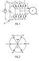
- a VSI 10 roughly consists of a DC source, to which two switches S + and S - connect in series for each of the phases RST of the output voltage to be realised, these switches being indicated by the numerals 3, 5, 7, respectively, for the S + switches and 4, 6, 8, respectively, for the S - switches.
- An electrical load in the form of a three-phase AC motor 9 is connected to the centres between the respective switches 3, 4; 5, 6 and 7, 8.
- the switches 3 - 8 are connected to a DC power supply source 1, to the output terminals of which one or more capacitors 2 are connected as an interstage circuit. Only one capacitor 2 is shown by way of example in the Figure.
- the switches 3 - 8 are IGBT- or GTO-type semiconductor switches, for example, and a diode D is connected in anti-parallel across the conducting path of each of the semiconductor switches.
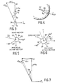
- the switching vectors are schematically shown in Figure 2 and in Table 1.
- the designations that are used refer to the vectorial addition of the voltage on the three phases R, S and T, which, as usual, are phase-shifted through 120° relative to each other.
- the six active vectors are spaced exactly 60° apart, and the zero vectors are positioned in the origin.
- the current in the three phases can be written as a vector, too.
- a motor can be represented in its simplest form by a resistor Rs and an inductor L connected in series with the internal emk u m generated by the motor and connected to the terminal voltage u * Tdq .
- the desired terminal voltage u * Tdq is composed of the voltage across the resistor R s , the voltage across the inductor L, R s i and j ⁇ L i , respectively, as well as the internal emk u m generated by the motor, which is vectorially represented by j ⁇ m , in Figure 3, wherein ⁇ is the angle frequency of the motor flux ⁇ m . It can be seen that the terminal voltage u* Tdq across the load angle ⁇ leads the realised motor current i dq in phase.
- the vector representation of the desired terminal voltage u * Tdq can be realised for a frequency convertor 10 by switching to one of the active vectors as shown in Figure 2. That is, the terminal voltage u * Tdq for realising the desired load current i * dq can be realised in steps of ⁇ 60°.
- a fairly simple switching rule can be used by switching through +60° when ⁇ ⁇ touches the outer circle, and by switching through -60° when ⁇ ⁇ comes within the inner circle. See also Table 1. If the speed of the terminal flux ⁇ * T becomes too high, the angle of ⁇ * T will lead by too much after some time, and the progression of the flux will have to be stopped. The best choice in that case is to present a zero voltage or to switch to the associated zero vector, as is indicated in Table 1. If the angle of ⁇ * T lags behind too much, a switchback to the last active vector is required. As long as no circle is touched, switching will not be necessary.
- the load angle ⁇ is generally a positive angle when the motor is driven in forward direction, whereas it is a negative angle during braking of the motor, for example, when the supply of energy is reversed.
- the load angle ⁇ may have different values, depending on the resistance R s and different dynamic situations of the motor.
- the simple switching rules as referred to above actually correspond to four different actions, viz. switching through +60°, switching through -60°, switching to the preceding active vector or switching to the nearest zero vector, so that the dead zone 20 can be effectively represented as a quadrangular area, in which the crossing of one of the boundary lines 21, 22, 23, 24 of the dead zone 20 by the terminal flux ⁇ * T will 1 initiate a specific switching action.
- the dimensions of the dead zone 20 are directly related to the allowable deviations in the terminal flux ⁇ * T , being equal to the distance between the concentric circles in Figure 4.
- the dead zone 25 which corresponds to the dead zone 20 in Figure 5, albeit transformed to the quantity to be realised, i.e. the motor current, is according to the invention oriented through the load angle ⁇ in the direction of the voltage u * T , the consequence of switching to a zero vector will be, as a result of the application of the switching rules as described above, that the resulting change in the voltage being delivered will be a "perpendicular crossing" from one boundary line 26 of the dead zone 25 to the opposite boundary line 27, as a consequence of which the number of switching actions will be effectively limited and so-called "limit cycles" will be prevented.
- the switching frequency will therefore be lower than with the known frequency convertor control.
- the voltage delivered by the frequency convertor will exhibit a pulse shape as a result of the switching of the switches. Therefore, the present description refers to effective values of voltage, current and flux.
- the dead zone When a CSI is used as the frequency convertor, the dead zone will be oriented towards the current delivered by the CSI, of course.
- the dead zone 20 or 25 does not necessarily have to be defined as a quadrangular area.
- the fact is that the shape of the dead zone is linked to the switching rules that are used, which, in the case of specific loads and specific applications, may differ from the relatively simple rules as described above.
- the size of the dead zone i.e. the dimensions thereof, also determines the switching frequency. In the case of a larger dead zone, switching will generally be required relatively less frequently than in the case of a relatively smaller dead zone, because the boundary lines of the dead zone will be crossed more rapidly in the latter case, which requires a switching action.
- the load angle ⁇ can be determined in various ways, for example from the changes in the load current or the motor current during zero vectors.
- the load angle may also be determined on the basis of the realised terminal voltage u * T . Said angle follows from the low-pass filtered values of the voltage components being transformed to the dq-domain.
- the calculation of the load angle is insufficiently accurate.
- a frequency of e.g. a few hundred Hz in the case of such small values, opposed voltage vectors are alternated with zero vectors, so that the required low voltage can be effectively realised.
- a relatively small dither signal, a triangular dither signal, for example, in the order of 1 - 2% of the voltage may be applied for rotating the dead zone.
- the dither signal may be turned off again, but it may also continue to exist.
- the dimensions of the dead zone may furthermore vary in time.
- the amplitude of the realised current will be smaller, but the angle of the realised current will continue to correspond more or less to the angle of i * dq .
- This clipping leads to a decrease in the current and thus to a significant reduction of the torque or the driving force of the motor.
- the angular displacement can be realised through integration of a signal which is proportional to the duty cycle minus a maximum desired value for the duty cycle, for example 97%. This achieves that the angle ⁇ will increase for duty cycle values above 97% and that the angle ⁇ will decrease to minimally 0% again if the duty cycle is smaller than the desired value. It is also possible, of course, to select other methods and to set other percentages in order to achieve this objective.
- the method according to the invention makes it possible to create zero vectors by suitably orienting the dead zone 20, which leads to a decreased switching frequency of the convertor, which is not possible when using a conventional hysteresis controller, for example, or only by taking more complex measures.
- the proposed orientation of the dead zone towards the voltage or current of the frequency convertor by rotating the dead zone through the load angle in the direction of the voltage or current being delivered is not limited to rotation of the dead zone exactly through the load angle ⁇ .
- Other orientations are possible, depending, among others, on the selected shape of the dead zone and the associated switching rules, it should be noted, however, that a quadrangular shape, in particular a square shape, of the dead zone and rotation through the entire load angle ⁇ will result in a very simple switching algorithm and produce excellent results.
- the method according to the invention can also be used in so-called multi-level frequency convertors, which comprises step-by-step switching of the switches for each level for the purpose of realising the quantity in question, such as the motor current in the examples as discussed above, with amplitude and phase angle deviations that remain within the limits of the dead zone.
- the associated switching vector is in turn determined by determining at what level the convertor is operative, as set forth in the foregoing.
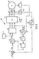
- Figure 8 shows a block diagram of an embodiment of a device 30 for carrying out the method according to the invention.
- a three-phase motor 32 is connected to the frequency convertor 31, which is of the so-called VSI type.
- the frequency convertor 31 is fed from a DC source 33.
- the frequency convertor 31 comprises a plurality of controllable switches, as discussed with reference to the frequency convertor as schematically shown in Figure 1, and control means 34 for controlling the switches for the purpose of realising a desired quantity in the motor 32, for example the motor current.
- Various sensors or estimators may be used for determining the current angle ⁇ of the rotary dq-coordinate system with respect to the stationary ⁇ -coordinate system, as represented by the block 35 and as known to those skilled in the art. From the angle ⁇ and the realised voltage u ⁇ in the fixed coordinate system of the frequency convertor 31, which can be determined from the switching vector which is imposed by the control means 34, the load angle ⁇ can be determined by rotation through the negative angle ⁇ and subsequent low-pass filtering of the thus rotated voltage, as is illustrated by the blocks 36, 37 and 38, respectively.
- the realised value of the motor current is determined by current measurement, for example by means of current transformers 39, 40, 41 and processing means 42, which value is subsequently transformed to the rotary dq-coordinate system via a rotation through - ⁇ .
- the motor current i dq thus realised is compared with the desired value of the motor current i * dq , for example via summing means 44, and the difference between the realised value and the desired value in the dq-coordinate system ⁇ i dq is supplied to a further vector rotator for rotating the deviation or the dead zone through the load angle ⁇ in accordance with the invention.
- the dimensions of the dead zone can be set in the block 47 at the input of the control means 34.
- a control programme and a data carrier such as a CD-ROM, a floppy disk or the like provided with a control programme form part of the present invention.
- the invention is not limited to the use thereof with electrical loads in the form of electric motors, such as synchronous motors or induction motors, but that the invention may also be used for realising a desired quantity in other types of electrical loads, such as transformers and load resistors having a high-frequency impedance greater than zero.
- the device and the method according to the invention are in particular suitable for controlling linear electric motors, such as linear synchronous motors or linear induction motors, in which the motor parameters are not constant. It is not necessary to know the momentary motor parameters, such as the inductance, for implementing and designing the method.
Landscapes
- Engineering & Computer Science (AREA)
- Power Engineering (AREA)
- Inverter Devices (AREA)
- Control Of Ac Motors In General (AREA)
- Ac-Ac Conversion (AREA)
Applications Claiming Priority (2)
| Application Number | Priority Date | Filing Date | Title |
|---|---|---|---|
| NL1020601A NL1020601C2 (nl) | 2002-05-15 | 2002-05-15 | Werkwijze en inrichting voor het sturen van een elektrische belasting aangesloten op een meerfasen schakelbare DC/AC-frequentie-omzetter. |
| NL1020601 | 2002-05-15 |
Publications (3)
| Publication Number | Publication Date |
|---|---|
| EP1363388A2 true EP1363388A2 (de) | 2003-11-19 |
| EP1363388A3 EP1363388A3 (de) | 2009-07-15 |
| EP1363388B1 EP1363388B1 (de) | 2018-05-30 |
Family
ID=29268072
Family Applications (1)
| Application Number | Title | Priority Date | Filing Date |
|---|---|---|---|
| EP03075753.8A Expired - Lifetime EP1363388B1 (de) | 2002-05-15 | 2003-03-17 | Verfahren und Vorrichtung zur Steuerung einer zu einem mehrphasen schaltbaren Gleichstrom-Wechselstrom-Frequenzwandler angeschlossenen elektrischen Last |
Country Status (3)
| Country | Link |
|---|---|
| US (1) | US6864660B2 (de) |
| EP (1) | EP1363388B1 (de) |
| NL (1) | NL1020601C2 (de) |
Families Citing this family (5)
| Publication number | Priority date | Publication date | Assignee | Title |
|---|---|---|---|---|
| CA2379732A1 (en) * | 2002-04-02 | 2003-10-02 | Turbocor Inc. | System and method for controlling an electric motor |
| CN100417004C (zh) * | 2003-07-23 | 2008-09-03 | 松下电器产业株式会社 | 电动机控制设备及使用其的洗衣机和干燥机 |
| FI116337B (fi) * | 2003-12-19 | 2005-10-31 | Abb Oy | Menetelmä taajuusmuuttajan lähdön virtojen määrittämiseksi |
| US7187155B2 (en) * | 2004-05-14 | 2007-03-06 | Rockwell Automation Technologies, Inc. | Leakage inductance saturation compensation for a slip control technique of a motor drive |
| US7733677B2 (en) | 2007-10-11 | 2010-06-08 | Honeywell International Inc. | Output power switching vector scaling system and method |
Family Cites Families (8)
| Publication number | Priority date | Publication date | Assignee | Title |
|---|---|---|---|---|
| GB1300226A (en) * | 1969-05-09 | 1972-12-20 | English Electric Co Ltd | Control circuits for invertors |
| DE3212439C2 (de) * | 1982-04-02 | 1992-02-20 | Robert Prof.Dr.-Ing. 6100 Darmstadt Jötten | Verfahren zum Betrieb einer durch schnelle elektrische Stellglieder gespeisten Asynchronmaschine |
| US5585709A (en) * | 1993-12-22 | 1996-12-17 | Wisconsin Alumni Research Foundation | Method and apparatus for transducerless position and velocity estimation in drives for AC machines |
| US5959430A (en) * | 1997-03-07 | 1999-09-28 | Kabushiki Kaisha Toshiba | Power conversion system |
| US6005783A (en) * | 1998-06-26 | 1999-12-21 | General Motors Corporation | Method of synthesizing poly-phase AC voltage |
| DE69901609T2 (de) * | 1999-08-18 | 2002-11-21 | Joachim Holtz | Verfahren zur Bremsung eines feldorientiertbetriebenen Asynchronmotors, Regelungsvorrichtung zur Verfahrensausführung und Speichermedium |
| US6462974B1 (en) * | 2001-09-27 | 2002-10-08 | York International Corporation | Space vector modulation-based control method and apparatus for three-phase pulse width modulated AC voltage regulators |
| US6653812B1 (en) * | 2002-01-31 | 2003-11-25 | Analog Devices, Inc. | Space vector modulation methods and structures for electric-motor control |
-
2002
- 2002-05-15 NL NL1020601A patent/NL1020601C2/nl not_active IP Right Cessation
-
2003
- 2003-03-17 EP EP03075753.8A patent/EP1363388B1/de not_active Expired - Lifetime
- 2003-05-13 US US10/437,274 patent/US6864660B2/en not_active Expired - Lifetime
Non-Patent Citations (2)
| Title |
|---|
| DOULAI P ET AL: "CO-ORDINATED THREE-PHASE HYSTERETIC-CONTROL SCHEME FOR ACTIVE POWER FILTERING" IEE PROCEEDINGS B. ELECTRICAL POWER APPLICATIONS, INSTITUTION OF ELECTRICAL ENGINEERS. STEVENAGE, GB, vol. 139, no. 5 PART B, 1 September 1992 (1992-09-01), pages 457-464, XP000320153 * |
| TRZYNADLOWSKI A M ET AL: "AN INTEGRAL SPACE-VECTOR PWM TECHNIQUE FOR DSP-CONTROLLED VOLTAGE-SOURCE INVERTERS" IEEE TRANSACTIONS ON INDUSTRY APPLICATIONS, IEEE INC. NEW YORK, US, vol. 35, no. 5, September 1999 (1999-09), pages 1091-1097, XP000924261 ISSN: 0093-9994 * |
Also Published As
| Publication number | Publication date |
|---|---|
| EP1363388B1 (de) | 2018-05-30 |
| EP1363388A3 (de) | 2009-07-15 |
| NL1020601C2 (nl) | 2003-11-27 |
| US6864660B2 (en) | 2005-03-08 |
| US20040080967A1 (en) | 2004-04-29 |
Similar Documents
| Publication | Publication Date | Title |
|---|---|---|
| TWI814727B (zh) | 多級多象限磁滯電流控制器及用於控制其之方法 | |
| WO2013105506A1 (en) | Motor Controller | |
| CN104956585B (zh) | 马达控制器 | |
| JP6168421B2 (ja) | 電力変換装置、電力変換方法、モータシステム | |
| Salah et al. | Implementation of PWM control strategy for torque ripples reduction in brushless DC motors | |
| JP6869392B1 (ja) | 交流回転電機の制御装置 | |
| US6864660B2 (en) | Method and device for controlling an electric load connected to a multiphase switchable DC/AC frequency convertor | |
| Joy et al. | Performance comparison of a sensorless PMBLDC motor drive system with conventional and fuzzy logic controllers | |
| JP6351652B2 (ja) | 電力変換器制御装置 | |
| US5109184A (en) | Direct current motor | |
| JP5181570B2 (ja) | モータ駆動装置、集積回路装置およびモータ装置 | |
| US20170279383A1 (en) | Inverter control device and inverter control method | |
| JP2023174545A (ja) | モーター相電流再構成 | |
| JP3333907B2 (ja) | 電圧形インバータの電流制限方法及び電流制限回路 | |
| JP7788943B2 (ja) | 交流回転電機の制御装置 | |
| CN113541535B (zh) | 旋转电机控制装置 | |
| JP7002626B1 (ja) | 交流回転機の制御装置 | |
| JPWO2019188876A1 (ja) | 電力変換システム、電圧変換回路の制御方法 | |
| Fuengwarodsakul et al. | Instantaneous torque controller for switched reluctance vehicle propulsion drives | |
| Yoopakdee et al. | Variable speed switched reluctance drive for low cost applications | |
| WO2025196905A1 (ja) | 交流回転電機の制御装置、交流回転電機駆動システム及び車両 | |
| JP2025129522A (ja) | 回転電機装置 | |
| WO2023199563A1 (ja) | 電力変換装置 | |
| JP2001157490A (ja) | Pwmインバータの電流制御方法およびその装置 | |
| CN119174102A (zh) | 旋转电机控制装置 |
Legal Events
| Date | Code | Title | Description |
|---|---|---|---|
| PUAI | Public reference made under article 153(3) epc to a published international application that has entered the european phase |
Free format text: ORIGINAL CODE: 0009012 |
|
| AK | Designated contracting states |
Kind code of ref document: A2 Designated state(s): AT BE BG CH CY CZ DE DK EE ES FI FR GB GR HU IE IT LI LU MC NL PT RO SE SI SK TR |
|
| AX | Request for extension of the european patent |
Extension state: AL LT LV MK |
|
| PUAL | Search report despatched |
Free format text: ORIGINAL CODE: 0009013 |
|
| AK | Designated contracting states |
Kind code of ref document: A3 Designated state(s): AT BE BG CH CY CZ DE DK EE ES FI FR GB GR HU IE IT LI LU MC NL PT RO SE SI SK TR |
|
| AX | Request for extension of the european patent |
Extension state: AL LT LV MK |
|
| 17P | Request for examination filed |
Effective date: 20100114 |
|
| AKX | Designation fees paid |
Designated state(s): AT BE BG CH CY CZ DE DK EE ES FI FR GB GR HU IE IT LI LU MC NL PT RO SE SI SK TR |
|
| STAA | Information on the status of an ep patent application or granted ep patent |
Free format text: STATUS: EXAMINATION IS IN PROGRESS |
|
| 17Q | First examination report despatched |
Effective date: 20170309 |
|
| GRAP | Despatch of communication of intention to grant a patent |
Free format text: ORIGINAL CODE: EPIDOSNIGR1 |
|
| STAA | Information on the status of an ep patent application or granted ep patent |
Free format text: STATUS: GRANT OF PATENT IS INTENDED |
|
| INTG | Intention to grant announced |
Effective date: 20171208 |
|
| GRAS | Grant fee paid |
Free format text: ORIGINAL CODE: EPIDOSNIGR3 |
|
| GRAA | (expected) grant |
Free format text: ORIGINAL CODE: 0009210 |
|
| STAA | Information on the status of an ep patent application or granted ep patent |
Free format text: STATUS: THE PATENT HAS BEEN GRANTED |
|
| AK | Designated contracting states |
Kind code of ref document: B1 Designated state(s): AT BE BG CH CY CZ DE DK EE ES FI FR GB GR HU IE IT LI LU MC NL PT RO SE SI SK TR |
|
| RAP1 | Party data changed (applicant data changed or rights of an application transferred) |
Owner name: ENGIE ELECTROPROJECT B.V. |
|
| REG | Reference to a national code |
Ref country code: GB Ref legal event code: FG4D |
|
| REG | Reference to a national code |
Ref country code: CH Ref legal event code: EP |
|
| REG | Reference to a national code |
Ref country code: AT Ref legal event code: REF Ref document number: 1004627 Country of ref document: AT Kind code of ref document: T Effective date: 20180615 |
|
| REG | Reference to a national code |
Ref country code: DE Ref legal event code: R096 Ref document number: 60351218 Country of ref document: DE |
|
| REG | Reference to a national code |
Ref country code: IE Ref legal event code: FG4D |
|
| REG | Reference to a national code |
Ref country code: CH Ref legal event code: NV Representative=s name: CABINET GERMAIN AND MAUREAU, CH |
|
| REG | Reference to a national code |
Ref country code: NL Ref legal event code: FP |
|
| PG25 | Lapsed in a contracting state [announced via postgrant information from national office to epo] |
Ref country code: BG Free format text: LAPSE BECAUSE OF FAILURE TO SUBMIT A TRANSLATION OF THE DESCRIPTION OR TO PAY THE FEE WITHIN THE PRESCRIBED TIME-LIMIT Effective date: 20180830 Ref country code: FI Free format text: LAPSE BECAUSE OF FAILURE TO SUBMIT A TRANSLATION OF THE DESCRIPTION OR TO PAY THE FEE WITHIN THE PRESCRIBED TIME-LIMIT Effective date: 20180530 Ref country code: ES Free format text: LAPSE BECAUSE OF FAILURE TO SUBMIT A TRANSLATION OF THE DESCRIPTION OR TO PAY THE FEE WITHIN THE PRESCRIBED TIME-LIMIT Effective date: 20180530 Ref country code: SE Free format text: LAPSE BECAUSE OF FAILURE TO SUBMIT A TRANSLATION OF THE DESCRIPTION OR TO PAY THE FEE WITHIN THE PRESCRIBED TIME-LIMIT Effective date: 20180530 Ref country code: CY Free format text: LAPSE BECAUSE OF FAILURE TO SUBMIT A TRANSLATION OF THE DESCRIPTION OR TO PAY THE FEE WITHIN THE PRESCRIBED TIME-LIMIT Effective date: 20180530 |
|
| PG25 | Lapsed in a contracting state [announced via postgrant information from national office to epo] |
Ref country code: GR Free format text: LAPSE BECAUSE OF FAILURE TO SUBMIT A TRANSLATION OF THE DESCRIPTION OR TO PAY THE FEE WITHIN THE PRESCRIBED TIME-LIMIT Effective date: 20180831 |
|
| REG | Reference to a national code |
Ref country code: AT Ref legal event code: MK05 Ref document number: 1004627 Country of ref document: AT Kind code of ref document: T Effective date: 20180530 |
|
| PG25 | Lapsed in a contracting state [announced via postgrant information from national office to epo] |
Ref country code: DK Free format text: LAPSE BECAUSE OF FAILURE TO SUBMIT A TRANSLATION OF THE DESCRIPTION OR TO PAY THE FEE WITHIN THE PRESCRIBED TIME-LIMIT Effective date: 20180530 Ref country code: AT Free format text: LAPSE BECAUSE OF FAILURE TO SUBMIT A TRANSLATION OF THE DESCRIPTION OR TO PAY THE FEE WITHIN THE PRESCRIBED TIME-LIMIT Effective date: 20180530 Ref country code: EE Free format text: LAPSE BECAUSE OF FAILURE TO SUBMIT A TRANSLATION OF THE DESCRIPTION OR TO PAY THE FEE WITHIN THE PRESCRIBED TIME-LIMIT Effective date: 20180530 Ref country code: SK Free format text: LAPSE BECAUSE OF FAILURE TO SUBMIT A TRANSLATION OF THE DESCRIPTION OR TO PAY THE FEE WITHIN THE PRESCRIBED TIME-LIMIT Effective date: 20180530 Ref country code: RO Free format text: LAPSE BECAUSE OF FAILURE TO SUBMIT A TRANSLATION OF THE DESCRIPTION OR TO PAY THE FEE WITHIN THE PRESCRIBED TIME-LIMIT Effective date: 20180530 Ref country code: CZ Free format text: LAPSE BECAUSE OF FAILURE TO SUBMIT A TRANSLATION OF THE DESCRIPTION OR TO PAY THE FEE WITHIN THE PRESCRIBED TIME-LIMIT Effective date: 20180530 |
|
| PG25 | Lapsed in a contracting state [announced via postgrant information from national office to epo] |
Ref country code: IT Free format text: LAPSE BECAUSE OF FAILURE TO SUBMIT A TRANSLATION OF THE DESCRIPTION OR TO PAY THE FEE WITHIN THE PRESCRIBED TIME-LIMIT Effective date: 20180530 |
|
| REG | Reference to a national code |
Ref country code: DE Ref legal event code: R097 Ref document number: 60351218 Country of ref document: DE |
|
| PLBE | No opposition filed within time limit |
Free format text: ORIGINAL CODE: 0009261 |
|
| STAA | Information on the status of an ep patent application or granted ep patent |
Free format text: STATUS: NO OPPOSITION FILED WITHIN TIME LIMIT |
|
| 26N | No opposition filed |
Effective date: 20190301 |
|
| PG25 | Lapsed in a contracting state [announced via postgrant information from national office to epo] |
Ref country code: SI Free format text: LAPSE BECAUSE OF FAILURE TO SUBMIT A TRANSLATION OF THE DESCRIPTION OR TO PAY THE FEE WITHIN THE PRESCRIBED TIME-LIMIT Effective date: 20180530 |
|
| PG25 | Lapsed in a contracting state [announced via postgrant information from national office to epo] |
Ref country code: MC Free format text: LAPSE BECAUSE OF FAILURE TO SUBMIT A TRANSLATION OF THE DESCRIPTION OR TO PAY THE FEE WITHIN THE PRESCRIBED TIME-LIMIT Effective date: 20180530 |
|
| PG25 | Lapsed in a contracting state [announced via postgrant information from national office to epo] |
Ref country code: LU Free format text: LAPSE BECAUSE OF NON-PAYMENT OF DUE FEES Effective date: 20190317 |
|
| REG | Reference to a national code |
Ref country code: BE Ref legal event code: MM Effective date: 20190331 |
|
| PG25 | Lapsed in a contracting state [announced via postgrant information from national office to epo] |
Ref country code: IE Free format text: LAPSE BECAUSE OF NON-PAYMENT OF DUE FEES Effective date: 20190317 |
|
| PG25 | Lapsed in a contracting state [announced via postgrant information from national office to epo] |
Ref country code: BE Free format text: LAPSE BECAUSE OF NON-PAYMENT OF DUE FEES Effective date: 20190331 |
|
| PG25 | Lapsed in a contracting state [announced via postgrant information from national office to epo] |
Ref country code: TR Free format text: LAPSE BECAUSE OF FAILURE TO SUBMIT A TRANSLATION OF THE DESCRIPTION OR TO PAY THE FEE WITHIN THE PRESCRIBED TIME-LIMIT Effective date: 20180530 |
|
| PG25 | Lapsed in a contracting state [announced via postgrant information from national office to epo] |
Ref country code: PT Free format text: LAPSE BECAUSE OF FAILURE TO SUBMIT A TRANSLATION OF THE DESCRIPTION OR TO PAY THE FEE WITHIN THE PRESCRIBED TIME-LIMIT Effective date: 20181001 |
|
| PG25 | Lapsed in a contracting state [announced via postgrant information from national office to epo] |
Ref country code: HU Free format text: LAPSE BECAUSE OF FAILURE TO SUBMIT A TRANSLATION OF THE DESCRIPTION OR TO PAY THE FEE WITHIN THE PRESCRIBED TIME-LIMIT; INVALID AB INITIO Effective date: 20030317 |
|
| PGFP | Annual fee paid to national office [announced via postgrant information from national office to epo] |
Ref country code: GB Payment date: 20220321 Year of fee payment: 20 Ref country code: DE Payment date: 20220322 Year of fee payment: 20 Ref country code: CH Payment date: 20220321 Year of fee payment: 20 |
|
| PGFP | Annual fee paid to national office [announced via postgrant information from national office to epo] |
Ref country code: NL Payment date: 20220321 Year of fee payment: 20 Ref country code: FR Payment date: 20220322 Year of fee payment: 20 |
|
| REG | Reference to a national code |
Ref country code: DE Ref legal event code: R071 Ref document number: 60351218 Country of ref document: DE |
|
| REG | Reference to a national code |
Ref country code: NL Ref legal event code: MK Effective date: 20230316 |
|
| REG | Reference to a national code |
Ref country code: CH Ref legal event code: PL |
|
| REG | Reference to a national code |
Ref country code: GB Ref legal event code: PE20 Expiry date: 20230316 |
|
| PG25 | Lapsed in a contracting state [announced via postgrant information from national office to epo] |
Ref country code: GB Free format text: LAPSE BECAUSE OF EXPIRATION OF PROTECTION Effective date: 20230316 |