EP1362945A2 - Niederhalter zum Nähen von Matratzenetiketten - Google Patents
Niederhalter zum Nähen von Matratzenetiketten Download PDFInfo
- Publication number
- EP1362945A2 EP1362945A2 EP03252733A EP03252733A EP1362945A2 EP 1362945 A2 EP1362945 A2 EP 1362945A2 EP 03252733 A EP03252733 A EP 03252733A EP 03252733 A EP03252733 A EP 03252733A EP 1362945 A2 EP1362945 A2 EP 1362945A2
- Authority
- EP
- European Patent Office
- Prior art keywords
- movable
- movable member
- clamp
- opening
- frame
- Prior art date
- Legal status (The legal status is an assumption and is not a legal conclusion. Google has not performed a legal analysis and makes no representation as to the accuracy of the status listed.)
- Granted
Links
- 238000009958 sewing Methods 0.000 title claims abstract description 52
- 239000000463 material Substances 0.000 claims abstract description 43
- 238000000034 method Methods 0.000 claims description 19
- 230000004044 response Effects 0.000 claims description 3
- 230000001419 dependent effect Effects 0.000 claims 1
- 230000002452 interceptive effect Effects 0.000 claims 1
- 230000008569 process Effects 0.000 description 4
- 230000008859 change Effects 0.000 description 3
- 238000004519 manufacturing process Methods 0.000 description 3
- 229920000271 Kevlar® Polymers 0.000 description 1
- 239000002131 composite material Substances 0.000 description 1
- -1 for example Substances 0.000 description 1
- 239000004761 kevlar Substances 0.000 description 1
- 239000010985 leather Substances 0.000 description 1
- 230000007246 mechanism Effects 0.000 description 1
- 230000003340 mental effect Effects 0.000 description 1
- 238000012986 modification Methods 0.000 description 1
- 230000004048 modification Effects 0.000 description 1
- 230000000284 resting effect Effects 0.000 description 1
Images

Classifications
-
- D—TEXTILES; PAPER
- D05—SEWING; EMBROIDERING; TUFTING
- D05B—SEWING
- D05B3/00—Sewing apparatus or machines with mechanism for lateral movement of the needle or the work or both for making ornamental pattern seams, for sewing buttonholes, for reinforcing openings, or for fastening articles, e.g. buttons, by sewing
- D05B3/12—Sewing apparatus or machines with mechanism for lateral movement of the needle or the work or both for making ornamental pattern seams, for sewing buttonholes, for reinforcing openings, or for fastening articles, e.g. buttons, by sewing for fastening articles by sewing
- D05B3/20—Sewing apparatus or machines with mechanism for lateral movement of the needle or the work or both for making ornamental pattern seams, for sewing buttonholes, for reinforcing openings, or for fastening articles, e.g. buttons, by sewing for fastening articles by sewing labels
-
- B—PERFORMING OPERATIONS; TRANSPORTING
- B25—HAND TOOLS; PORTABLE POWER-DRIVEN TOOLS; MANIPULATORS
- B25B—TOOLS OR BENCH DEVICES NOT OTHERWISE PROVIDED FOR, FOR FASTENING, CONNECTING, DISENGAGING OR HOLDING
- B25B5/00—Clamps
- B25B5/06—Arrangements for positively actuating jaws
- B25B5/08—Arrangements for positively actuating jaws using cams
- B25B5/087—Arrangements for positively actuating jaws using cams actuated by a hydraulic or pneumatic piston
-
- D—TEXTILES; PAPER
- D05—SEWING; EMBROIDERING; TUFTING
- D05B—SEWING
- D05B35/00—Work-feeding or -handling elements not otherwise provided for
- D05B35/06—Work-feeding or -handling elements not otherwise provided for for attaching bands, ribbons, strips, or tapes or for binding
-
- D—TEXTILES; PAPER
- D05—SEWING; EMBROIDERING; TUFTING
- D05C—EMBROIDERING; TUFTING
- D05C9/00—Appliances for holding or feeding the base fabric in embroidering machines
- D05C9/02—Appliances for holding or feeding the base fabric in embroidering machines in machines with vertical needles
- D05C9/04—Work holders, e.g. frames
-
- D—TEXTILES; PAPER
- D05—SEWING; EMBROIDERING; TUFTING
- D05B—SEWING
- D05B11/00—Machines for sewing quilts or mattresses
Definitions
- This invention relates generally to sewing machines and more particularly, to a method and apparatus for holding a mattress label while it is being sewn to a mattress panel.
- identifying labels are preferably made of a high quality material and attached to the product in a high quality manner.
- mattress companies have specifications regarding the appearance and the attachment of the label. Among these is the requirement that the outer edge of the label must be securely sewn to a top panel of the mattress.
- the label should not have trim tails or other unsightly features.
- the invention provides a clamping system for a sewing machine.
- the sewing machine has a frame and an opening in the frame for receiving a first material that is to be sewn with the sewing machine to a second material.
- the clamping system has a plurality of clamps mounted adjacent the opening in the frame.
- Each of the clamps has a stationary member, a movable member and an actuator.
- the actuator is connected to the movable member and operates to move the movable member in a clamping relationship with the stationary member to clamp the first material in the clamp.
- the clamp is powered by a cylinder with a linear stroke and the clamp has a driving member that transfers the linear motion of the cylinder into a pivoting motion of the movable member.
- the movable and fixed members have forward ends shaped so that they hold the first material but do not interfere with a sewing of the first material to the second material.
- a method of securing a stitchable material in a sewing machine having a frame and an opening in the frame for receiving the stitchable material.
- an edge of the stitchable material is located between a movable member and a fixed member of a clamp mounted adjacent the opening.
- the movable member is moved toward the stationary member to clamp the edge of the stitchable material between the movable and the stationary members.
- a driving member is translated by an actuator and raises a rearward end of the movable member, thereby pivoting a forward end of the movable member against a forward end of the stationary member.
- the preferred clamping system reliably secures the mattress label while it is being sewn on a mattress panel.
- the clamping system is easier to use and therefore, leads to a faster and ore reliable placement of the mattress label in the sewing machine.
- the clamping system is especially useful in a production environment where its ease of use and reliability help to substantially relieve sewing machine operator stress in the process of sewing a label to a product. Further, the clamping system substantially reduces rework or resewing of a label and therefore, provides a more efficient cost effective label sewing operation.
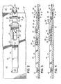
- a sewing system 20 includes a frame 22 mounted on a base plate 24.
- the base plate 24 and a pivotable panel clamp 28 are movable in mutually perpendicular X and Y directions with respect to a base 27 in a known manner.
- a sewing machine 30 has a needle 34, a presser foot 36, a bobbin (not shown) and actuators (not shown) for moving the base plate 24 and panel clamp 28 in response to command signals from a sewing machine controller 38 in a known manner.
- the sewing machine 30 is an electronically programmable X-Y sewing machine that, in one embodiment, utilizes a Mitsubishi No. PLK A 4516 sewing machine.
- the sewing machine 30 performs lock-stitching and may be programmed to implement different styles of lock-stitching, for example, a zig-zag stitch of 7.5 millimeters.
- Lock-stitching is a known technique of interlacing a needle thread and bobbin thread, which will not be described here further except to indicate that a needle thread is carried by needle 34 and a bobbin thread provided by a bobbin (not shown).
- the operation of the sewing machine 30 is controlled by user operating I/O devices 37 on a front panel of the controller 38.
- the controller 38 receives inputs from devices, for example, a main shaft encoder, and provides command signals to a sewing head motor (not shown) and actuators (not shown) to implement a stitch pattern in a known manner.
- the controller 38 also provides command signals to perform other operations, for example, raise and lower the presser foot 36, raise and lower the panel clamp 28, etc.
- the command signals are received by solenoids (not shown) that, in turn, change the states of pneumatic logic, which supply pressurized air to various pneumatic components in a known manner.
- the sewing machine 30 is illustrated with the panel clamp 28 in its raised position.
- the label frame 22 and base plate 24 have respective openings 40 in which a mattress label 42 can be located.
- a label clamping system 44 is used to hold the mattress label 42 within the opening 40.
- the label clamping system 44 is comprised of four clamps 46 mounted on the label frame 22. Each of the clamps is identical in its structure and operation.
- a clamp 46 has an actuator 50, for example, a pneumatic cylinder, mounted to an upper side of the frame 22 by fasteners 48 or other means.
- the actuator 50 has an actuator shaft or rod 52, for example, a cylinder rod, extending from a forward end.
- the actuator rod 52 extends and retracts or translates through a linear motion in response to the actuator 50 being operated between its two states.
- the actuator rod 52 is connected to a rearward end of a toggle driver 54 by a pin or other fastener 56.
- the toggle driver 54 has a slot 58 that receives a guide pin 60, for example, a screw or other fastener.
- the slot 58 and guide pin 60 function with the actuator rod 52 to facilitate a translation or linear motion of the toggle driver 54.
- a movable pivot clip or member 64 is pivotally mounted on the frame 22 with a pivot pin 66 that is located in a groove 68 and secured by pin clamps 70. As shown in Fig. 3, the pivot clip 64 is mounted in a slot 72 located in an upper surface of the frame 22.
- a fixed or stationary clip 74 is mounted by fasteners (not shown) in a slot 76 located in a lower surface of the label frame 22.
- the forward end 78 of the movable clip 64 and the forward end 80 of the fixed clip 74 extend over an opening edge 81 and into the opening 40 in the label frame 22.
- the forward ends 78, 80 of the respective clips 64, 74 have a shape that is effective to secure the label 42 therebetween but does not interfere with the sewing machine sewing around a perimeter of the label 42.
- the forward ends 78, 80 of each of the respective clips 64, 74 terminate with a pair of small pointed tips 82 that are separated by a V-shaped cutout 84.
- the forward end of the toggle driver 54 has an angled or inclined surface 62 that receives a rearward end 86 of the pivot clip 64.
- the actuator 50 When the actuator 50 is in a first state in which the actuator rod 52 is fully retracted, the rearward end 86 of the pivot clip 64 is located at a lower end of the inclined surface 62, thereby placing the forward end 78 of the pivot clip 64 in a raised position.
- a user generated command signal from the controller 38 changes a state of an actuator solenoid (not shown) that, in turn, changes a flow of pressurized air to the actuator 50, thereby changing its state. Changing the state of the actuator 50 extends the actuator rod 52 and moves the toggle driver 54 forward, that is, from left to right as viewed in Fig. 3.
- a user operates appropriate I/O devices 37 on the controller 38 to move the base plate 24 to a desired starting location and then to raise panel clamp 28 in a known manner. Thereafter, the user disposes a label 42 face-side down in the opening 40 and locates edges of the label 42 on the forward ends 80 (Fig. 3) of respective stationary clips 74. When the label edges are located on the stationary clips 74 to the user's satisfaction, the user operates appropriate I/O devices 37 on the controller 38 to command a change of state of all of the actuators 50 (Fig. 3) of all respective clamps 46. The actuators 50 simultaneously extend respective actuator rods 52 and move respective toggle drivers 54 forward.
- the user then places a mattress panel (not shown) over the clamped label 42.
- the user again activates appropriate I/O devices 37 on the controller 38 to lower the panel clamp 28.
- the panel clamp 28 secures the mattress panel against the frame 22 in a desired position relative to the clamped label 42 in a known manner.
- the user then operates the sewing machine 30 so that the label is sewn to the mattress panel with a lock-stitch along an edge of the label.
- the pointed profiles of the forward ends 78, 80 of the respective pivot and stationary clips 64, 74 permit the label edge to be satisfactorily secured and also allow a zig-zag stitch or the like to proceed down a label edge without interference from the clamps 46.
- the user again operates appropriate I/O devices 37 on the controller 38 to raise the panel clamp 28.
- the user operates appropriate I/O devices 37 to command a change of state of all of the actuators 50 (Fig. 3) of the respective clamps 46.
- the actuators 50 simultaneously retract respective actuator rods 52 and move respective toggle drivers 54 rearward.
- the mattress panel is resting on top of the forward ends 78 of the pivot clips 64; and therefore, the rearward ends 86 remain elevated after the respective toggle drivers 54 have been retracted.
- the user then lifts the mattress panel and sewn label off of the sewing apparatus 20.
- the mattress label 42 is between the pivot clips 64 and respective stationary clips 74; and as the mattress label 42 is raised from the frame 22, it raises the forward ends 78 of respective pivot clips 64.
- the rearward ends 86 of the respective pivot clips 64 drop down onto lower ends of respective inclined surfaces 62, and all of the clamps 46 are open ready to receive another mattress label.
- the above-described clamping system 44 reliably secures a label while it is being sewn to a mattress panel.
- the clamping system 44 is easy to use and therefore, leads to a faster and more reliable placement of the mattress label in the label frame 22 of the sewing machine 30.
- the clamping system 44 is especially useful in a production environment where its ease of use and reliability help to substantially relieve sewing machine operator stress in the process of sewing a label 42 to a product. Further, the clamping system 44 substantially reduces rework or resewing of a label and therefore, provides a more efficient and cost effective label sewing operation.
- clamps 46 are mounted as two opposed pairs of clamps on opposite lateral sides of the frame 22.
- the clamps 46 may be arranged in other configurations around the perimeter of the frame 22, for example, one clamp can be mounted on each of the four sides of the frame 22 or the two pairs of clamps may be mounted on opposed upper and lower sides of the frame 22.
- the sewing system 20 is used to sew a label onto a mattress panel; however, as will be appreciated, the sewing system 20 can be used to sew other stitchable materials, for example, leather, a "KEVLAR" composite material, etc. Therefore, in other embodiments, the number of clamps 46 used can be changed to meet the needs of a particular application, for example, depending on the stiffness of the materials being sewn, a greater number or a fewer number of clamps 46 may be used. Further, in the described embodiment, the clamp actuator 50 is described as being pneumatically operated; however as will be appreciated, in other embodiments, the clamp actuator 50 may be electrically operated.
- the pivot clip 64 is opened by the act of the sewn mattress panel and label being removed from the sewing system 20.
- a positive opening force can also be applied to the pivot member 64, for example, a torsion spring can be mounted over the pivot pin 66 and used to apply a biasing force to help move the pivot clip rearward end 86 down the inclined surface 62.
- the toggle driver 54 can be replaced by other mechanisms for operatively connecting the actuator 46 to the pivot clip 64.
Landscapes
- Engineering & Computer Science (AREA)
- Textile Engineering (AREA)
- Mechanical Engineering (AREA)
- Sewing Machines And Sewing (AREA)
Applications Claiming Priority (2)
| Application Number | Priority Date | Filing Date | Title |
|---|---|---|---|
| US147638 | 2002-05-17 | ||
| US10/147,638 US6662737B2 (en) | 2002-05-17 | 2002-05-17 | Mattress label sewing clamp |
Publications (3)
| Publication Number | Publication Date |
|---|---|
| EP1362945A2 true EP1362945A2 (de) | 2003-11-19 |
| EP1362945A3 EP1362945A3 (de) | 2005-02-09 |
| EP1362945B1 EP1362945B1 (de) | 2017-12-27 |
Family
ID=29269769
Family Applications (1)
| Application Number | Title | Priority Date | Filing Date |
|---|---|---|---|
| EP03252733.5A Expired - Lifetime EP1362945B1 (de) | 2002-05-17 | 2003-04-30 | Niederhalter zum Nähen von Matratzenetiketten |
Country Status (2)
| Country | Link |
|---|---|
| US (1) | US6662737B2 (de) |
| EP (1) | EP1362945B1 (de) |
Cited By (3)
| Publication number | Priority date | Publication date | Assignee | Title |
|---|---|---|---|---|
| CN101173431B (zh) * | 2006-11-03 | 2011-06-08 | 日星特殊精密株式会社 | 齿条-小齿轮式动力传递装置以及具有该装置的用于驱动绣花机的绣花架的设备 |
| CN106319789A (zh) * | 2016-06-28 | 2017-01-11 | 诸暨创加电子设备有限公司 | 一种绣花机、工装及装配方法 |
| CN106319792A (zh) * | 2016-06-23 | 2017-01-11 | 诸暨创加电子设备有限公司 | 一种机头定位机构及安装方法 |
Families Citing this family (5)
| Publication number | Priority date | Publication date | Assignee | Title |
|---|---|---|---|---|
| US7100526B1 (en) | 2004-09-27 | 2006-09-05 | Atlanta Attachment Company, Inc. | Label/tag inserter system |
| US8739716B2 (en) * | 2010-02-23 | 2014-06-03 | Atlanta Attachment Company | Automated quilting and tufting system |
| CN104233648B (zh) * | 2014-09-17 | 2017-02-22 | 东莞市迈特运动用品有限公司 | 一种手套织标车缝治具及手套织标车缝方法 |
| CN106120182A (zh) * | 2016-08-22 | 2016-11-16 | 际华三五三实业有限公司 | 一种缝接商标的模具及方法 |
| CN110877196B (zh) * | 2019-12-08 | 2021-08-06 | 湖南凯斯机械股份有限公司 | 一种提高缝纫机机头加工效率的加工工艺 |
Citations (3)
| Publication number | Priority date | Publication date | Assignee | Title |
|---|---|---|---|---|
| US3482536A (en) | 1967-08-22 | 1969-12-09 | Mas Fab Carl Zangs | Fast tenter frame for multi-head embroidering machines |
| US5520129A (en) | 1994-03-17 | 1996-05-28 | Porter Sewing Machines, Inc. | Method and apparatus for join and sew application |
| US5595375A (en) | 1995-05-12 | 1997-01-21 | Benn Corporation | Self-tightening, easily releasable clamping device capable of being retained in an open position |
Family Cites Families (7)
| Publication number | Priority date | Publication date | Assignee | Title |
|---|---|---|---|---|
| US3044426A (en) * | 1960-03-23 | 1962-07-17 | Schwarzberger Arthur | Work-handling apparatus for quilting machines |
| CH429397A (fr) * | 1965-01-25 | 1967-01-31 | Luxar S A R L | Procédé pour garnir un cadre au moyen d'une toile tendue et dispositif pour la mise en oeuvre de ce procédé |
| US3724836A (en) | 1971-07-12 | 1973-04-03 | Dover Corp | Power operated swing clamp |
| IT1159279B (it) | 1982-05-17 | 1987-02-25 | Necchi Spa | Apparecchiatura automatica per l'esecuzione di cuciture secondo un profilo determinato |
| DE4437503A1 (de) * | 1993-10-27 | 1995-05-04 | Schweiz Seidengazefabrik Ag Th | Vorrichtung zum Aufspannen eines Gewebestückes |
| US6065412A (en) | 1997-02-25 | 2000-05-23 | Schwarzberger; Michael V. | Vertical stitching machine and method |
| US6123042A (en) * | 1999-04-09 | 2000-09-26 | Durkopp Adler Aktiengesellschaft | Automatic sewing machine |
-
2002
- 2002-05-17 US US10/147,638 patent/US6662737B2/en not_active Expired - Lifetime
-
2003
- 2003-04-30 EP EP03252733.5A patent/EP1362945B1/de not_active Expired - Lifetime
Patent Citations (3)
| Publication number | Priority date | Publication date | Assignee | Title |
|---|---|---|---|---|
| US3482536A (en) | 1967-08-22 | 1969-12-09 | Mas Fab Carl Zangs | Fast tenter frame for multi-head embroidering machines |
| US5520129A (en) | 1994-03-17 | 1996-05-28 | Porter Sewing Machines, Inc. | Method and apparatus for join and sew application |
| US5595375A (en) | 1995-05-12 | 1997-01-21 | Benn Corporation | Self-tightening, easily releasable clamping device capable of being retained in an open position |
Cited By (4)
| Publication number | Priority date | Publication date | Assignee | Title |
|---|---|---|---|---|
| CN101173431B (zh) * | 2006-11-03 | 2011-06-08 | 日星特殊精密株式会社 | 齿条-小齿轮式动力传递装置以及具有该装置的用于驱动绣花机的绣花架的设备 |
| CN106319792A (zh) * | 2016-06-23 | 2017-01-11 | 诸暨创加电子设备有限公司 | 一种机头定位机构及安装方法 |
| CN106319792B (zh) * | 2016-06-23 | 2019-12-17 | 诸暨创加电子设备有限公司 | 一种机头定位机构及安装方法 |
| CN106319789A (zh) * | 2016-06-28 | 2017-01-11 | 诸暨创加电子设备有限公司 | 一种绣花机、工装及装配方法 |
Also Published As
| Publication number | Publication date |
|---|---|
| EP1362945A3 (de) | 2005-02-09 |
| US20030213418A1 (en) | 2003-11-20 |
| US6662737B2 (en) | 2003-12-16 |
| EP1362945B1 (de) | 2017-12-27 |
Similar Documents
| Publication | Publication Date | Title |
|---|---|---|
| US5927221A (en) | Method and apparatus for join and sew application | |
| CN107304496A (zh) | 缝纫机 | |
| US4854251A (en) | Automatic sewing machine exclusively used for sewing zipper on workpiece | |
| US6662737B2 (en) | Mattress label sewing clamp | |
| US5553564A (en) | Automatic sewing machine system and method for loading and sewing workpieces | |
| US4870917A (en) | Work holder for sewing machines | |
| JP2025528593A (ja) | 刺繍機のための布の固定枠部材及び枠部材を備える刺繍機 | |
| CN106245239B (zh) | 夹紧机构及具备该夹紧机构的缝纫机 | |
| US5931108A (en) | Process and automatic sewing machine for sewing a flap with a rough closing edge and a pocket on a fabric part in one operation | |
| US5094179A (en) | Attachable label sewing apparatus | |
| US5109785A (en) | Workpiece fabric feeding device for binder strip sewing machine | |
| JP4409049B2 (ja) | 穴かがりミシンの布開き装置 | |
| US4589359A (en) | Workpiece receiving device for a sewing machine, in particular for a computer-controlled automatic sewing device | |
| US4648335A (en) | Apparatus for setting a workpiece correctly on a sewing machine | |
| US20030192463A1 (en) | Buttonhole sewing machine | |
| US4892049A (en) | Automatic sewing machine exclusively used for sewing zipper on workpiece | |
| US4898109A (en) | Device for sewing a collar on to a body of an article of clothing | |
| CN105506867B (zh) | 缝纫机 | |
| KR101162366B1 (ko) | 아이형 단추구멍 재봉기 | |
| JPH10314473A (ja) | 被加工物にフラップを縫い付けるための自動裁縫装置 | |
| US5609115A (en) | Buttonhole closing device for lockstitch bar tacking sewing machine | |
| JPH0358756B2 (de) | ||
| US5598801A (en) | Easy loading sewing station | |
| JP2520868B2 (ja) | ジツパ−縫付専用自動ミシン | |
| JPH06134153A (ja) | 地衿八刺し自動縫製機 |
Legal Events
| Date | Code | Title | Description |
|---|---|---|---|
| PUAI | Public reference made under article 153(3) epc to a published international application that has entered the european phase |
Free format text: ORIGINAL CODE: 0009012 |
|
| AK | Designated contracting states |
Kind code of ref document: A2 Designated state(s): AT BE BG CH CY CZ DE DK EE ES FI FR GB GR HU IE IT LI LU MC NL PT RO SE SI SK TR |
|
| AX | Request for extension of the european patent |
Extension state: AL LT LV MK |
|
| PUAL | Search report despatched |
Free format text: ORIGINAL CODE: 0009013 |
|
| AK | Designated contracting states |
Kind code of ref document: A3 Designated state(s): AT BE BG CH CY CZ DE DK EE ES FI FR GB GR HU IE IT LI LU MC NL PT RO SE SI SK TR |
|
| AX | Request for extension of the european patent |
Extension state: AL LT LV MK |
|
| 17P | Request for examination filed |
Effective date: 20050322 |
|
| AKX | Designation fees paid |
Designated state(s): ES GB IT |
|
| REG | Reference to a national code |
Ref country code: DE Ref legal event code: 8566 |
|
| 17Q | First examination report despatched |
Effective date: 20081215 |
|
| RIC1 | Information provided on ipc code assigned before grant |
Ipc: D05B 35/06 20060101ALI20170531BHEP Ipc: D05B 39/00 20060101ALI20170531BHEP Ipc: D05B 11/00 20060101ALN20170531BHEP Ipc: D05C 9/04 20060101AFI20170531BHEP Ipc: D05B 3/20 20060101ALI20170531BHEP |
|
| GRAP | Despatch of communication of intention to grant a patent |
Free format text: ORIGINAL CODE: EPIDOSNIGR1 |
|
| INTG | Intention to grant announced |
Effective date: 20170720 |
|
| GRAS | Grant fee paid |
Free format text: ORIGINAL CODE: EPIDOSNIGR3 |
|
| GRAA | (expected) grant |
Free format text: ORIGINAL CODE: 0009210 |
|
| AK | Designated contracting states |
Kind code of ref document: B1 Designated state(s): ES GB IT |
|
| REG | Reference to a national code |
Ref country code: GB Ref legal event code: FG4D |
|
| PG25 | Lapsed in a contracting state [announced via postgrant information from national office to epo] |
Ref country code: ES Free format text: LAPSE BECAUSE OF FAILURE TO SUBMIT A TRANSLATION OF THE DESCRIPTION OR TO PAY THE FEE WITHIN THE PRESCRIBED TIME-LIMIT Effective date: 20171227 |
|
| PLBE | No opposition filed within time limit |
Free format text: ORIGINAL CODE: 0009261 |
|
| STAA | Information on the status of an ep patent application or granted ep patent |
Free format text: STATUS: NO OPPOSITION FILED WITHIN TIME LIMIT |
|
| 26N | No opposition filed |
Effective date: 20180928 |
|
| GBPC | Gb: european patent ceased through non-payment of renewal fee |
Effective date: 20180430 |
|
| PG25 | Lapsed in a contracting state [announced via postgrant information from national office to epo] |
Ref country code: GB Free format text: LAPSE BECAUSE OF NON-PAYMENT OF DUE FEES Effective date: 20180430 |
|
| PGFP | Annual fee paid to national office [announced via postgrant information from national office to epo] |
Ref country code: IT Payment date: 20200312 Year of fee payment: 18 |
|
| PG25 | Lapsed in a contracting state [announced via postgrant information from national office to epo] |
Ref country code: IT Free format text: LAPSE BECAUSE OF NON-PAYMENT OF DUE FEES Effective date: 20200430 |