EP1362829A1 - Générateur d'ozone - Google Patents
Générateur d'ozone Download PDFInfo
- Publication number
- EP1362829A1 EP1362829A1 EP03008683A EP03008683A EP1362829A1 EP 1362829 A1 EP1362829 A1 EP 1362829A1 EP 03008683 A EP03008683 A EP 03008683A EP 03008683 A EP03008683 A EP 03008683A EP 1362829 A1 EP1362829 A1 EP 1362829A1
- Authority
- EP
- European Patent Office
- Prior art keywords
- ozone generating
- generating elements
- ozone
- process water
- generator according
- Prior art date
- Legal status (The legal status is an assumption and is not a legal conclusion. Google has not performed a legal analysis and makes no representation as to the accuracy of the status listed.)
- Granted
Links
- CBENFWSGALASAD-UHFFFAOYSA-N Ozone Chemical compound [O-][O+]=O CBENFWSGALASAD-UHFFFAOYSA-N 0.000 title claims abstract description 133
- 238000000034 method Methods 0.000 claims abstract description 41
- XLYOFNOQVPJJNP-UHFFFAOYSA-N water Substances O XLYOFNOQVPJJNP-UHFFFAOYSA-N 0.000 claims abstract description 39
- 229910001220 stainless steel Inorganic materials 0.000 claims description 6
- 239000010935 stainless steel Substances 0.000 claims description 6
- 238000001816 cooling Methods 0.000 description 12
- 239000007789 gas Substances 0.000 description 8
- 239000011521 glass Substances 0.000 description 8
- 238000004519 manufacturing process Methods 0.000 description 7
- XAGFODPZIPBFFR-UHFFFAOYSA-N aluminium Chemical compound [Al] XAGFODPZIPBFFR-UHFFFAOYSA-N 0.000 description 5
- 229910052782 aluminium Inorganic materials 0.000 description 5
- 238000007789 sealing Methods 0.000 description 4
- 125000006850 spacer group Chemical group 0.000 description 3
- 238000005260 corrosion Methods 0.000 description 2
- 230000007797 corrosion Effects 0.000 description 2
- 239000007800 oxidant agent Substances 0.000 description 2
- MYMOFIZGZYHOMD-UHFFFAOYSA-N Dioxygen Chemical compound O=O MYMOFIZGZYHOMD-UHFFFAOYSA-N 0.000 description 1
- QVGXLLKOCUKJST-UHFFFAOYSA-N atomic oxygen Chemical compound [O] QVGXLLKOCUKJST-UHFFFAOYSA-N 0.000 description 1
- 230000015572 biosynthetic process Effects 0.000 description 1
- 239000003795 chemical substances by application Substances 0.000 description 1
- 238000010276 construction Methods 0.000 description 1
- 239000000498 cooling water Substances 0.000 description 1
- 230000001419 dependent effect Effects 0.000 description 1
- 229910001882 dioxygen Inorganic materials 0.000 description 1
- 230000017525 heat dissipation Effects 0.000 description 1
- 238000009413 insulation Methods 0.000 description 1
- 238000002955 isolation Methods 0.000 description 1
- 239000000463 material Substances 0.000 description 1
- 239000000203 mixture Substances 0.000 description 1
- 238000013021 overheating Methods 0.000 description 1
- 239000001301 oxygen Substances 0.000 description 1
- 229910052760 oxygen Inorganic materials 0.000 description 1
- 230000002028 premature Effects 0.000 description 1
- 230000001954 sterilising effect Effects 0.000 description 1
- 238000004659 sterilization and disinfection Methods 0.000 description 1
- 230000009182 swimming Effects 0.000 description 1
- 238000010792 warming Methods 0.000 description 1
Images


Classifications
-
- C—CHEMISTRY; METALLURGY
- C01—INORGANIC CHEMISTRY
- C01B—NON-METALLIC ELEMENTS; COMPOUNDS THEREOF; METALLOIDS OR COMPOUNDS THEREOF NOT COVERED BY SUBCLASS C01C
- C01B13/00—Oxygen; Ozone; Oxides or hydroxides in general
- C01B13/10—Preparation of ozone
- C01B13/11—Preparation of ozone by electric discharge
-
- C—CHEMISTRY; METALLURGY
- C01—INORGANIC CHEMISTRY
- C01B—NON-METALLIC ELEMENTS; COMPOUNDS THEREOF; METALLOIDS OR COMPOUNDS THEREOF NOT COVERED BY SUBCLASS C01C
- C01B2201/00—Preparation of ozone by electrical discharge
- C01B2201/10—Dischargers used for production of ozone
- C01B2201/12—Plate-type dischargers
-
- C—CHEMISTRY; METALLURGY
- C01—INORGANIC CHEMISTRY
- C01B—NON-METALLIC ELEMENTS; COMPOUNDS THEREOF; METALLOIDS OR COMPOUNDS THEREOF NOT COVERED BY SUBCLASS C01C
- C01B2201/00—Preparation of ozone by electrical discharge
- C01B2201/30—Dielectrics used in the electrical dischargers
- C01B2201/34—Composition of the dielectrics
-
- C—CHEMISTRY; METALLURGY
- C01—INORGANIC CHEMISTRY
- C01B—NON-METALLIC ELEMENTS; COMPOUNDS THEREOF; METALLOIDS OR COMPOUNDS THEREOF NOT COVERED BY SUBCLASS C01C
- C01B2201/00—Preparation of ozone by electrical discharge
- C01B2201/60—Feed streams for electrical dischargers
-
- C—CHEMISTRY; METALLURGY
- C01—INORGANIC CHEMISTRY
- C01B—NON-METALLIC ELEMENTS; COMPOUNDS THEREOF; METALLOIDS OR COMPOUNDS THEREOF NOT COVERED BY SUBCLASS C01C
- C01B2201/00—Preparation of ozone by electrical discharge
- C01B2201/70—Cooling of the discharger; Means for making cooling unnecessary
- C01B2201/74—Cooling of the discharger; Means for making cooling unnecessary by liquid
- C01B2201/76—Water
Definitions
- the invention relates to an ozone generator according to the Preamble of claim 1.
- the invention is based on the object, an ozone generator of the introductory nature, in particular with regard to to make the performance more effective.
- the invention is based on an ozone generator, the several stacked, plate-shaped Ozone generating elements that at least partially with Process water, that is, with water, which is ozone Enriched, in contact and each at least one plate-shaped, electrically isolated Internal electrode and at least one also plate-shaped Have arranged counter electrode, between which space for a gas discharge is given.
- the core of the invention lies in the fact that the ozone generating elements perpendicular to their plate-shaped extension are so spaced, that process water to essential areas of the plate-shaped ozone generating elements between the Ozone generating elements can get. This procedure underlying the realization that for the provision an ozone generator with higher performance at least same reliability, this one with a substantial more effective cooling must be equipped.
- the ozone generating elements so are arranged and configured in the area of Gas discharge between the respective ozone generating elements essentially process water can flow throughout the entire area.
- Leitffen are provided by which a part of the Process water flow inevitably between the Ozone generating elements is performed.
- This Procedure is the effectiveness of cooling and thus the capacity of the generator, d. H. the maximum possible ozone production rate further improved.
- the guide means are designed so that the process water in a helix through the Gaps of the ozone generating elements flows.
- the ozone generating elements at least partly surrounded by a cloak, the one Interspace between the ozone generating elements on the front side covering and in the edge region of the ozone generating elements Recesses are provided, through which the process water can get between the ozone generating elements. It can the coat quite by the ozone generating elements outside, in a circular electrode shape radially outward be spaced a bit so that water is not only through the Recesses between the ozone generating elements flow can.
- the recesses are compared to a marginal gap between the shell and ozone generating elements However, so dimensioned that through the recesses the Flow behavior of the cooling water is largely determined.
- the recesses in the stacking direction of Ozone generating elements considered offset to each other are arranged.
- the recesses sit in the Edge region of the ozone generating elements and are so offset the arrangement when viewed in Direction plate level appears as a stair structure.
- This embodiment is particularly suitable in the Intervals of stacked ozone generating elements a to force helical flow of process water if between the ozone generating elements release agent, for.
- B. Separators are provided, which ensure that the Gap between the ozone generating elements of a Circular recess until the next recess of a flows through adjacent ozone generating element and the Flow in the overlying gap between the adjacent ozone generating element and the following Ozone generating element also forms circular.
- the circular flow is z.
- B. the width of a recess offset in the next level passed on and so on.
- the Space between all ozone producing elements like this flows through until the water flow at the top Ozone generating element emerges in a process space.
- At least the outer surfaces of the Stainless steel ozone production elements are made entirely of stainless steel.
- the cooling principle of the ozone generating elements on their Spaces can now be used materials which compared to aluminum a much worse Have thermal conductivity, but with respect to aluminum have other advantages.
- stainless steel you get an extremely corrosion resistant Structure, which accordingly a comparatively high Lifetime and reliability of an ozone generator allows.
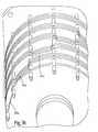
- FIG. 1a and 1b shows an ozone oxidizer 1 with a after outside dense process chamber housing 2.
- an ozone generating unit 3 is arranged in the process space 2a of Housing 2 in the process space 2a of Housing 2 in the process space 2a of Housing 2 in the process space 2a of Housing 2 in the process space 2a of Housing 2 in the process space 2a of Housing 2 is an ozone generating unit 3 is arranged.
- a Wasserzu Glassstutzen. 4 sealed inserted.
- the water supply 4 goes into one Venturi nozzle unit 5 over, which at the bottom of the Ozone generating unit 3 is mounted.
- the Venturi nozzle unit 5 consists of a venturi 5 a, within which a Injector 6 with outflow 7 centric is arranged.
- the injector 6 is through a Valve assembly 19 separated at the bottom of a stack of ozone generating elements 8 of the ozone generating unit 3 attached.
- About the water supply 4 inflowing Water is sent to the river at high speed Out
- the ozone generating elements 8 comprise two outer electrodes 9, 10 (see in particular Figure 1b), to the inside considered for electrical isolation in each case a glass plate 11, 12 follows.
- the glass plates are over spacers (not shown) positioned at a predetermined distance, wherein the space between the glass plates through one along the outer edge clamped extending sealing element gas-tight is completed.
- In the area between the Glass plates 11, 12 is preferably in the middle of a Inner electrode 15 is arranged, whose diameter is smaller as that of the glass plates 11, 12. This creates two Discharge spaces 13, 14, in which between the Glass plates 11, 12 each a corona discharge when applied from high voltage to the inner electrode 15 and when feeding of appropriate process gas can establish.
- a high voltage unit 17 is provided, which via connecting elements 17 a, 17 b the Internal electrodes can act on high voltage.
- the connecting elements 17b are centered in one Core area 8a of the ozone generating elements 8 each of Inner electrode 15 led to inner electrode 15.
- the Core area 8a is defined by the outer electrodes 9, 10, Sealing elements 16 and 8b annular wall sections closed gas-tight outside (see also Figure 2).
- the technical Oxygen, air or an oxygen gas mixture may be a gas inlet via a valve unit 18 is provided, the the process gas under pressure the gas-tight closed area the ozone generating unit 8 supplies.
- a to the Internal electrodes applied high voltage forms a silent electric discharge (corona discharge) due to which produces ozone in a known manner. That with ozone enriched process gas is via the valve assembly 19, the outflow openings 7 of the Venturi nozzle unit 5 is supplied and flows there into the process water flowing past it on.
- the valve assembly 19 prevents process water over Venturi nozzle unit 5 in the sealed area of the Ozone generating elements 8 can get.
- the effluent from the Venturi nozzle unit 5 process water enters an area 20 below the stacked ozone generating elements 8.
- the process water partially through outlet openings 21 in a jacket 24, the ozone generating elements and the Area 20 surrounds the area 20 in the process space 2 and can via an outlet 22 in the process chamber housing. 2 flow out.
- Down is the enclosed by the jacket 24 Volume limited by a bottom plate 24 a, in which the Venturi nozzle 5a is inserted tightly.
- the stacked ozone generating elements 8 become held by spacers 23 at a distance, so that between the ozone generating elements 8 except for one Core cross-section 28 passing through the annular wall sections 8a is defined, gaps 26, 29 arise.
- the ozone generating elements 8 For the formation of a circular, helical Water flow through the spaces 26, 29 over the stack the ozone generating elements 8 have the Ozone generating elements 8 at their outer edges Recesses 25a, 25b, 25c, 25d in the direction Lateral surface 24 looking in a kind of staircase structure are arranged (see in particular Figure 3a and 3b).
- the baffle 27 separates the gap 26 from the wall portion 8b to about the coat 24. Still small occurring columns to the outside can with appropriate Dimensioning neglected in hydrodynamic view become.
- the incoming through the recess 25a passes Water down to the back of the baffle 27.
- baffle 27 ensures that the same circular flow counterclockwise formed.
- Corresponding recesses 25c, 25d, etc. are in Overlying arranged ozone generating elements 8 with corresponding baffles 27 provided so that up to last overhead ozone generating element 8 a helical flow between the Set ozone generating elements 8, the first from above arranged ozone generating element, the ozone generating unit 3 in the process room 2 leaves. This water content can then also flow through the outlet 22.
- ozone generating unit 8 for the Treatment of water in swimming pools contributes to the warming of the water in the cooling of the In addition, ozone generating elements 8 assist the To heat pool water.
Landscapes
- Chemical & Material Sciences (AREA)
- Organic Chemistry (AREA)
- Inorganic Chemistry (AREA)
- Oxygen, Ozone, And Oxides In General (AREA)
- Paper (AREA)
Applications Claiming Priority (2)
| Application Number | Priority Date | Filing Date | Title |
|---|---|---|---|
| DE10220467 | 2002-05-07 | ||
| DE10220467 | 2002-05-07 |
Publications (2)
| Publication Number | Publication Date |
|---|---|
| EP1362829A1 true EP1362829A1 (fr) | 2003-11-19 |
| EP1362829B1 EP1362829B1 (fr) | 2006-11-22 |
Family
ID=7714497
Family Applications (1)
| Application Number | Title | Priority Date | Filing Date |
|---|---|---|---|
| EP03008683A Expired - Lifetime EP1362829B1 (fr) | 2002-05-07 | 2003-04-16 | Générateur d'ozone |
Country Status (5)
| Country | Link |
|---|---|
| US (1) | US6967009B2 (fr) |
| EP (1) | EP1362829B1 (fr) |
| AT (1) | ATE346016T1 (fr) |
| DE (2) | DE50305727D1 (fr) |
| NO (1) | NO20031856L (fr) |
Families Citing this family (2)
| Publication number | Priority date | Publication date | Assignee | Title |
|---|---|---|---|---|
| ATE346016T1 (de) | 2002-05-07 | 2006-12-15 | Hydro Elek K Gmbh | Ozongenerator |
| DE102004008431A1 (de) * | 2004-02-19 | 2005-09-08 | Uwa Umwelttechnik-Wasser-Abwasser Gmbh & Co. Kg | Ozonerzeuger |
Citations (4)
| Publication number | Priority date | Publication date | Assignee | Title |
|---|---|---|---|---|
| US3542664A (en) * | 1967-04-06 | 1970-11-24 | Cie Des Eaux Et De I Ozone Sa | Ozone-producing apparatus |
| US3899683A (en) * | 1967-01-04 | 1975-08-12 | Purification Sciences Inc | Dielectric liquid-immersed corona generator |
| EP0554457A1 (fr) * | 1991-08-08 | 1993-08-11 | Sumitomo Precision Products Company Limited | Ozoneur en forme de plaque |
| US20010041154A1 (en) * | 1998-08-21 | 2001-11-15 | Kabushiki Kaisha Toshiba | Ozonizing unit, ozone generator and ozone-processing system |
Family Cites Families (4)
| Publication number | Priority date | Publication date | Assignee | Title |
|---|---|---|---|---|
| US2260831A (en) * | 1936-03-05 | 1941-10-28 | American Ozone Company | Electric ozone generator |
| DE3247373A1 (de) | 1982-12-22 | 1984-06-28 | Bruno Bachhofer | Ozonerzeuger mit runden plattenelektroden in stapelbauweise |
| JP3654409B2 (ja) | 1998-03-24 | 2005-06-02 | 住友精密工業株式会社 | オゾン発生装置用放電セル及びその製造方法 |
| ATE346016T1 (de) | 2002-05-07 | 2006-12-15 | Hydro Elek K Gmbh | Ozongenerator |
-
2003
- 2003-04-16 AT AT03008683T patent/ATE346016T1/de not_active IP Right Cessation
- 2003-04-16 DE DE50305727T patent/DE50305727D1/de not_active Expired - Lifetime
- 2003-04-16 DE DE10317475A patent/DE10317475A1/de not_active Withdrawn
- 2003-04-16 EP EP03008683A patent/EP1362829B1/fr not_active Expired - Lifetime
- 2003-04-25 NO NO20031856A patent/NO20031856L/no not_active Application Discontinuation
- 2003-05-07 US US10/430,387 patent/US6967009B2/en not_active Expired - Fee Related
Patent Citations (4)
| Publication number | Priority date | Publication date | Assignee | Title |
|---|---|---|---|---|
| US3899683A (en) * | 1967-01-04 | 1975-08-12 | Purification Sciences Inc | Dielectric liquid-immersed corona generator |
| US3542664A (en) * | 1967-04-06 | 1970-11-24 | Cie Des Eaux Et De I Ozone Sa | Ozone-producing apparatus |
| EP0554457A1 (fr) * | 1991-08-08 | 1993-08-11 | Sumitomo Precision Products Company Limited | Ozoneur en forme de plaque |
| US20010041154A1 (en) * | 1998-08-21 | 2001-11-15 | Kabushiki Kaisha Toshiba | Ozonizing unit, ozone generator and ozone-processing system |
Also Published As
| Publication number | Publication date |
|---|---|
| DE10317475A1 (de) | 2003-11-27 |
| US6967009B2 (en) | 2005-11-22 |
| NO20031856L (no) | 2003-11-10 |
| ATE346016T1 (de) | 2006-12-15 |
| NO20031856D0 (no) | 2003-04-25 |
| US20040028577A1 (en) | 2004-02-12 |
| EP1362829B1 (fr) | 2006-11-22 |
| DE50305727D1 (de) | 2007-01-04 |
Similar Documents
| Publication | Publication Date | Title |
|---|---|---|
| DE69431724T2 (de) | Verbesserte elektrolysesysteme | |
| DE60023857T2 (de) | Ozon generator mit druckausgleich und verfahren zur herstellung von ozon | |
| DE10321916B4 (de) | Separatoreinheit und Brennstoffzelle mit Separatoreinheit | |
| DE202020102153U1 (de) | Erweiterte Elektrolysezelle mit Ionenaustauschermembran | |
| DE3422989A1 (de) | Vorrichtung zur erzeugung von ozon | |
| DE69213740T2 (de) | Multiröhrenozonerzeuger und verfahren zur herstellung desselben | |
| DE69108045T2 (de) | Vorrichtung zur erzeugung von ozon. | |
| DE19753720A1 (de) | Vorrichtung zur selektiven katalytischen Oxidation von Kohlenmonoxid | |
| DE3247374A1 (de) | Ozonerzeuger mit plattenfoermigen hochspannungs-elektroden | |
| DE2011202A1 (de) | Wärmetauscher | |
| WO2006092125A1 (fr) | Systeme pour desinfecter des liquides a faible conductibilite | |
| EP2156495B1 (fr) | Unité récurrente pour empilement de piles à combustible | |
| EP1362829B1 (fr) | Générateur d'ozone | |
| WO2002058083A2 (fr) | Plaque d'appui pourvue d'au moins une ouverture traversante et dispositif de derivation de hautes tensions-surtensions pourvu d'une telle plaque d'appui | |
| DE19717889C2 (de) | Vorrichtung und Verfahren zur Zersetzung von giftigen Schadstoffen in Abgasen von Verbrennungsprozessen | |
| DE929566C (de) | Induktorkuehlung bei Turbogeneratoren mit einseitig neben den in Nuten eingebetteten Wicklungen liegenden Kuehlungsnuten und Haltestuecken | |
| DE2349224C2 (de) | Elektrischer Druckgasschalter | |
| DE2939506C2 (de) | Vorrichtung zum Trennen von Isotopen | |
| DE3411335A1 (de) | Ionisationskammer, insbesondere fuer die ionisation von gasfoermigem sauerstoff | |
| DE2245849A1 (de) | Waermeaustauscher | |
| DE2705094C2 (de) | Koronaentladungsapparat | |
| DE102005025911A1 (de) | Brennstoffzellenanordnungen mit verbesserter Medienzufuhr | |
| DE3218259A1 (de) | Mehrzelliger gasgenerator | |
| DE418946C (de) | Einrichtung zur Erzeugung von Ozon auf elektrischem Wege | |
| DE553783C (de) | Elektrolytischer Zersetzer |
Legal Events
| Date | Code | Title | Description |
|---|---|---|---|
| PUAI | Public reference made under article 153(3) epc to a published international application that has entered the european phase |
Free format text: ORIGINAL CODE: 0009012 |
|
| AK | Designated contracting states |
Kind code of ref document: A1 Designated state(s): AT BE BG CH CY CZ DE DK EE ES FI FR GB GR HU IE IT LI LU MC NL PT RO SE SI SK TR |
|
| AX | Request for extension of the european patent |
Extension state: AL LT LV MK |
|
| 17P | Request for examination filed |
Effective date: 20040303 |
|
| 17Q | First examination report despatched |
Effective date: 20040325 |
|
| AKX | Designation fees paid |
Designated state(s): AT BE BG CH CY CZ DE DK EE ES FI FR GB GR HU IE IT LI LU MC NL PT RO SE SI SK TR |
|
| GRAP | Despatch of communication of intention to grant a patent |
Free format text: ORIGINAL CODE: EPIDOSNIGR1 |
|
| GRAS | Grant fee paid |
Free format text: ORIGINAL CODE: EPIDOSNIGR3 |
|
| GRAA | (expected) grant |
Free format text: ORIGINAL CODE: 0009210 |
|
| AK | Designated contracting states |
Kind code of ref document: B1 Designated state(s): AT BE BG CH CY CZ DE DK EE ES FI FR GB GR HU IE IT LI LU MC NL PT RO SE SI SK TR |
|
| PG25 | Lapsed in a contracting state [announced via postgrant information from national office to epo] |
Ref country code: IT Free format text: LAPSE BECAUSE OF FAILURE TO SUBMIT A TRANSLATION OF THE DESCRIPTION OR TO PAY THE FEE WITHIN THE PRESCRIBED TIME-LIMIT;WARNING: LAPSES OF ITALIAN PATENTS WITH EFFECTIVE DATE BEFORE 2007 MAY HAVE OCCURRED AT ANY TIME BEFORE 2007. THE CORRECT EFFECTIVE DATE MAY BE DIFFERENT FROM THE ONE RECORDED. Effective date: 20061122 Ref country code: SI Free format text: LAPSE BECAUSE OF FAILURE TO SUBMIT A TRANSLATION OF THE DESCRIPTION OR TO PAY THE FEE WITHIN THE PRESCRIBED TIME-LIMIT Effective date: 20061122 Ref country code: CZ Free format text: LAPSE BECAUSE OF FAILURE TO SUBMIT A TRANSLATION OF THE DESCRIPTION OR TO PAY THE FEE WITHIN THE PRESCRIBED TIME-LIMIT Effective date: 20061122 Ref country code: NL Free format text: LAPSE BECAUSE OF FAILURE TO SUBMIT A TRANSLATION OF THE DESCRIPTION OR TO PAY THE FEE WITHIN THE PRESCRIBED TIME-LIMIT Effective date: 20061122 Ref country code: RO Free format text: LAPSE BECAUSE OF FAILURE TO SUBMIT A TRANSLATION OF THE DESCRIPTION OR TO PAY THE FEE WITHIN THE PRESCRIBED TIME-LIMIT Effective date: 20061122 Ref country code: SK Free format text: LAPSE BECAUSE OF FAILURE TO SUBMIT A TRANSLATION OF THE DESCRIPTION OR TO PAY THE FEE WITHIN THE PRESCRIBED TIME-LIMIT Effective date: 20061122 Ref country code: FI Free format text: LAPSE BECAUSE OF FAILURE TO SUBMIT A TRANSLATION OF THE DESCRIPTION OR TO PAY THE FEE WITHIN THE PRESCRIBED TIME-LIMIT Effective date: 20061122 Ref country code: IE Free format text: LAPSE BECAUSE OF FAILURE TO SUBMIT A TRANSLATION OF THE DESCRIPTION OR TO PAY THE FEE WITHIN THE PRESCRIBED TIME-LIMIT Effective date: 20061122 |
|
| REG | Reference to a national code |
Ref country code: GB Ref legal event code: FG4D Free format text: NOT ENGLISH |
|
| REG | Reference to a national code |
Ref country code: CH Ref legal event code: EP |
|
| REG | Reference to a national code |
Ref country code: IE Ref legal event code: FG4D Free format text: LANGUAGE OF EP DOCUMENT: GERMAN |
|
| REF | Corresponds to: |
Ref document number: 50305727 Country of ref document: DE Date of ref document: 20070104 Kind code of ref document: P |
|
| PG25 | Lapsed in a contracting state [announced via postgrant information from national office to epo] |
Ref country code: BG Free format text: LAPSE BECAUSE OF FAILURE TO SUBMIT A TRANSLATION OF THE DESCRIPTION OR TO PAY THE FEE WITHIN THE PRESCRIBED TIME-LIMIT Effective date: 20070222 Ref country code: DK Free format text: LAPSE BECAUSE OF FAILURE TO SUBMIT A TRANSLATION OF THE DESCRIPTION OR TO PAY THE FEE WITHIN THE PRESCRIBED TIME-LIMIT Effective date: 20070222 Ref country code: SE Free format text: LAPSE BECAUSE OF FAILURE TO SUBMIT A TRANSLATION OF THE DESCRIPTION OR TO PAY THE FEE WITHIN THE PRESCRIBED TIME-LIMIT Effective date: 20070222 |
|
| PG25 | Lapsed in a contracting state [announced via postgrant information from national office to epo] |
Ref country code: ES Free format text: LAPSE BECAUSE OF FAILURE TO SUBMIT A TRANSLATION OF THE DESCRIPTION OR TO PAY THE FEE WITHIN THE PRESCRIBED TIME-LIMIT Effective date: 20070305 |
|
| PG25 | Lapsed in a contracting state [announced via postgrant information from national office to epo] |
Ref country code: PT Free format text: LAPSE BECAUSE OF FAILURE TO SUBMIT A TRANSLATION OF THE DESCRIPTION OR TO PAY THE FEE WITHIN THE PRESCRIBED TIME-LIMIT Effective date: 20070423 |
|
| NLV1 | Nl: lapsed or annulled due to failure to fulfill the requirements of art. 29p and 29m of the patents act | ||
| GBV | Gb: ep patent (uk) treated as always having been void in accordance with gb section 77(7)/1977 [no translation filed] |
Effective date: 20061122 |
|
| REG | Reference to a national code |
Ref country code: IE Ref legal event code: FD4D |
|
| EN | Fr: translation not filed | ||
| PLBE | No opposition filed within time limit |
Free format text: ORIGINAL CODE: 0009261 |
|
| STAA | Information on the status of an ep patent application or granted ep patent |
Free format text: STATUS: NO OPPOSITION FILED WITHIN TIME LIMIT |
|
| 26N | No opposition filed |
Effective date: 20070823 |
|
| PG25 | Lapsed in a contracting state [announced via postgrant information from national office to epo] |
Ref country code: GB Free format text: LAPSE BECAUSE OF FAILURE TO SUBMIT A TRANSLATION OF THE DESCRIPTION OR TO PAY THE FEE WITHIN THE PRESCRIBED TIME-LIMIT Effective date: 20061122 |
|
| REG | Reference to a national code |
Ref country code: CH Ref legal event code: PL |
|
| BERE | Be: lapsed |
Owner name: HYDRO-ELEKTRIK G.M.B.H. Effective date: 20070430 |
|
| PG25 | Lapsed in a contracting state [announced via postgrant information from national office to epo] |
Ref country code: CH Free format text: LAPSE BECAUSE OF NON-PAYMENT OF DUE FEES Effective date: 20070430 Ref country code: LI Free format text: LAPSE BECAUSE OF NON-PAYMENT OF DUE FEES Effective date: 20070430 |
|
| PG25 | Lapsed in a contracting state [announced via postgrant information from national office to epo] |
Ref country code: BE Free format text: LAPSE BECAUSE OF NON-PAYMENT OF DUE FEES Effective date: 20070430 |
|
| PG25 | Lapsed in a contracting state [announced via postgrant information from national office to epo] |
Ref country code: FR Free format text: LAPSE BECAUSE OF FAILURE TO SUBMIT A TRANSLATION OF THE DESCRIPTION OR TO PAY THE FEE WITHIN THE PRESCRIBED TIME-LIMIT Effective date: 20070713 Ref country code: GR Free format text: LAPSE BECAUSE OF FAILURE TO SUBMIT A TRANSLATION OF THE DESCRIPTION OR TO PAY THE FEE WITHIN THE PRESCRIBED TIME-LIMIT Effective date: 20070223 |
|
| PG25 | Lapsed in a contracting state [announced via postgrant information from national office to epo] |
Ref country code: AT Free format text: LAPSE BECAUSE OF NON-PAYMENT OF DUE FEES Effective date: 20070416 |
|
| PG25 | Lapsed in a contracting state [announced via postgrant information from national office to epo] |
Ref country code: FR Free format text: LAPSE BECAUSE OF FAILURE TO SUBMIT A TRANSLATION OF THE DESCRIPTION OR TO PAY THE FEE WITHIN THE PRESCRIBED TIME-LIMIT Effective date: 20061122 |
|
| PG25 | Lapsed in a contracting state [announced via postgrant information from national office to epo] |
Ref country code: EE Free format text: LAPSE BECAUSE OF FAILURE TO SUBMIT A TRANSLATION OF THE DESCRIPTION OR TO PAY THE FEE WITHIN THE PRESCRIBED TIME-LIMIT Effective date: 20061122 |
|
| PG25 | Lapsed in a contracting state [announced via postgrant information from national office to epo] |
Ref country code: MC Free format text: LAPSE BECAUSE OF NON-PAYMENT OF DUE FEES Effective date: 20070430 |
|
| PG25 | Lapsed in a contracting state [announced via postgrant information from national office to epo] |
Ref country code: LU Free format text: LAPSE BECAUSE OF NON-PAYMENT OF DUE FEES Effective date: 20070416 Ref country code: CY Free format text: LAPSE BECAUSE OF FAILURE TO SUBMIT A TRANSLATION OF THE DESCRIPTION OR TO PAY THE FEE WITHIN THE PRESCRIBED TIME-LIMIT Effective date: 20061122 |
|
| PG25 | Lapsed in a contracting state [announced via postgrant information from national office to epo] |
Ref country code: TR Free format text: LAPSE BECAUSE OF FAILURE TO SUBMIT A TRANSLATION OF THE DESCRIPTION OR TO PAY THE FEE WITHIN THE PRESCRIBED TIME-LIMIT Effective date: 20061122 Ref country code: HU Free format text: LAPSE BECAUSE OF FAILURE TO SUBMIT A TRANSLATION OF THE DESCRIPTION OR TO PAY THE FEE WITHIN THE PRESCRIBED TIME-LIMIT Effective date: 20070523 |
|
| PGFP | Annual fee paid to national office [announced via postgrant information from national office to epo] |
Ref country code: DE Payment date: 20140513 Year of fee payment: 12 |
|
| REG | Reference to a national code |
Ref country code: DE Ref legal event code: R119 Ref document number: 50305727 Country of ref document: DE |
|
| PG25 | Lapsed in a contracting state [announced via postgrant information from national office to epo] |
Ref country code: DE Free format text: LAPSE BECAUSE OF NON-PAYMENT OF DUE FEES Effective date: 20151103 |