EP1362760A1 - Dämpfungsvorrichtung für einen nicht motorisierten Wagen und Wagen - Google Patents
Dämpfungsvorrichtung für einen nicht motorisierten Wagen und Wagen Download PDFInfo
- Publication number
- EP1362760A1 EP1362760A1 EP02405391A EP02405391A EP1362760A1 EP 1362760 A1 EP1362760 A1 EP 1362760A1 EP 02405391 A EP02405391 A EP 02405391A EP 02405391 A EP02405391 A EP 02405391A EP 1362760 A1 EP1362760 A1 EP 1362760A1
- Authority
- EP
- European Patent Office
- Prior art keywords
- damping device
- damping
- elements
- profile
- optionally
- Prior art date
- Legal status (The legal status is an assumption and is not a legal conclusion. Google has not performed a legal analysis and makes no representation as to the accuracy of the status listed.)
- Granted
Links
- 238000013016 damping Methods 0.000 title claims abstract description 101
- 239000000463 material Substances 0.000 claims description 13
- 230000006835 compression Effects 0.000 claims description 4
- 238000007906 compression Methods 0.000 claims description 4
- 229910052751 metal Inorganic materials 0.000 claims description 4
- 239000002184 metal Substances 0.000 claims description 4
- 239000000853 adhesive Substances 0.000 claims description 2
- 230000001070 adhesive effect Effects 0.000 claims description 2
- 238000004519 manufacturing process Methods 0.000 description 4
- 238000009415 formwork Methods 0.000 description 2
- 238000003780 insertion Methods 0.000 description 2
- 230000037431 insertion Effects 0.000 description 2
- 238000009434 installation Methods 0.000 description 2
- 238000000034 method Methods 0.000 description 2
- 230000035939 shock Effects 0.000 description 2
- 235000012976 tarts Nutrition 0.000 description 2
- 229910052782 aluminium Inorganic materials 0.000 description 1
- XAGFODPZIPBFFR-UHFFFAOYSA-N aluminium Chemical compound [Al] XAGFODPZIPBFFR-UHFFFAOYSA-N 0.000 description 1
- 239000003795 chemical substances by application Substances 0.000 description 1
- 238000005253 cladding Methods 0.000 description 1
- 238000000151 deposition Methods 0.000 description 1
- 230000000694 effects Effects 0.000 description 1
- 235000013305 food Nutrition 0.000 description 1
- 230000009931 harmful effect Effects 0.000 description 1
- 150000002739 metals Chemical class 0.000 description 1
- 230000003287 optical effect Effects 0.000 description 1
- 238000009420 retrofitting Methods 0.000 description 1
- 239000002689 soil Substances 0.000 description 1
- 125000006850 spacer group Chemical group 0.000 description 1
Images

Classifications
-
- B—PERFORMING OPERATIONS; TRANSPORTING
- B62—LAND VEHICLES FOR TRAVELLING OTHERWISE THAN ON RAILS
- B62B—HAND-PROPELLED VEHICLES, e.g. HAND CARTS OR PERAMBULATORS; SLEDGES
- B62B3/00—Hand carts having more than one axis carrying transport wheels; Steering devices therefor; Equipment therefor
- B62B3/006—Hand carts having more than one axis carrying transport wheels; Steering devices therefor; Equipment therefor for stacking objects like trays, bobbins, chains
-
- B—PERFORMING OPERATIONS; TRANSPORTING
- B62—LAND VEHICLES FOR TRAVELLING OTHERWISE THAN ON RAILS
- B62B—HAND-PROPELLED VEHICLES, e.g. HAND CARTS OR PERAMBULATORS; SLEDGES
- B62B2301/00—Wheel arrangements; Steering; Stability; Wheel suspension
- B62B2301/20—Resilient wheel suspension using springs
Definitions
- the invention relates to a damping device for a non-motorized cars and one with this Damping device provided non-motorized cars the preamble of claim 1 or 10.
- non-motorized cars For depositing and / or transporting materials and Goods in service companies, for example restaurants, Canteens and hotels, in production or sales facilities, non-motorized cars are often used, such as for example in [1], catalog 1999 of the company ellema, CH-8951 Fahrweid are shown and described.
- Figure 2 and Figure 3 show the above-mentioned plateaux clearing wheelchair used damping device in which a the base frame 300 provided on the wheels 4 of the car elastic elements 2 with a frame 11 to the Carrying material-supporting structure 1 of the car connected is.
- Impellers 4 act on the base frame 300, therefore heavily damped transferred to the support structure 1 of the car.
- damping device A disadvantage of this damping device, however, is that the damping means used or the elastic elements 2 appear visually, which is particularly true in sales outlets is undesirable.
- the damping device installed If necessary, it must be covered with cladding, which causes additional effort.
- the present invention is therefore based on the object a damping device for a non-motorized car to create which are not with the described shortcomings is afflicted.
- a damping device is to be created, which can be assembled with simple measures, no annoying Changes in the height of the car caused and after Installation does not interfere.
- non-motorized cars should also be retrofitted little effort with a damping device according to the invention be equipable.
- the damping device according to the invention which is not in motorized car is installed, has damping elements on, by means of which a preferably rectangular in itself closed end frame one for carrying materials serving support structure with a wheeled Basic structure is connectable. At least according to the invention a mounting profile is provided, which with the end frame connected and shaped and assembled so that the on the one hand with the mounting profile and on the other hand with the Basic structure connected damping elements within and at least partially at the same level as the final frame are arranged.
- the damping device can therefore installed without changing the height of the carriage.
- the damping device makes the otherwise free space within the arranged on the underside of the support structure Final frame filled without the dimensions of the Change car or the damping elements disturbing in Appearance.
- the damping device can also with little effort installed so that they are already in use Cart with simple measures with an inventive Damping device can be retrofitted.
- the wheels of the car with the damping device are also almost in the same position as the not equipped with a damping device, so that the stability of the car after installing the damping device remains unchanged or, due to the Damping effect is even noticeably improved.
- damping elements there are four damping elements provided, each at a corner of the if appropriate, a hollow profile end frame is arranged.
- the damping elements and the impellers are arranged in an axis.
- the mounting profile preferably has an open, U-profile to accommodate the damping elements on, possibly with outward-facing flanges is provided on the underside of the end frame be attached. With this configuration of the mounting profile the installed damping device is hardly recognizable.
- Two are preferably arranged parallel to one another Mounting profiles provided, each with two damping elements connected and their dimensions according to the required Stability are chosen.
- the basic structure is preferably a self-contained structure rectangular base frame formed, which if necessary from screwed or welded together, i.e. there are detachable or firmly connected sections.
- an optionally adjustable distance is provided by which the maximum compression of the assigned damping element is determined, whereby on the one hand the damping elements are protected and on the other hand a tilting of the wagon when the incline is excessive Support structure is prevented.
- the damping elements have on their top and bottom if necessary, adhesive fasteners on, by means of which they with the mounting profile and the Base structure can be connected, if necessary screwed.
- the damping elements have at least one optionally with cavities or plastic body at least one metal spring element or a hydraulic one Damping element on. Further configurations of the damping elements, which are adjustable if necessary, are in can be used professionally.
- a car provided with a damping device can, like described in the introduction, for the transport of any Materials and goods are used.
- the supporting structure and an optionally provided formwork will be the adapted to the respective application.
- the supporting structure with door and wall elements by means of which, for example, a cabinet is formed, or only be provided with horizontally arranged strips, which the Allow insertion and holding of trays.
- the damping device provided wagons at least the application options of unsprung Dare.
- other, especially fragile goods in the cars according to the invention with greatly reduced Transport risks are conveyed.
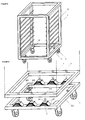
- Figure 1 shows a known unsprung shelf trolley that Wheels 4 is manually slidably mounted.
- Various Embodiments of shelf trolleys are for example in [1], Chapter 2 shown and described. Typical of all of these Dare is that it is a material-picking Have support structure 1, which on the underside Have end frame 11.
- the support structure 1 of the shelf trolley shown in Figure 1 is provided with strips 15, which the insertion and holding of Allow trays (see [1], page 2.2, picture "Plateaux clearing trolley”).
- the rectangular self-contained end frame 11 is connected to wheels 4 by means of mounting plates 12.
- Essential for the finishing frame 11 is that it has a sufficient has high strength to be transported Wear materials and keep the wheels 4 stable, so that when moving the car under load there are no annoying Deformations occur. Taking this into account Claims can therefore have different shapes and dimensions can be chosen for the final frame 11.
- FIG. 1 Various of the carriages shown in [1] are therefore sprung, i.e. provided with a damping device.
- Figure 2 and Figure 3 show the above-mentioned plateaux clearing wheelchair (see [1], page 2.2) used damping device in which a base frame 300 provided with the wheels 4 of the carriage via elastic elements 2, hereinafter damping elements, with the end frame 11 of the support structure 1 is connected.
- figure 2 shows the damping device during and
- FIG. 3 shows the Damping device after assembly.
- Glued plates 21 On the top and bottom of the damping elements 2 are Glued plates 21, which are provided with screws 22, which above through holes 111 in the end frame 11 and below Drilled holes in the base frame 300 and then with Screw nuts 23 are screwed.
- the damping elements 2 preferably have in the shown Design a compressible provided with cavities Plastic body.
- Other damping elements for example metal spring elements, pneumatic or hydraulic Damping means that are adjustable, if necessary also usable.
- Impellers 4 act on the base frame 300, therefore heavily damped transferred to the support structure 1 of the car, whereby the transported materials, but also the whole Drive of the car is protected.
- this damping device occurs used damping agent 2 disturbing in appearance, which is why often a formwork is to be provided that an additional Costs incurred. It is also easy to see that the height of the car changes.
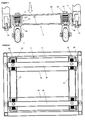
- Figure 4 shows a sectional view from the side Damping device according to the invention installed in a car, which at least one with the end frame 11th connected mounting profile 50 which is shaped and is mounted on the one hand with the mounting profile 50 and on the other hand, damping elements connected to the base structure 3 2 within and at least partially at the same level of the end frame 11 are arranged.
- the damping device can therefore be installed without that the height of the car changes. Through the damping device the otherwise free space within the Bottom of the support structure 1 arranged end frame 11, which has a hollow profile, therefore filled in without change the dimensions of the car or the damping elements 2 to appear disruptive.
- this has Mounting profile 50 an open downward, the inclusion of Damping elements 2 serving U-profile, which with outward flanges 51 is provided on the Bottom of the end frame 11 by means of screws 38 are attached.
- the end frame 11 is therefore independent whether or not a damping device is installed at least approximately the same height.
- each of the damping elements 2 is close to one Corner of the end frame 11, above a wheel 4 of the car arranged.
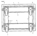
- FIGS. 6 and 7 in which the damping device from above (with a Section through the support structure 1) is shown further that the base structure 3 by a stable rectangular base frame is formed from Bolts and nuts 39 screwed together Pieces 31, 32 exists.
- the base frame can also be made from welded or screwed profile pieces are formed, for example a T, U or hollow profile exhibit.
- the sections 31, 32 have U-profiles lying back to back on, whereby the stability of the base structure 3 is increased accordingly.
- FIG. 5 shows the damping device of Figure 4, after eccentric, excessive loading of the support structure 1, under Action of a force F. It can be seen that the The left damping element 2 shown corresponds to that in FIG. 4 drawn distance a, i.e. until mutual Impact of the mounting profile 50 and the corresponding U-profile Part 31 was compressed. Another Compression of the damping element 2, if necessary damage or tipping the wagon could be reliably prevented.
- the distance a, through which the permissible compression of the damping elements 2 is therefore determined by the choice of the profile of the Pieces 31, or by the length of the wing parts 311 of the U-profile certainly.
- the distance a can be adjusted accordingly Design of various elements of the mounting profile 50 and / or the base structure 3 can be predetermined. Furthermore are further, if necessary, adjustable spacer elements can be used.
- the damping device according to the invention and with this Dampers equipped with dampers have been preferred Embodiments described and shown. Using the inventive Teaching, however, are other professional designs realizable.
- the device parts in particular the profile parts selectable as well as various manufacturing materials, preferably light metals such as aluminum Manufacturing usable.
- various means be used to connect the device parts.
- the positions where the connection points are provided be chosen in different ways.
- damping elements Spring elements, pneumatic or hydraulic damping elements, which have the required dimensions, can be used without any problems.
- the use of the Motorized cars are in particular those described in [1] but, especially due to the installed damping device, numerous other applications are also possible.
Landscapes
- Engineering & Computer Science (AREA)
- Chemical & Material Sciences (AREA)
- Combustion & Propulsion (AREA)
- Transportation (AREA)
- Mechanical Engineering (AREA)
- Vibration Prevention Devices (AREA)
- Handcart (AREA)
- Vehicle Body Suspensions (AREA)
- Carriages For Children, Sleds, And Other Hand-Operated Vehicles (AREA)
- Axle Suspensions And Sidecars For Cycles (AREA)
Abstract
Description
- Figur 1
- einen bekannten zur Aufnahme von Tablaren dienenden Regalwagen,
- Figur 2
- die Dämpfungsvorrichtung eines bekannten Wagens während der Montage,
- Figur 3
- die Dämpfungsvorrichtung des Wagens von Figur 2 nach der Montage,
- Figur 4
- eine erfindungsgemässe Dämpfungsvorrichtung in einem Seitenschnitt dargestellt,
- Figur 5
- die Dämpfungsvorrichtung von Figur 4 unter Einwirkung einer Kraft F,
- Figur 6
- die Dämpfungsvorrichtung von Figur 4 von oben gesehen, und
- Figur 7
- die Dämpfungsvorrichtung von Figur 4 bzw. der mit der Dämpfungsvorrichtung versehene Wagen von unten gesehen.
Claims (10)
- Dämpfungsvorrichtung für einen nicht motorisierten Wagen, mit Dämpfungselementen (2), mittels denen ein gegebenenfalls rechteckig in sich geschlossener Abschlussrahmen (11) einer zum Tragen von Materialien dienenden Tragstruktur (1) mit einer mit Rädern (2) versehenen Basisstruktur (3) verbindbar ist, dadurch gekennzeichnet, dass wenigstens ein mit dem Abschlussrahmen (11) verbundenes Montageprofil (50) vorgesehen ist, das derart geformt und montiert ist, dass die einerseits mit dem Montageprofil (50) und andererseits mit der Basisstruktur (3) verbundenen Dämpfungselemente (2) innerhalb und zumindest teilweise auf gleicher Höhe des Abschlussrahmens (11) angeordnet sind.
- Dämpfungsvorrichtung nach Anspruch 1, dadurch gekennzeichnet, dass das wenigstens eine Montageprofil (50) ein nach unten geöffnetes, der Aufnahme der Dämpfungselemente (2) dienendes U-Profil aufweist, das gegebenenfalls mit nach aussen gerichteten Flanschen (51) versehen ist, die an der Unterseite des Abschlussrahmens (11) befestigt sind.
- Dämpfungsvorrichtung nach Anspruch 1 oder 2, dadurch gekennzeichnet, dass vier Dämpfungselemente (2) vorgesehen sind, von denen jedes an einer Ecke des rechteckig in sich geschlossenen, gegebenenfalls ein Hohlprofil aufweisenden Abschlussrahmens (11), gegebenenfalls direkt über einem Rad (4) des Wagens, angeordnet ist.
- Dämpfungsvorrichtung nach Anspruch 1, 2 oder 3, dadurch gekennzeichnet, dass zwei parallel zueinander angeordnete Montageprofile (50) vorgesehen sind, die je mit zwei Dämpfungselementen (2) verbunden sind.
- Dämpfungsvorrichtung nach einem der Ansprüche 1 bis 4, dadurch gekennzeichnet, dass die Basisstruktur (3) ein rechteckiger Basisrahmen ist, der gegebenenfalls aus miteinander verschraubten oder verschweissten Teilstücken (31, 32) besteht.
- Dämpfungsvorrichtung nach Anspruch 5, dadurch gekennzeichnet, dass wenigstens eines der miteinander verbundenen Teilstücke (31, 32) ein Hohlprofil oder ein nach aussen geöffnetes, von der Basisstruktur (3) wegweisendes U-Profil aufweist.
- Dämpfungsvorrichtung nach einem der Ansprüche 1 bis 6, dadurch gekennzeichnet, dass zwischen Elementen (311) des Montageprofils (50) und der Basisstruktur (3) ein gegebenenfalls einstellbarer Abstand (a) vorgesehen ist, durch den die maximale Kompression des zugeordneten Dämpfungselementes (2) festgelegt wird.
- Dämpfungsvorrichtung nach einem der Ansprüche 1 bis 7, dadurch gekennzeichnet, dass die Dämpfungselemente (2) an der Oberseite und der Unterseite gegebenenfalls mittels Klebstoff befestigte Verbindungsmittel (21, 22) aufweisen, mittels denen sie mit dem Montageprofil (50) und der Basisstruktur (3) verbindbar, gegebenenfalls verschraubbar sind.
- Dämpfungsvorrichtung nach einem der Ansprüche 1 bis 8, dadurch gekennzeichnet, dass die Dämpfungselemente (2) wenigstens einen gegebenenfalls mit Hohlräumen versehenen Kunststoffkörper, ein metallenes Federelement oder ein hydraulisches oder pneumatisches Dämpfungselement aufweisen.
- Wagen mit einer Dämpfungsvorrichtung nach einem der Ansprüche 1 bis 9.
Priority Applications (3)
| Application Number | Priority Date | Filing Date | Title |
|---|---|---|---|
| AT02405391T ATE425064T1 (de) | 2002-05-14 | 2002-05-14 | Dämpfungsvorrichtung für einen nicht motorisierten wagen und wagen |
| EP02405391A EP1362760B1 (de) | 2002-05-14 | 2002-05-14 | Dämpfungsvorrichtung für einen nicht motorisierten Wagen und Wagen |
| DE50213350T DE50213350D1 (de) | 2002-05-14 | 2002-05-14 | Dämpfungsvorrichtung für einen nicht motorisierten Wagen und Wagen |
Applications Claiming Priority (1)
| Application Number | Priority Date | Filing Date | Title |
|---|---|---|---|
| EP02405391A EP1362760B1 (de) | 2002-05-14 | 2002-05-14 | Dämpfungsvorrichtung für einen nicht motorisierten Wagen und Wagen |
Publications (2)
| Publication Number | Publication Date |
|---|---|
| EP1362760A1 true EP1362760A1 (de) | 2003-11-19 |
| EP1362760B1 EP1362760B1 (de) | 2009-03-11 |
Family
ID=29266033
Family Applications (1)
| Application Number | Title | Priority Date | Filing Date |
|---|---|---|---|
| EP02405391A Expired - Lifetime EP1362760B1 (de) | 2002-05-14 | 2002-05-14 | Dämpfungsvorrichtung für einen nicht motorisierten Wagen und Wagen |
Country Status (3)
| Country | Link |
|---|---|
| EP (1) | EP1362760B1 (de) |
| AT (1) | ATE425064T1 (de) |
| DE (1) | DE50213350D1 (de) |
Cited By (5)
| Publication number | Priority date | Publication date | Assignee | Title |
|---|---|---|---|---|
| CN103879472A (zh) * | 2012-12-19 | 2014-06-25 | 金宝电子工业股份有限公司 | 驱动装置与搬运车 |
| CN103963807A (zh) * | 2014-05-08 | 2014-08-06 | 谢娟 | 一种防震推车 |
| CN108099983A (zh) * | 2017-12-18 | 2018-06-01 | 合肥超凡快递咨询有限公司界首营业部 | 一种基于物流用具有减震轮的手推车 |
| CN108974080A (zh) * | 2018-09-11 | 2018-12-11 | 天津星原汽车零部件有限公司 | 一种汽车零部件生产输料装置 |
| CN109131503A (zh) * | 2018-09-10 | 2019-01-04 | 临汾聚友泉电子科技有限公司 | 一种高效率的办公用品搬运装置及其使用方法 |
Citations (3)
| Publication number | Priority date | Publication date | Assignee | Title |
|---|---|---|---|---|
| JPH08268462A (ja) * | 1995-03-28 | 1996-10-15 | Nissan Diesel Motor Co Ltd | 輸送用容器 |
| US5749589A (en) * | 1995-10-27 | 1998-05-12 | United Air Llines | Airline baggage cart |
| JPH11301490A (ja) * | 1998-04-16 | 1999-11-02 | Asahi:Kk | 緩衝台車 |
-
2002
- 2002-05-14 DE DE50213350T patent/DE50213350D1/de not_active Expired - Lifetime
- 2002-05-14 AT AT02405391T patent/ATE425064T1/de not_active IP Right Cessation
- 2002-05-14 EP EP02405391A patent/EP1362760B1/de not_active Expired - Lifetime
Patent Citations (3)
| Publication number | Priority date | Publication date | Assignee | Title |
|---|---|---|---|---|
| JPH08268462A (ja) * | 1995-03-28 | 1996-10-15 | Nissan Diesel Motor Co Ltd | 輸送用容器 |
| US5749589A (en) * | 1995-10-27 | 1998-05-12 | United Air Llines | Airline baggage cart |
| JPH11301490A (ja) * | 1998-04-16 | 1999-11-02 | Asahi:Kk | 緩衝台車 |
Non-Patent Citations (2)
| Title |
|---|
| PATENT ABSTRACTS OF JAPAN vol. 1997, no. 02 28 February 1997 (1997-02-28) * |
| PATENT ABSTRACTS OF JAPAN vol. 2000, no. 02 29 February 2000 (2000-02-29) * |
Cited By (5)
| Publication number | Priority date | Publication date | Assignee | Title |
|---|---|---|---|---|
| CN103879472A (zh) * | 2012-12-19 | 2014-06-25 | 金宝电子工业股份有限公司 | 驱动装置与搬运车 |
| CN103963807A (zh) * | 2014-05-08 | 2014-08-06 | 谢娟 | 一种防震推车 |
| CN108099983A (zh) * | 2017-12-18 | 2018-06-01 | 合肥超凡快递咨询有限公司界首营业部 | 一种基于物流用具有减震轮的手推车 |
| CN109131503A (zh) * | 2018-09-10 | 2019-01-04 | 临汾聚友泉电子科技有限公司 | 一种高效率的办公用品搬运装置及其使用方法 |
| CN108974080A (zh) * | 2018-09-11 | 2018-12-11 | 天津星原汽车零部件有限公司 | 一种汽车零部件生产输料装置 |
Also Published As
| Publication number | Publication date |
|---|---|
| DE50213350D1 (de) | 2009-04-23 |
| ATE425064T1 (de) | 2009-03-15 |
| EP1362760B1 (de) | 2009-03-11 |
Similar Documents
| Publication | Publication Date | Title |
|---|---|---|
| EP0541485B1 (de) | Fahrzeug | |
| EP3208174B1 (de) | Transportwagen | |
| DE19737712B4 (de) | Ladesystem für einen Stauraum eines Fahrzeugs | |
| DE102017001747A1 (de) | Zusammenklappbarer Einkaufs- und Transportwagen mit Aufnahmevorrichtung zum Transport von Waren und Gütern | |
| EP1362760B1 (de) | Dämpfungsvorrichtung für einen nicht motorisierten Wagen und Wagen | |
| EP2774634B1 (de) | Dialysemaschine mit selbsttragendem Maschinengehäuse | |
| EP1512606B1 (de) | Organisationswagen | |
| DE202014104729U1 (de) | Flurförderwagen | |
| EP0730075A1 (de) | Verschlussklappe mit einer Parallelogramm-Aufhängung sowie Unterbaukasten für Servicefahrzeuge mit einer solchen Verschlussklappe | |
| DE20303769U1 (de) | Montage- und/oder Werkstattwagen | |
| EP1630307B1 (de) | Mobile Toilettenräume | |
| DE202009011480U1 (de) | Einkaufswagen | |
| DE102011118947B3 (de) | Transportwagen | |
| EP1093988A1 (de) | Transportwagen | |
| EP0614792B1 (de) | Aussenlangträger für 2achsige Eisenbahngüterwagen | |
| DE19802959C2 (de) | Mobile Werkstatteinrichtung | |
| EP2933124B1 (de) | Nutzfahrzeug mit achsanschlag | |
| DE3123723A1 (de) | Heckgepaecktrager fuer kleinbusse, motorhomes usw. | |
| EP1762456A1 (de) | Transportgestell, insbesondere Rollwagen | |
| DE102013010648B4 (de) | Transportwagen mit Auflaufbremse | |
| EP4154861B1 (de) | Geräteschiene zum halten medizinischer geräte in patientennähe, und patientenmöbel | |
| DE102011122222A1 (de) | Transportwagen | |
| DE4003943C2 (de) | Ladesystem für Kombi-Fahrzeuge, Praktikautos mit Heckklappen oder Kleintransporter | |
| DE4124126C2 (de) | Bibliotheksbücherwagen | |
| DE29914648U1 (de) | Lade- und/oder Überfahrbordwand |
Legal Events
| Date | Code | Title | Description |
|---|---|---|---|
| PUAI | Public reference made under article 153(3) epc to a published international application that has entered the european phase |
Free format text: ORIGINAL CODE: 0009012 |
|
| AK | Designated contracting states |
Kind code of ref document: A1 Designated state(s): AT BE CH CY DE DK ES FI FR GB GR IE IT LI LU MC NL PT SE TR |
|
| AX | Request for extension of the european patent |
Extension state: AL LT LV MK RO SI |
|
| 17P | Request for examination filed |
Effective date: 20040519 |
|
| AKX | Designation fees paid |
Designated state(s): AT CH DE LI |
|
| 17Q | First examination report despatched |
Effective date: 20061107 |
|
| GRAP | Despatch of communication of intention to grant a patent |
Free format text: ORIGINAL CODE: EPIDOSNIGR1 |
|
| GRAS | Grant fee paid |
Free format text: ORIGINAL CODE: EPIDOSNIGR3 |
|
| GRAA | (expected) grant |
Free format text: ORIGINAL CODE: 0009210 |
|
| AK | Designated contracting states |
Kind code of ref document: B1 Designated state(s): AT CH DE LI |
|
| REG | Reference to a national code |
Ref country code: CH Ref legal event code: EP |
|
| REG | Reference to a national code |
Ref country code: CH Ref legal event code: NV Representative=s name: PETER RUTZ |
|
| REF | Corresponds to: |
Ref document number: 50213350 Country of ref document: DE Date of ref document: 20090423 Kind code of ref document: P |
|
| PLBE | No opposition filed within time limit |
Free format text: ORIGINAL CODE: 0009261 |
|
| STAA | Information on the status of an ep patent application or granted ep patent |
Free format text: STATUS: NO OPPOSITION FILED WITHIN TIME LIMIT |
|
| 26N | No opposition filed |
Effective date: 20091214 |
|
| PG25 | Lapsed in a contracting state [announced via postgrant information from national office to epo] |
Ref country code: AT Free format text: LAPSE BECAUSE OF NON-PAYMENT OF DUE FEES Effective date: 20090514 |
|
| PGFP | Annual fee paid to national office [announced via postgrant information from national office to epo] |
Ref country code: DE Payment date: 20101110 Year of fee payment: 9 |
|
| REG | Reference to a national code |
Ref country code: DE Ref legal event code: R119 Ref document number: 50213350 Country of ref document: DE Effective date: 20111201 |
|
| PG25 | Lapsed in a contracting state [announced via postgrant information from national office to epo] |
Ref country code: DE Free format text: LAPSE BECAUSE OF NON-PAYMENT OF DUE FEES Effective date: 20111201 |
|
| PGFP | Annual fee paid to national office [announced via postgrant information from national office to epo] |
Ref country code: CH Payment date: 20130819 Year of fee payment: 12 |
|
| REG | Reference to a national code |
Ref country code: CH Ref legal event code: PL |
|
| PG25 | Lapsed in a contracting state [announced via postgrant information from national office to epo] |
Ref country code: LI Free format text: LAPSE BECAUSE OF NON-PAYMENT OF DUE FEES Effective date: 20140531 Ref country code: CH Free format text: LAPSE BECAUSE OF NON-PAYMENT OF DUE FEES Effective date: 20140531 |