EP1362746A2 - Stossfänger für Fahrzeuge, insbesondere Kraftfahrzeuge - Google Patents
Stossfänger für Fahrzeuge, insbesondere Kraftfahrzeuge Download PDFInfo
- Publication number
- EP1362746A2 EP1362746A2 EP03005869A EP03005869A EP1362746A2 EP 1362746 A2 EP1362746 A2 EP 1362746A2 EP 03005869 A EP03005869 A EP 03005869A EP 03005869 A EP03005869 A EP 03005869A EP 1362746 A2 EP1362746 A2 EP 1362746A2
- Authority
- EP
- European Patent Office
- Prior art keywords
- horn
- cover element
- covering
- lamp
- bumper according
- Prior art date
- Legal status (The legal status is an assumption and is not a legal conclusion. Google has not performed a legal analysis and makes no representation as to the accuracy of the status listed.)
- Granted
Links
Images
Classifications
-
- B—PERFORMING OPERATIONS; TRANSPORTING
- B60—VEHICLES IN GENERAL
- B60R—VEHICLES, VEHICLE FITTINGS, OR VEHICLE PARTS, NOT OTHERWISE PROVIDED FOR
- B60R19/00—Wheel guards; Radiator guards, e.g. grilles; Obstruction removers; Fittings damping bouncing force in collisions
- B60R19/02—Bumpers, i.e. impact receiving or absorbing members for protecting vehicles or fending off blows from other vehicles or objects
- B60R19/48—Bumpers, i.e. impact receiving or absorbing members for protecting vehicles or fending off blows from other vehicles or objects combined with, or convertible into, other devices or objects, e.g. bumpers combined with road brushes, bumpers convertible into beds
- B60R19/50—Bumpers, i.e. impact receiving or absorbing members for protecting vehicles or fending off blows from other vehicles or objects combined with, or convertible into, other devices or objects, e.g. bumpers combined with road brushes, bumpers convertible into beds with lights or registration plates
-
- B—PERFORMING OPERATIONS; TRANSPORTING
- B60—VEHICLES IN GENERAL
- B60Q—ARRANGEMENT OF SIGNALLING OR LIGHTING DEVICES, THE MOUNTING OR SUPPORTING THEREOF OR CIRCUITS THEREFOR, FOR VEHICLES IN GENERAL
- B60Q1/00—Arrangement of optical signalling or lighting devices, the mounting or supporting thereof or circuits therefor
- B60Q1/02—Arrangement of optical signalling or lighting devices, the mounting or supporting thereof or circuits therefor the devices being primarily intended to illuminate the way ahead or to illuminate other areas of way or environments
- B60Q1/04—Arrangement of optical signalling or lighting devices, the mounting or supporting thereof or circuits therefor the devices being primarily intended to illuminate the way ahead or to illuminate other areas of way or environments the devices being headlights
- B60Q1/0491—Shock absorbing devices therefor
-
- B—PERFORMING OPERATIONS; TRANSPORTING
- B60—VEHICLES IN GENERAL
- B60R—VEHICLES, VEHICLE FITTINGS, OR VEHICLE PARTS, NOT OTHERWISE PROVIDED FOR
- B60R19/00—Wheel guards; Radiator guards, e.g. grilles; Obstruction removers; Fittings damping bouncing force in collisions
- B60R19/02—Bumpers, i.e. impact receiving or absorbing members for protecting vehicles or fending off blows from other vehicles or objects
- B60R19/48—Bumpers, i.e. impact receiving or absorbing members for protecting vehicles or fending off blows from other vehicles or objects combined with, or convertible into, other devices or objects, e.g. bumpers combined with road brushes, bumpers convertible into beds
- B60R19/50—Bumpers, i.e. impact receiving or absorbing members for protecting vehicles or fending off blows from other vehicles or objects combined with, or convertible into, other devices or objects, e.g. bumpers combined with road brushes, bumpers convertible into beds with lights or registration plates
- B60R2019/505—Bumpers, i.e. impact receiving or absorbing members for protecting vehicles or fending off blows from other vehicles or objects combined with, or convertible into, other devices or objects, e.g. bumpers combined with road brushes, bumpers convertible into beds with lights or registration plates with lights
Definitions
- the invention relates to a bumper for vehicles, in particular Motor vehicles, a rigid support and the end of the body forming elastic covering, wherein in laterally outer receiving pockets the panel used at least one lamp and on the panel in Position is held and the lamp on the side facing the end area has translucent cover element.
- the object of the invention is to meet the legal requirements for a 30 ° pendulum crash to find such a solution in which on a rigid support of the Bumper arranged bumper can be dispensed with.
- the main advantages achieved with the invention are the fact that by one-piece formation of a horn on the translucent cover element invisible horn is created with which the legal requirements for a 30 ° pendulum crash can be met.
- By arranging the horn on an inside The edge area of the cover element becomes the theoretical point of impact M1 of the 30 ° pendulum shifted inwards and there is a good introduction of force into the load bearing Structure of the structure.
- the cover element and the horn are preferably made of impact-resistant plastic, such as polycarbonate. With a shock load on the Horn supports the cover element on a support structure behind it Construction from.
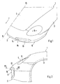
- a motor vehicle 1 in the bow region 2 shown comprises a side part 3, a hood 4, a headlight 5 and a bumper 6.
- the bumper 6 is composed of a transverse rigid support 7 and an elastic, the end portion of the Construction forming panel 8 together.
- the transverse beam 7 is gem.
- FIG. 3 held in place by means of hydraulic dampers 9 on the body.
- each receiving pocket 10 In laterally outer areas of the panel 8 are niche-shaped to the front open receiving pockets 10 are provided, with each receiving pocket 10 at least one lamp 11 inserted and on the panel 8 by screws, Clip or the like is held in position.
- Each lamp 11 comprises a housing 12 and on the side facing the end region a translucent cover element 13.
- the cover element 13 is not a Permanently elastic adhesive shown in detail connected to the housing 12.
- Each lamp 11 comprises a turn signal and / or a fog lamp and / or a Position light or the like.
- each light 11 extends on both sides of a center line A-A of the damper 9 running in the longitudinal direction of the vehicle.
- a - seen in plan view - is on each cover element 13 horn slightly protruding from the contour of the adjacent cladding 8 14 is provided, which is integrally formed with the cover member 13.
- the Covering element 13 is supported in the area of the horn 14 when the shock is impacted Bumper 6 on a underlying support structure (rigid support 7) of the Construction from.
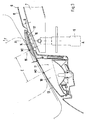
- the translucent cover member 13 and the horn 14 are made of one impact-resistant plastic, such as polycarbonate or the like. To be a good one To achieve the introduction of force into the structure, the horn 14 is on one Edge region 15 of the cover element 13 facing the vehicle longitudinal center plane B-B arranged (Fig. 3).
- Fig. 3 is the pendulum in continuous lines when hitting the Vehicle shown, with the point M1 the theoretical point of impact on the body represents.
- the position of the pendulum is in dash-dotted lines with an arrangement without horn shown with the theoretical point of impact M2, which is further outside than that Impact point M1.
- the cover element 13 lies in the area of the projecting horn 14 with its rear side 16 on the housing 12 or on a wall of the receiving pocket 10 of the casing 8 on.
- the cladding 8 is moved a short distance (gap G) moves backwards and is then supported directly on the rigid support 7 (not shown in more detail).
- the horn 14 extends over the entire height of the cover member 13, the Horn 14 - seen in a vertical section - is straight or curved. The integration of the horn 14 into the cover element 13 makes it virtually invisible Horn 14 created.
- the cladding 8 is in the area of the horn 14 on the wearer 7 facing side with a tilt 17.
Landscapes
- Engineering & Computer Science (AREA)
- Mechanical Engineering (AREA)
- Lighting Device Outwards From Vehicle And Optical Signal (AREA)
- Fittings On The Vehicle Exterior For Carrying Loads, And Devices For Holding Or Mounting Articles (AREA)
- Vehicle Interior And Exterior Ornaments, Soundproofing, And Insulation (AREA)
- Vibration Dampers (AREA)
- Body Structure For Vehicles (AREA)
Abstract
Description
- Fig. 1
- eine perspektivische Teilansicht von schräg vorne auf den Bugbereich eines Fahrzeuges,
- Fig. 2
- eine Teilseitenansicht des Bugbereiches,
- Fig. 3
- einen Horizontalschnitt gem. der Linie III-III der Fig. 2.
Claims (5)
- Stoßfänger für Fahrzeuge, insbesondere Kraftfahrzeuge, der einen formsteifen Träger und eine den Endbereich des Aufbaues bildende elastische Verkleidung umfaßt, wobei in seitlich außenliegende Aufnahmetaschen der Verkleidung jeweils zumindest eine Leuchte eingesetzt und an der Verkleidung in Lage gehalten ist und die Leuchte auf der dem Endbereich zugewandten Seite ein lichtdurchlässiges Abdeckelement aufweist, dadurch gekennzeichnet, daß an jedem Abdeckelement (13) örtlich ein gegenüber der angrenzenden elastischen Verkleidung (8) geringfügig vorstehendes, einstückig mit dem Abdeckelement (13) ausgebildetes Horn (14) vorgesehen ist und daß das Abdeckelement (13) im Bereich des Horns (14) bei einem 30° Pendelcrash an einer dahinterliegenden Trägerstruktur (7) des Aufbaues abgestützt ist.
- Stoßfänger nach Anspruch 1, dadurch gekennzeichnet, daß das lichtdurchlässige Abdeckelement (13) und das Horn (14) aus schlagfestem Kunststoff wie Polycarbonat hergestellt sind.
- Stoßfänger nach den Ansprüchen 1 und 2, dadurch gekennzeichnet, daß das Horn (14) an einem einer Fahrzeuglängsmittelebene (B-B) zugekehrten Randbereich (15) des Abdeckelements (13) angeordnet ist.
- Stoßfänger nach Anspruch 3, dadurch gekennzeichnet, daß das Horn (14) in Fahrtrichtung (F) gesehen einen konvexen Formverlauf aufweist.
- Stoßfänger nach einem der vorangegangenen Ansprüche, dadurch gekennzeichnet, daß durch die Anordnung des Horns (14) am innenliegenden Randbereich (15) des Abdeckelements (13) der theoretische Auftreffpunkt eines 30° Pendels nach innen in Richtung Fahrzeuglängsmittelebene (B-B) verlagert wird.
Applications Claiming Priority (2)
| Application Number | Priority Date | Filing Date | Title |
|---|---|---|---|
| DE10221294A DE10221294B4 (de) | 2002-05-14 | 2002-05-14 | Stoßfänger für Fahrzeuge, insbesondere Kraftfahrzeuge |
| DE10221294 | 2002-05-14 |
Publications (3)
| Publication Number | Publication Date |
|---|---|
| EP1362746A2 true EP1362746A2 (de) | 2003-11-19 |
| EP1362746A3 EP1362746A3 (de) | 2004-02-11 |
| EP1362746B1 EP1362746B1 (de) | 2006-02-15 |
Family
ID=29265266
Family Applications (1)
| Application Number | Title | Priority Date | Filing Date |
|---|---|---|---|
| EP03005869A Expired - Lifetime EP1362746B1 (de) | 2002-05-14 | 2003-03-15 | Stossfänger für Fahrzeuge, insbesondere Kraftfahrzeuge |
Country Status (4)
| Country | Link |
|---|---|
| US (1) | US6802547B2 (de) |
| EP (1) | EP1362746B1 (de) |
| DE (2) | DE10221294B4 (de) |
| ES (1) | ES2254806T3 (de) |
Families Citing this family (3)
| Publication number | Priority date | Publication date | Assignee | Title |
|---|---|---|---|---|
| US7740294B2 (en) * | 2006-11-16 | 2010-06-22 | Ronny Malina | Protective vehicle cover |
| US7823938B2 (en) | 2008-10-17 | 2010-11-02 | Honda Motor Co., Ltd. | Bumper faceplate with ports |
| US20100276951A1 (en) * | 2009-04-30 | 2010-11-04 | Ronny Malina | Automobile protector |
Family Cites Families (12)
| Publication number | Priority date | Publication date | Assignee | Title |
|---|---|---|---|---|
| DE2229782A1 (de) * | 1972-06-19 | 1974-01-10 | Volkswagenwerk Ag | Fahrzeug, insbesondere kraftfahrzeug, mit einem aus gummi oder kunststoff bestehenden karosserie-endbereich |
| US3836188A (en) * | 1973-04-25 | 1974-09-17 | Gen Motors Corp | Vehicle bumper system |
| DE2542920C3 (de) * | 1975-09-26 | 1979-10-25 | Dr.Ing.H.C. F. Porsche Ag, 7000 Stuttgart | Stoßfänger für Fahrzeuge, insbesondere Kraftfahrzeuge |
| US4213644A (en) * | 1978-08-17 | 1980-07-22 | Mccord Corporation | Energy-absorbing bumper assembly |
| JP2605891B2 (ja) * | 1989-10-20 | 1997-04-30 | 日産自動車株式会社 | バンパフェイシアの取付構造 |
| DE4136507A1 (de) * | 1990-11-16 | 1992-05-21 | Volkswagen Ag | Stossfaengeranordnung |
| DE4142582A1 (de) * | 1991-12-21 | 1993-06-24 | Porsche Ag | Stossfaenger fuer fahrzeuge, insbesondere kraftfahrzeuge |
| JPH08192699A (ja) * | 1995-01-20 | 1996-07-30 | Mitsubishi Motors Corp | ランプ類のバンパへの取付構造 |
| JP3319298B2 (ja) * | 1996-08-27 | 2002-08-26 | 三菱自動車工業株式会社 | バンパフェースの構造 |
| US6511109B1 (en) * | 2000-03-10 | 2003-01-28 | Plastech Engineered Products, Inc. | Bumper system for an automotive vehicle |
| DE10107287A1 (de) * | 2001-02-16 | 2002-09-12 | Porsche Ag | Stoßfängersystem für ein Fahrzeug |
| US6419289B1 (en) * | 2001-05-18 | 2002-07-16 | The Boler Company | Vehicle bumper system |
-
2002
- 2002-05-14 DE DE10221294A patent/DE10221294B4/de not_active Expired - Fee Related
-
2003
- 2003-03-15 DE DE50302392T patent/DE50302392D1/de not_active Expired - Lifetime
- 2003-03-15 ES ES03005869T patent/ES2254806T3/es not_active Expired - Lifetime
- 2003-03-15 EP EP03005869A patent/EP1362746B1/de not_active Expired - Lifetime
- 2003-05-07 US US10/430,288 patent/US6802547B2/en not_active Expired - Lifetime
Also Published As
| Publication number | Publication date |
|---|---|
| EP1362746B1 (de) | 2006-02-15 |
| DE50302392D1 (de) | 2006-04-20 |
| US20030214138A1 (en) | 2003-11-20 |
| DE10221294B4 (de) | 2004-08-26 |
| EP1362746A3 (de) | 2004-02-11 |
| ES2254806T3 (es) | 2006-06-16 |
| DE10221294A1 (de) | 2003-12-04 |
| US6802547B2 (en) | 2004-10-12 |
Similar Documents
| Publication | Publication Date | Title |
|---|---|---|
| DE60111878T2 (de) | Scheinwerfereinrichtung für Fahrzeuge | |
| DE10237454B3 (de) | Frontend-Modul für ein Kraftfahrzeug | |
| DE3108059A1 (de) | "streuscheibe fuer scheinwerfer von fahrzeugen" | |
| DE102005031843B4 (de) | Vorderwagenstruktur eines Kraftfahrzeuges | |
| DE102020115446A1 (de) | Ziergitter für fahrzeugfront | |
| DE10258629B4 (de) | Fahrzeug | |
| DE10030373A1 (de) | Befestigungsvorrichtung für einen Kraftfahrzeugscheinwerfer | |
| DE60025065T2 (de) | Einbau einer optischen Einheit auf Karosserieteile eines Fahrzeugs | |
| DE102012210444A1 (de) | Leuchte, insbesondere Fahrzeugleuchte | |
| DE10062735A1 (de) | Beleuchtungseinrichtung, insbesondere Scheinwerfer oder Scheinwerferleuchteneinheit für Kraftfahrzeuge | |
| EP1362746A2 (de) | Stossfänger für Fahrzeuge, insbesondere Kraftfahrzeuge | |
| WO2005058640A1 (de) | Fahrzeug-beleuchtungseinrichtung | |
| DE102020104247A1 (de) | Trägervorrichtung eines frontendmoduls sowie fahrzeug mit einer trägervorrichtung | |
| DE10305652A1 (de) | Frontendbereich | |
| DE10101794A1 (de) | Beleuchtungseinrichtung, insbesondere Scheinwerfer oder Scheinwerferleuchteneinheit, für Kraftfahrzeuge | |
| DE602005003976T2 (de) | Kraftfahrzeugkarosserie-Kotflügel aus Kunststoff mit einer Indexierungsvorrichtung | |
| EP2248704A2 (de) | Frontklappe für Kraftfahrzeuge | |
| DE10350294A1 (de) | Kühlergrillanordnung für ein Kraftfahrzeug | |
| DE3035352A1 (de) | Vorderer kraftfahrzeug-endbereich | |
| DE102004057473B4 (de) | Elastisches Kühlergitter | |
| DE3339141A1 (de) | Fest einsetzbare vordere seitenscheibe fuer kraftfahrzeuge | |
| EP0255139B1 (de) | Kraftfahrzeug, insbesondere Personenkraftwagen, mit in die flach verlaufende Fahrzeugbugdeckwand eingelassen angeordneten Scheinwerfern | |
| DE4439910B4 (de) | Kraftfahrzeugscheinwerferanordnung | |
| DE102024109603A1 (de) | Scheinwerfervorrichtung für ein Kraftfahrzeug und Kraftfahrzeug | |
| DE696491C (de) | Rueckstrahler, insbesondere fuer Fahrraeder |
Legal Events
| Date | Code | Title | Description |
|---|---|---|---|
| PUAI | Public reference made under article 153(3) epc to a published international application that has entered the european phase |
Free format text: ORIGINAL CODE: 0009012 |
|
| AK | Designated contracting states |
Kind code of ref document: A2 Designated state(s): AT BE BG CH CY CZ DE DK EE ES FI FR GB GR HU IE IT LI LU MC NL PT RO SE SI SK TR |
|
| AX | Request for extension of the european patent |
Extension state: AL LT LV MK |
|
| PUAL | Search report despatched |
Free format text: ORIGINAL CODE: 0009013 |
|
| AK | Designated contracting states |
Kind code of ref document: A3 Designated state(s): AT BE BG CH CY CZ DE DK EE ES FI FR GB GR HU IE IT LI LU MC NL PT RO SE SI SK TR |
|
| AX | Request for extension of the european patent |
Extension state: AL LT LV MK |
|
| RIC1 | Information provided on ipc code assigned before grant |
Ipc: 7B 60R 19/50 A Ipc: 7B 60Q 1/04 B |
|
| 17P | Request for examination filed |
Effective date: 20040811 |
|
| AKX | Designation fees paid |
Designated state(s): DE ES FR GB IT |
|
| GRAP | Despatch of communication of intention to grant a patent |
Free format text: ORIGINAL CODE: EPIDOSNIGR1 |
|
| GRAS | Grant fee paid |
Free format text: ORIGINAL CODE: EPIDOSNIGR3 |
|
| GRAA | (expected) grant |
Free format text: ORIGINAL CODE: 0009210 |
|
| AK | Designated contracting states |
Kind code of ref document: B1 Designated state(s): DE ES FR GB IT |
|
| REG | Reference to a national code |
Ref country code: GB Ref legal event code: FG4D Free format text: NOT ENGLISH |
|
| REF | Corresponds to: |
Ref document number: 50302392 Country of ref document: DE Date of ref document: 20060420 Kind code of ref document: P |
|
| GBT | Gb: translation of ep patent filed (gb section 77(6)(a)/1977) |
Effective date: 20060405 |
|
| REG | Reference to a national code |
Ref country code: ES Ref legal event code: FG2A Ref document number: 2254806 Country of ref document: ES Kind code of ref document: T3 |
|
| ET | Fr: translation filed | ||
| PLBE | No opposition filed within time limit |
Free format text: ORIGINAL CODE: 0009261 |
|
| STAA | Information on the status of an ep patent application or granted ep patent |
Free format text: STATUS: NO OPPOSITION FILED WITHIN TIME LIMIT |
|
| 26N | No opposition filed |
Effective date: 20061116 |
|
| PGFP | Annual fee paid to national office [announced via postgrant information from national office to epo] |
Ref country code: ES Payment date: 20080328 Year of fee payment: 6 |
|
| REG | Reference to a national code |
Ref country code: FR Ref legal event code: TP |
|
| REG | Reference to a national code |
Ref country code: FR Ref legal event code: CD |
|
| REG | Reference to a national code |
Ref country code: ES Ref legal event code: FD2A Effective date: 20090316 |
|
| PG25 | Lapsed in a contracting state [announced via postgrant information from national office to epo] |
Ref country code: ES Free format text: LAPSE BECAUSE OF NON-PAYMENT OF DUE FEES Effective date: 20090316 |
|
| REG | Reference to a national code |
Ref country code: FR Ref legal event code: TP |
|
| REG | Reference to a national code |
Ref country code: GB Ref legal event code: 732E Free format text: REGISTERED BETWEEN 20110310 AND 20110316 |
|
| REG | Reference to a national code |
Ref country code: GB Ref legal event code: 732E Free format text: REGISTERED BETWEEN 20110331 AND 20110406 |
|
| REG | Reference to a national code |
Ref country code: FR Ref legal event code: PLFP Year of fee payment: 13 |
|
| PGFP | Annual fee paid to national office [announced via postgrant information from national office to epo] |
Ref country code: IT Payment date: 20150327 Year of fee payment: 13 Ref country code: DE Payment date: 20150304 Year of fee payment: 13 |
|
| PGFP | Annual fee paid to national office [announced via postgrant information from national office to epo] |
Ref country code: GB Payment date: 20150319 Year of fee payment: 13 Ref country code: FR Payment date: 20150319 Year of fee payment: 13 |
|
| REG | Reference to a national code |
Ref country code: DE Ref legal event code: R119 Ref document number: 50302392 Country of ref document: DE |
|
| GBPC | Gb: european patent ceased through non-payment of renewal fee |
Effective date: 20160315 |
|
| REG | Reference to a national code |
Ref country code: FR Ref legal event code: ST Effective date: 20161130 |
|
| PG25 | Lapsed in a contracting state [announced via postgrant information from national office to epo] |
Ref country code: GB Free format text: LAPSE BECAUSE OF NON-PAYMENT OF DUE FEES Effective date: 20160315 Ref country code: FR Free format text: LAPSE BECAUSE OF NON-PAYMENT OF DUE FEES Effective date: 20160331 Ref country code: DE Free format text: LAPSE BECAUSE OF NON-PAYMENT OF DUE FEES Effective date: 20161001 |
|
| PG25 | Lapsed in a contracting state [announced via postgrant information from national office to epo] |
Ref country code: IT Free format text: LAPSE BECAUSE OF NON-PAYMENT OF DUE FEES Effective date: 20160315 |