EP1362743A1 - Roof carrier system for a vehicle, method of manufacturing the roof carrier system and vehicle with a roof carrier system - Google Patents
Roof carrier system for a vehicle, method of manufacturing the roof carrier system and vehicle with a roof carrier system Download PDFInfo
- Publication number
- EP1362743A1 EP1362743A1 EP03010993A EP03010993A EP1362743A1 EP 1362743 A1 EP1362743 A1 EP 1362743A1 EP 03010993 A EP03010993 A EP 03010993A EP 03010993 A EP03010993 A EP 03010993A EP 1362743 A1 EP1362743 A1 EP 1362743A1
- Authority
- EP
- European Patent Office
- Prior art keywords
- roof
- rack system
- strip
- vehicle body
- vehicle
- Prior art date
- Legal status (The legal status is an assumption and is not a legal conclusion. Google has not performed a legal analysis and makes no representation as to the accuracy of the status listed.)
- Granted
Links
Images


Classifications
-
- B—PERFORMING OPERATIONS; TRANSPORTING
- B60—VEHICLES IN GENERAL
- B60R—VEHICLES, VEHICLE FITTINGS, OR VEHICLE PARTS, NOT OTHERWISE PROVIDED FOR
- B60R9/00—Supplementary fittings on vehicle exterior for carrying loads, e.g. luggage, sports gear or the like
- B60R9/04—Carriers associated with vehicle roof
Definitions
- the invention relates to a roof rack system for a Vehicle, in particular for a passenger car.
- Passenger cars can on their roof a roof rack system in the form of a roof rail, made of two parallel roof rails exist, own. These roof rails can be one or be designed in several parts. Roof rails, which are designed in three or more parts, have at least one middle part and two with the middle part assembled end parts on. The two End pieces are at a distance to the roof surface of the Vehicle-generating foot struts provided. A corresponding footstay is in the middle area arranged the middle part.
- the famous roof rails has proven itself and gives the vehicle a characteristic Appearance.
- the invention is concerned with a novel Construction of a roof rack system with the one special, optical effect goes along.
- At least one roof strip is provided, the one essentially continuous the vehicle body auflegbare, about the Length of the roof rail extending, the vehicle body having adapted support surface.
- the specially trained contact surface of the foot strut-free Construction towers over the roof strip Vehicle roof only at about the height of the strip high-precision fit to the vehicle body contour, in particular to the side wall frames of the motor vehicle, on which the roof rails are mountable.
- the high accuracy results from the adapted Investment surface, that is, this is designed in such a way that it corresponds to the vehicle body contour and consequently a uniform marginal gap formation between roof rail and vehicle body leads, so no covering means, such as Example bordering gums or the like used Need to become.
- the contact surface is a by reworking adapted contact surface is.
- This post-processing for example, one after the bend the roof strip takes place machining be on the roof rail to the one by the bend
- the vehicle body series contour produced only approximate Contour the actual vehicle body contour to give.
- This scattering in the bending contour is even with the most careful processing unavoidable and are therefore preferred corrected in the above way.
- the mentioned uniform marginal gap formation can be made such that in particular the outer, the vehicle body associated edge rests directly on the vehicle roof, ie a gap width of the dimension zero is present.
- gap zero can also be a minimum gap be provided.
- the minimum gap or a big gap can go hand in hand with the features that the contact surface configured and arranged is that at least the outer, the vehicle body assigned edge of the roof rail with the vehicle body, so with the vehicle roof, forms a shadow gap.
- To produce the Shadow gap is a distance of the marginal edge of the Roof rail to the vehicle body required, the due to the invention at any point the same size or almost the same size.
- shadow gap can optionally be used as a rubbing strip clear plastic film be provided.
- the mentioned shadow gap is preferable thereby generate that the contact surface at least a support web is formed.
- the vehicle body facing side has the Roof strip accordingly the at least one support web in particular in one piece, in particular narrower than the bar is and therefore not extends to the edge of the roof strip, but is reset.
- This can be on the outside and alternatively or additionally on the inner Side of the roof rail to be the case, taking under outer edge is to understand the marginal edge, the a passerby standing next to the vehicle sees.
- the inboard, so more to the vehicle center oriented edge of the roof rail can also with uniform marginal gap formation and / or Shadow joint be formed, however, is of one Passers-by not immediately because of their location insightful.
- roof rail reset support bar creates an optical Floating effect of the roof rail, because not directly recognizable is how they are on the vehicle roof is held.
- several can Supports be provided, for example, parallel lying to each other, in the longitudinal direction of the bar running, relatively thin-walled webs.
- the roof strip is designed as a hollow profile is.
- an extruded profile can be used become.
- the roof bar As a material for the roof bar come in particular Aluminum, magnesium, steel and / or brass, as well their alloys in question, the use of Aluminum is preferred and therefore the possibility is given to the surface after polishing anodising. Alternatively, however, it can also be independent of the material used - a surface coating, in particular a powder or Paint coating or chrome plating, be made.
- the roof strip is preferably formed in one piece, that is, regardless of possible fasteners lies a one-piece design which includes the middle part and also the forehead parts.
- a multi-piece training be provided, which has a middle part and two with having the middle part connectable end parts.
- the middle part as a hollow profile, in particular as Extruded hollow profile can be configured and the forehead parts as forgings, especially at made of aluminum can.
- the end pieces can also as milled or trimmed profile pieces formed be. If a surface coating, so is It also possible to use the end pieces as injection molded parts manufacture. Should anodization be made of aluminum existing roof rail are made, so consists of the middle part of aluminum tube and the End pieces are manufactured as aluminum forgings.
- the invention relates to a Method for producing a roof rack system, wherein in the integral formation of the roof rail this according to the vehicle body contour bent and then the contact surface by one taking into account the vehicle body contour Processing, in particular post-processing, preferably machining, is generated.
- the invention is further characterized by a Method for producing a roof rack system, wherein in Inc. training of the roof rail the middle part corresponding to the vehicle body contour bent, then the middle part of the two Are assigned to end shares and that subsequently the contact surface by one, the vehicle body contour considering processing, in particular Post-processing, preferably machining, is produced. Further advantages of the process emerge from the dependent claims.
- the invention relates to a vehicle, in particular Passenger cars, with a roof rack system according to of the claims.
- the invention with a vehicle concerns at least one roof strip, wherein the Motor vehicle body, in particular each sidewall frame of the motor vehicle, at least one channel-shaped Deepening has a roof molding partially absorbed in the area of their contact surface.
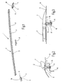
- FIG. 1 shows a roof rack system 1 for the Roof of a motor vehicle.
- the roof rack system 1 has a roof strip 2, which is a middle part. 3 and two end parts 4 includes.
- the middle part 3 is a separate fastener 5 can be assigned.
- two such roof strips 2 are the Roof of a motor vehicle assigned, preferably such that each side wall frame 6 of the motor vehicle each has a roof strip 2 (FIG 2).
- the middle part 3 is as a hollow profile 7, in particular Extruded profile 8, formed of aluminum.
- ends 9 formed as aluminum forgings 10 are.
- the two aluminum forgings 10 each have spigot 11, which in the Interior of the hollow section 7 inserted and in addition by gluing, pressing, screwing, grooving or pinning secured.
- the surface of the middle part 3 and the two end parts 4 polished and anodized trained.
- a front part 4 in Cross-section or in longitudinal section show are the two end parts 4 also with fasteners 5 in the form of integrally formed Threaded bushings 12 provided.
- fasteners 5 for mounting on the Vehicle body 13, in particular the side wall frame 6, are threaded from the vehicle inside 14 uses a mounting hole 15th a holding plate 16 of the vehicle pass through and are screwed into an intermediate part 17, which in turn each bolted to the threaded bushing 12 is.
- By tightening the screws 14 leaves the roof strip 2 in the region of their end parts 4 on the vehicle roof.
- the middle part 3 by means of this associated Secured fastener 5. details this will be apparent from Figures 4 and 5.
- the T-shaped fastener 5 with two legs 18 in the Interior of the hollow section 7 engages and glued there, grooved, pressed, screwed or pinned is.
- a vertical web 19 of the fastener 5 has a threaded bore 20 in the a threaded screw 21 is screwed, the one Attachment hole 22 of a holding plate 23 of the vehicle passes through, causing the roof strip 2 in their middle area with their bottom 24 firmly on the vehicle body 13, in particular is pulled on the side wall frame 6.
- both the middle part 3 and to the front parts 4 support webs 25 integrally formed, extending over the entire longitudinal extent extend the roof rail 2.
- the roof strip 2 With the parallel spaced apart support webs 25th is the roof strip 2 on the vehicle body 13, wherein as a support in the area of the support webs 25 a scuff protection 26 in the form of a clear plastic film can be applied.
- the individual support webs 25 form at their the vehicle facing side a total investment area 27 off, over the entire longitudinal extent of the Roof strip runs and the vehicle body contour -in the longitudinal extent of the roof molding 2 seen fit is.
- This adjustment is achieved by that after the extrusion of the middle part 3 of this bent according to the vehicle body contour or stretch bent.
- the arch form is due the roof vault is required and is of the respective Vehicle type dependent.
- the bow curvature is relatively low, so that these from the figure 1 not immediately apparent. Only by creating a Lineals becomes clear that the middle part 3 and also the associated end parts 4 at their respective Underside have a slight curvature.
- a post-treatment is made, in particular a machining, such that vehicle body contour and the contour of the contact surface 27, formed on the undersides of the support webs 25, match, leaving the roof bar 2 are accurately assigned to the vehicle can without different-seen over the length Set gap dimensions (arrow 28, 29).
- the arrangement is preferably made in such a way that the outer peripheral edge 30 of the roof rail 2 for Vehicle body 13 a uniform distance, in particular minimal gap to form a Shadow gap 31 complies.
- the first a greater height than the out Figure 6 resulting height h having support webs 25 are by the mentioned post (machining, in particular milling), so far shortened, that the mentioned adapted Situation is created. It can-over the length seen the roof strip 2 - depending on the bending state of Roof strip 2 different amounts of material from the Auflagestegen 25 have been removed.
- the above Procedure can also be carried out accordingly be, if the roof rail no support webs having. It then lies with its lower wall flat on the compartment roof. The optionally subsequent editing then sees one machining the lower wall in front.
- FIG. 7 shows an embodiment which is shown in FIG Essentially the embodiment of Figure 6 corresponds, except that the vehicle body 13 in Area of the bottom 24 of the roof rail 2 a groove-shaped recess 32, which is the roof strip 2 in the region of their contact surface 27 in regions receives.
- the contact surface 27 is hidden and consequently, the peripheral edge 30 of the roof rail 2 deprived of the view of the beholder.
- a uneven gap formation of the roof strip 2 via their longitudinal extent relative to the vehicle body 13 is therefore laminated, although the inventive adaptation of the contact surface to the Car body is performed and consequently even in the not immediately obvious area a uniform edge gap training performed is.
- FIGS. 8 to 12 show a further embodiment a roof rail 2, also is formed in three parts.
- FIGS. 8 to 12 largely correspond to Figures 1 to 5, wherein only discussed the differences below shall be. These are that it at the end portions 4 of the embodiment Figures 8 to 12 are not forgings, ie Full parts, but deals with hollow parts, therefore no integrally formed with them fasteners 5 have.
- trained end pieces 4 are therefore L-shaped Fastening elements 5 used, wherein the one Leg 34 of each fastener 5 -so like the legs 18 of the middle fastener 5- glued to the associated hollow part become. That is, the legs 34 are connected to the glued corresponding end portions 4.
- each the end portions 4 associated fasteners 5 also has a vertical web 36 on, -esammlung as the vertical web 19 of the middle fastener 5 with threaded hole 20 is provided, in which a threaded screw 21 is screwed in to laying down at the Vehicle body and thus the pressing on the Vehicle roof to ensure ( Figures 9 and 10).
Abstract
Description
Die Erfindung betrifft ein Dachträgersystem für ein Fahrzeug, insbesondere für einen Personenkraftwagen.The invention relates to a roof rack system for a Vehicle, in particular for a passenger car.
Personenkraftwagen können auf ihrem Dach ein Dachträgersystem in Form einer Dachreling, die aus zwei, parallel zueinander angeordneten Dachschienen bestehen, besitzen. Diese Dachschienen können einoder mehrteilig gestaltet sein. Dachschienen, welche drei- oder mehrteilig gestaltet sind, weisen mindestens ein Mittelteil sowie zwei mit dem Mittelteil zusammengesteckte Endteile auf. Die beiden Endteile sind mit einen Abstand zur Dachfläche des Fahrzeugs erzeugenden Fußstreben versehen. Eine entsprechende Fußstrebe ist im mittleren Bereich des Mittelteils angeordnet. Die bekannte Dachreling hat sich bewährt und gibt dem Fahrzeug ein charakteristisches Aussehen.Passenger cars can on their roof a roof rack system in the form of a roof rail, made of two parallel roof rails exist, own. These roof rails can be one or be designed in several parts. Roof rails, which are designed in three or more parts, have at least one middle part and two with the middle part assembled end parts on. The two End pieces are at a distance to the roof surface of the Vehicle-generating foot struts provided. A corresponding footstay is in the middle area arranged the middle part. The famous roof rails has proven itself and gives the vehicle a characteristic Appearance.
Die Erfindung befasst sich mit einer neuartigen Konstruktion eines Dachträgersystems mit dem ein besonderer, optischer Effekt einhergeht.The invention is concerned with a novel Construction of a roof rack system with the one special, optical effect goes along.
Erfindungsgemäß ist mindestens eine Dachleiste vorgesehen, die eine im Wesentlichen durchgängig auf die Fahrzeugkarosserie auflegbare, sich über die Länge der Dachleiste erstreckende, der Fahrzeugkarosserie angepasste Auflagefläche aufweist. Durch die speziell ausgebildete Anlagefläche der fußstrebenfreien Konstruktion überragt die Dachleiste das Fahrzeugdach nur etwa in Höhe der Leistendicke bei hochgenauem Passsitz zur Fahrzeugkarosseriekontur, insbesondere zu den Seitenwandrahmen des Kraftfahrzeugs, auf denen die Dachleisten montierbar sind. Die hohe Genauigkeit resultiert aus der angepassten Anlagefläche, das heißt, diese ist derart gestaltet, dass sie der Fahrzeugkarosseriekontur entspricht und demzufolge zu einer gleichmäßigen Randspaltausbildung zwischen Dachleiste und Fahrzeugkarosserie führt, so dass keine Abdeckmittel, wie zum Beispiel Einfassgummis oder dergleichen eingesetzt werden müssen. Durch die Erfindung ist es vielmehr möglich, direkt auf dem Fahrzeugdach und dieses nur wenig überragende Dachleisten anzuordnen, die ferner zu ebenmäßigen und daher optisch sehr ansprechenden Randspalten führt. Durch das Anpassen der Anlagefläche an die Fahrzeugkarosseriekontur werden stets bei der Herstellung auftretende Toleranzen ausgeglichen. Diese Toleranzen betreffen die Konturierung der Dachschiene, die ihre Formgebung vorzugsweise durch einen Biegevorgang erhält. Da die Biegung aufgrund unterschiedlicher Einflussparameter jedoch nicht mit reproduzierbarer Genauigkeit möglich ist und daher Abweichungen unumgänglich sind, sorgt die angepasste Anlagefläche für einen optimalen Sitz, so dass Kaschiermaßnahmen, wie beispielsweise die erwähnten Gummieinfassungen oder Kunststoffeinfassungen, entfallen können.According to the invention, at least one roof strip is provided, the one essentially continuous the vehicle body auflegbare, about the Length of the roof rail extending, the vehicle body having adapted support surface. By the specially trained contact surface of the foot strut-free Construction towers over the roof strip Vehicle roof only at about the height of the strip high-precision fit to the vehicle body contour, in particular to the side wall frames of the motor vehicle, on which the roof rails are mountable. The high accuracy results from the adapted Investment surface, that is, this is designed in such a way that it corresponds to the vehicle body contour and consequently a uniform marginal gap formation between roof rail and vehicle body leads, so no covering means, such as Example bordering gums or the like used Need to become. Rather, it is by the invention possible, directly on the vehicle roof and this only To arrange little towering roof strips, the further to even and therefore visually appealing Edge columns leads. By adjusting the Be contact surface to the vehicle body contour always occurring during production tolerances balanced. These tolerances affect the contouring the roof rail, which prefers its shaping obtained by a bending process. Because the Bending due to different influencing parameters but not with reproducible accuracy is possible and therefore deviations inevitable the adjusted contact surface provides for one optimal fit, so laminating measures, such as the mentioned rubber mounts or Plastic enclosures, can be omitted.
Nach einer Weiterbildung der Erfindung ist vorgesehen, dass die Anlagefläche eine durch Nachbearbeitung angepasste Anlagefläche ist. Diese Nachbearbeitung kann beispielsweise eine nach der Biegung der Dachleiste erfolgende spanabhebende Bearbeitung an der Dachleiste sein, um der durch die Biegung erzeugten der Fahrzeugkarossseriekontur nur angenährten Kontur die tatsächliche Fahrzeugkarosseriekontur zu geben. Im Zuge der Fertigung werden -je nach Biegeergebnis- Abtragungsmaßnahmen des Schienenmaterials in unterschiedlichem Umfang bei verschiedenen Schienen stattfinden, obwohl die Schienen in ein und derselben Biegemaschine unter gleichen Bedingungen gebogen wurden. Diese Streuung in der Biegekontur ist selbst bei sorgfältigster Bearbeitung nicht zu vermeiden und werden daher bevorzugt in vorstehender Weise korrigiert.According to a development of the invention is provided that the contact surface is a by reworking adapted contact surface is. This post-processing for example, one after the bend the roof strip takes place machining be on the roof rail to the one by the bend The vehicle body series contour produced only approximate Contour the actual vehicle body contour to give. In the course of production -je after bending result removal measures of the rail material to varying degrees at different Rails take place, though the rails in one and the same bending machine under the same Conditions were bent. This scattering in the bending contour is even with the most careful processing unavoidable and are therefore preferred corrected in the above way.
Die erwähnte gleichmäßige Randspaltausbildung kann derart getroffen sein, dass insbesondere die äußere, der Fahrzeugkarosserie zugeordnete Randkante direkt auf dem Fahrzeugdach aufliegt, also eine Spaltbreite des Maßes Null vorliegt. Dies ungeachtet der Möglichkeit, dass unter der Dachleiste, also auf dem Fahrzeugdach, eine vorzugsweise dünne, durchsichtige Scheuerleiste (Klarsicht-Kunststofffolie) aufgeklebt ist, um einen Lackschutz zu gewährleisten. Alternativ zu dem Spaltmaß Null kann jedoch auch ein Minimal-Spalt vorgesehen sein. Der Minimal-Spalt oder auch ein großer Spalt kann mit den Merkmalen einhergehen, dass die Anlagefläche derart ausgestaltet und angeordnet ist, dass zumindest die äußere, der Fahrzeugkarosserie zugeordnete Randkante der Dachleiste mit der Fahrzeugkarosserie, also mit dem Fahrzeugdach, eine Schattenfuge bildet. Zur Erzeugung der Schattenfuge ist ein Abstand der Randkante der Dachleiste zur Fahrzeugkarosserie erforderlich, der aufgrund der Erfindung an jeder Stelle gleich groß oder nahezu gleich groß ist. Trotz Schattenfuge kann optional die als Scheuerleiste dienende Klarsicht-Kunststofffolie vorgesehen sein.The mentioned uniform marginal gap formation can be made such that in particular the outer, the vehicle body associated edge rests directly on the vehicle roof, ie a gap width of the dimension zero is present. This notwithstanding the possibility that under the roof bar, So on the vehicle roof, preferably thin, transparent rubbing strip (transparent plastic film) is glued to one To ensure paint protection. Alternatively to that However, gap zero can also be a minimum gap be provided. The minimum gap or a big gap can go hand in hand with the features that the contact surface configured and arranged is that at least the outer, the vehicle body assigned edge of the roof rail with the vehicle body, so with the vehicle roof, forms a shadow gap. To produce the Shadow gap is a distance of the marginal edge of the Roof rail to the vehicle body required, the due to the invention at any point the same size or almost the same size. Despite shadow gap can optionally be used as a rubbing strip clear plastic film be provided.
Die erwähnte Schattenfuge lässt sich vorzugsweise dadurch erzeugen, dass die Anlagefläche an mindestens einem Auflagesteg ausgebildet ist. An ihrer, der Fahrzeugkarosserie zugekehrten Seite weist die Dachleiste demgemäss den mindestens einen Auflagesteg insbesondere einstückig auf, der insbesondere schmaler als die Leiste ist und demzufolge nicht bis zur Randkante der Dachleiste reicht, sondern zurückgesetzt liegt. Dies kann auf der äußeren und alternativ oder zusätzlich auch auf der inneren Seite der Dachleiste der Fall sein, wobei unter äußerer Kante die Randkante zu verstehen ist, die ein neben dem Fahrzeug stehender Passant sieht. Die innenliegende, also mehr zur Fahrzeuglängsmitte orientierte Randkante der Dachleiste kann ebenfalls mit gleichmäßiger Randspaltausbildung und/oder Schattenfuge ausgebildet sein, ist jedoch von einem Passanten aufgrund ihrer Lage nicht unmittelbar einsichtig. Der gegenüber der Randkante der Dachleiste rückgesetzte Auflagesteg erzeugt einen optischen Schwebeeffekt der Dachleiste, da nicht unmittelbar erkennbar ist, wie sie auf dem Fahrzeugdach gehalten wird. Insbesondere können mehrere Auflagestege vorgesehen sein, beispielsweise parallel zueinanderliegende, in Längsrichtung der Leiste verlaufende, relativ dünnwandige Stege. The mentioned shadow gap is preferable thereby generate that the contact surface at least a support web is formed. At her, the vehicle body facing side has the Roof strip accordingly the at least one support web in particular in one piece, in particular narrower than the bar is and therefore not extends to the edge of the roof strip, but is reset. This can be on the outside and alternatively or additionally on the inner Side of the roof rail to be the case, taking under outer edge is to understand the marginal edge, the a passerby standing next to the vehicle sees. The inboard, so more to the vehicle center oriented edge of the roof rail can also with uniform marginal gap formation and / or Shadow joint be formed, however, is of one Passers-by not immediately because of their location insightful. The opposite the edge of the roof rail reset support bar creates an optical Floating effect of the roof rail, because not directly recognizable is how they are on the vehicle roof is held. In particular, several can Supports be provided, for example, parallel lying to each other, in the longitudinal direction of the bar running, relatively thin-walled webs.
Nach einer Weiterbildung der Erfindung ist vorgesehen, dass die Dachleiste als Hohlprofil ausgebildet ist. Insbesondere kann ein Strangpressprofil eingesetzt werden.According to a development of the invention is provided that the roof strip is designed as a hollow profile is. In particular, an extruded profile can be used become.
Als Material für die Dachleiste kommen insbesondere Aluminium, Magnesium, Stahl und/oder Messing, sowie deren Legierungen in Frage, wobei der Einsatz von Aluminium bevorzugt ist und daher die Möglichkeit gegeben wird, die Oberfläche nach dem Polieren zu eloxieren. Alternativ kann jedoch auch -unabhängig vom eingesetzten Material- eine Oberflächenbeschichtung, insbesondere eine Pulver- beziehungsweise Lackierbeschichtung oder eine Verchromung, vorgenommen werden.As a material for the roof bar come in particular Aluminum, magnesium, steel and / or brass, as well their alloys in question, the use of Aluminum is preferred and therefore the possibility is given to the surface after polishing anodising. Alternatively, however, it can also be independent of the material used - a surface coating, in particular a powder or Paint coating or chrome plating, be made.
Die Dachleiste ist bevorzugt einstückig ausgebildet, das heißt, unabhängig von möglichen Befestigungsmitteln liegt eine einstückige Ausgestaltung vor, die das Mittelteil und auch die Stirnteile umfasst. Alternativ kann eine mehrstückige Ausbildung vorgesehen sein, die ein Mittelteil und zwei mit dem Mittelteil verbindbare Stirnteile aufweist. Mithin liegt eine dreiteilige Struktur vor, wobei das Mittelteil als Hohlprofil, insbesondere als Strangpress-Hohlprofil ausgestaltet sein kann und die Stirnteile als Schmiedeteile, insbesondere bei der Herstellung aus Aluminium, gefertigt werden können. Alternativ können die Stirnteile auch als gefräste oder beschnittene Profilstücke ausgebildet sein. Erfolgt eine Oberflächenbeschichtung, so ist es auch möglich, die Stirnteile als Spritzgussteile herzustellen. Soll eine Eloxierung einer aus Aluminium bestehenden Dachleiste vorgenommen werden, so besteht das Mittelteil aus Aluminiumrohr und die Stirnteile sind als Aluminiumschmiedeteile gefertigt.The roof strip is preferably formed in one piece, that is, regardless of possible fasteners lies a one-piece design which includes the middle part and also the forehead parts. Alternatively, a multi-piece training be provided, which has a middle part and two with having the middle part connectable end parts. Thus, there is a three-part structure, wherein the middle part as a hollow profile, in particular as Extruded hollow profile can be configured and the forehead parts as forgings, especially at made of aluminum can. Alternatively, the end pieces can also as milled or trimmed profile pieces formed be. If a surface coating, so is It also possible to use the end pieces as injection molded parts manufacture. Should anodization be made of aluminum existing roof rail are made, so consists of the middle part of aluminum tube and the End pieces are manufactured as aluminum forgings.
Weitere Vorteile der Erfindung ergeben sich aus den Unteransprüchen. Ferner betrifft die Erfindung ein Verfahren zur Herstellung eines Dachträgersystems, wobei bei der einstückigen Ausbildung der Dachleiste diese entsprechend der Fahrzeugkarosseriekontur gebogen und anschließend die Anlagefläche durch eine, die Fahrzeugkarosseriekontur berücksichtigende Bearbeitung, insbesondere Nachbearbeitung, bevorzugt spanende Bearbeitung, erzeugt wird. Die Erfindung ist ferner gekennzeichnet durch ein Verfahren zur Herstellung eines Dachträgersystems, wobei bei mehrstückiger Ausbildung der Dachleiste das Mittelteil entsprechend der Fahrzeugkarosseriekontur gebogen, dann dem Mittelteil die beiden Stirnteile zugeordnet werden und dass anschließend die Anlagefläche durch eine, die Fahrzeugkarosseriekontur berücksichtigende Bearbeitung, insbesondere Nachbearbeitung, bevorzugt spanende Bearbeitung, erzeugt wird. Weitere Vorteile des Verfahrens ergeben sich aus den Unteransprüchen. Schließlich betrifft die Erfindung ein Fahrzeug, insbesondere Personenkraftwagen, mit einem Dachträgersystem gemäß der Patentansprüche. Letztlich kann auch vorgesehen sein, dass die Erfindung ein Fahrzeug mit mindestens einer Dachleiste betrifft, wobei die Kraftfahrzeugkarosserie, insbesondere jeder Seitenwandrahmen des Kraftfahrzeugs, mindestens eine rinnenförmige Vertiefung aufweist, die eine Dachleiste im Bereich ihrer Anlagefläche teilweise aufnimmt. Further advantages of the invention will become apparent from the Dependent claims. Furthermore, the invention relates to a Method for producing a roof rack system, wherein in the integral formation of the roof rail this according to the vehicle body contour bent and then the contact surface by one taking into account the vehicle body contour Processing, in particular post-processing, preferably machining, is generated. The invention is further characterized by a Method for producing a roof rack system, wherein in mehrstückiger training of the roof rail the middle part corresponding to the vehicle body contour bent, then the middle part of the two Are assigned to end shares and that subsequently the contact surface by one, the vehicle body contour considering processing, in particular Post-processing, preferably machining, is produced. Further advantages of the process emerge from the dependent claims. After all The invention relates to a vehicle, in particular Passenger cars, with a roof rack system according to of the claims. Ultimately, can also be provided be that the invention with a vehicle concerns at least one roof strip, wherein the Motor vehicle body, in particular each sidewall frame of the motor vehicle, at least one channel-shaped Deepening has a roof molding partially absorbed in the area of their contact surface.
Die Zeichnungen veranschaulichen die Erfindung anhand von Ausführungsbeispielen, und zwar zeigt:
Figur 1- ein als Dachleiste ausgebildetes Dachträgersystem in dreiteiliger Form und Explosionsdarstellung,
Figur 2- einen Querschnitt durch ein Stirnteil der
Dachleiste gemäß
Figur 1, Figur 3- einen Längsschnitt durch eines der Stirnteile
und einen Abschnitt des Mittelteils
der Dachleiste der
Figur 1, Figur 4- einen Längsschnitt durch das Mittelteil der Dachleiste im Bereich eines Befestigungselements,
Figur 5- einen Querschnitt durch die Dachleiste im
Bereich des Befestigungselements gemäß
Figur 4, Figur 6- einen Querschnitt durch die Dachleiste
der
Figur 1, Figur 7- einen Querschnitt durch eine Dachleiste gemäß einem anderen Ausführungsbeispiel,
- Figur 8
- ein weiteres Ausführungsbeispiel des Dachträgersystems mit dreiteiliger Dachleiste und zugehörigen Befestigungselementen für die Stirnteile und das Mittelteil,
- Figur 9
- einen Querschnitt durch ein Stirnteil gemäß Figur 8,
Figur 10- einen Längsschnitt durch ein Stirnteil gemäß Figur 8,
Figur 11- einen Längsschnitt durch ein dem Mittelteil zugeordnetes Befestigungselement der Dachleiste gemäß Figur 8 und
Figur 12- einen Querschnitt durch die Dachleiste
und das
Befestigungselement gemäß Figur 11.
- FIG. 1
- a roof rail system designed as a roof rail in three-part form and exploded view,
- FIG. 2
- a cross section through an end portion of the roof strip according to Figure 1,
- FIG. 3
- 3 a longitudinal section through one of the end parts and a section of the middle part of the roof strip of FIG. 1,
- FIG. 4
- a longitudinal section through the middle part of the roof strip in the region of a fastener,
- FIG. 5
- a cross section through the roof strip in the region of the fastener according to Figure 4,
- FIG. 6
- a cross section through the roof strip of Figure 1,
- FIG. 7
- a cross section through a roof strip according to another embodiment,
- FIG. 8
- Another embodiment of the roof rack system with three-part roof strip and associated fasteners for the end parts and the middle part,
- FIG. 9
- a cross section through a front part according to Figure 8,
- FIG. 10
- a longitudinal section through a front part according to Figure 8,
- FIG. 11
- a longitudinal section through a middle part associated fastener of the roof strip according to Figure 8 and
- FIG. 12
- a cross section through the roof strip and the fastener of Figure 11.
Die Figur 1 zeigt ein Dachträgersystem 1 für das
Dach eines Kraftfahrzeugs. Das Dachträgersystem 1
weist eine Dachleiste 2 auf, die ein Mittelteil 3
sowie zwei Stirnteile 4 umfasst. Dem Mittelteil 3
ist ein separates Befestigungselement 5 zuordenbar.
Bevorzugt werden zwei derartige Dachleisten 2 dem
Dach eines Kraftfahrzeugs zugeordnet, vorzugsweise
derart, dass jeder Seitenwandrahmen 6 des Kraftfahrzeugs
jeweils eine Dachleiste 2 aufweist (Figur
2).FIG. 1 shows a
Das Mittelteil 3 ist als Hohlprofil 7, insbesondere
Strangpressprofil 8, aus Aluminium ausgebildet. Bei
den beiden Stirnteilen 4 handelt es sich um Formenden
9, die als Aluminium-Schmiedeteile 10 ausgebildet
sind. Die beiden Aluminium-Schmiedeteile 10
weisen jeweils Einsteckstutzen 11 auf, die in das
Innere des Hohlprofils 7 eingesteckt und zusätzlich
durch Verkleben, Verpressen, Verschrauben, Vernuten
oder Verstiften gesichert werden. Die Oberfläche
des Mittelteils 3 sowie der beiden Stirnteile 4 ist
poliert und eloxiert ausgebildet.The
Gemäß der Figuren 2 und 3, die ein Stirnteil 4 im
Querschnitt beziehungsweise im Längsschnitt zeigen,
sind die beiden Stirnteile 4 ebenfalls mit Befestigungselementen
5 in Form von einstückig angeformten
Gewindebuchsen 12 versehen. Zur Montage an der
Fahrzeugkarosserie 13, insbesondere dem Seitenwandrahmen
6, werden vom Fahrzeuginnern her Gewindeschrauben
14 verwendet, die ein Befestigungsloch 15
eines Halteblechs 16 des Fahrzeugs durchgreifen und
in ein Zwischenteil 17 eingeschraubt sind, das wiederum
jeweils mit der Gewindebuchse 12 verschraubt
ist. Durch Anziehen der Gewindeschrauben 14 lässt
sich die Dachleiste 2 im Bereich ihrer Stirnteile 4
auf dem Fahrzeugdach festlegen. Zusätzlich ist auch
das Mittelteil 3 mittels des diesem zugeordneten
Befestigungselements 5 gesichert. Einzelheiten
hierzu gehen aus den Figuren 4 und 5 hervor. Dort
ist erkennbar, dass das T-förmig gestaltete Befestigungselement
5 mit zwei Schenkeln 18 in das
Innere des Hohlprofils 7 eingreift und dort verklebt,
vernutet, verpresst, verschraubt oder verstiftet
ist. Ein Vertikalsteg 19 des Befestigungselements
5 weist eine Gewindebohrung 20 auf, in die
eine Gewindeschraube 21 eingeschraubt ist, die ein
Befestigungsloch 22 eines Halteblechs 23 des Fahrzeugs
durchgreift, wodurch die Dachleiste 2 in
ihrem mittleren Bereich mit ihrer Unterseite 24
fest auf die Fahrzeugkarosserie 13, insbesondere
auf den Seitenwandrahmen 6 gezogen wird. According to Figures 2 and 3, a
Gemäß Figur 6 sind an der Unterseite 24 der Dachleiste
2, also sowohl am Mittelteil 3 als auch an
den Stirnteilen 4 Auflagestege 25 einstückig ausgebildet,
die sich über die gesamte Längsausdehnung
der Dachleiste 2 erstrecken. Mit den parallel
beabstandet zueinander liegenden Auflagestegen 25
liegt die Dachleiste 2 auf der Fahrzeugkarosserie
13 auf, wobei als Unterlage im Bereich der Auflagestege
25 ein Scheuerschutz 26 in Form einer Klarsicht-Kunststofffolie
aufgebracht sein kann. Gemäß
Figur 6 liegt die Dachleiste 2 -ohne Ausbildung von
Fußteilen oder dergleichen- unmittelbar auf der
Fahrzeugkarosserie 13 auf, das heißt, das erfindungsgemäße
Dachträgersystem 1 baut sehr niedrig
und wirkt wie in das Fachzeugdach integriert. Die
einzelnen Auflagestege 25 bilden an ihrer dem Fahrzeug
zugekehrten Seite insgesamt eine Anlagefläche
27 aus, die über die gesamte Längserstreckung der
Dachleiste verläuft und der Fahrzeugkarosseriekontur
-in Längserstreckung der Dachleiste 2 gesehenangepasst
ist. Diese Anpassung ist dadurch erzielt,
dass nach dem Strangpressen des Mittelteils 3 dieses
entsprechend der Fahrzeugkarosseriekontur gebogen
oder streckgebogen wird. Die Bogenform ist wegen
der Dachwölbung erforderlich und ist vom jeweiligen
Fahrzeugtyp abhängig. Die Bogenkrümmung ist
relativ gering, so dass diese aus der Figur 1 nicht
unmittelbar hervorgeht. Erst durch Anlegen eines
Lineals wird deutlich, dass das Mittelteil 3 und
auch die dazugehörigen Stirnteile 4 an ihrer jeweiligen
Unterseite eine leichte Krümmung aufweisen.
Nach dem Biegen des Mittelteils 3 werden die beiden
Stirnteile 4 mit dem Mittelteil verklebt, vernutet,
verpresst, verschraubt oder verstiftet, wobei die
Unterseite der Stirnteile 4 nicht durch Biegung
erzeugt werden, sondern beim Schmieden dieser
Teile. Zusammen mit dem zum Beispiel Einkleben der
Stirnteile 4 wird auch das Befestigungselement 5 in
eine entsprechende Öffnung an der Unterseite des
Hohlprofils 7 eingeführt und mit dem Hohlprofil 7
verklebt. In diesem Zustand weisen die Auflagestege
25 am Mittelteil 3 und auch an den Stirnteilen 4
eine Höhe h auf, die einige mm größer ist als aus
der Figur 6 ersichtlich. Da der zuvor erwähnte Biegevorgang
nur mit relativ großer Toleranz durchführbar
ist, muss davon ausgegangen werden, dass
die Kontur der Anlagefläche über die Längserstreckung
der Dachleiste 2 gesehen nicht genau mit
der entsprechenden Fahrzeugkarosseriekontur übereinstimmt.
Um hier Passgenauigkeit zu erzielen,
wird eine Nachbehandlung vorgenommen, insbesondere
eine spanabhebende Bearbeitung, derart, dass Fahrzeugkarosseriekontur
und die Kontur der Anlagefläche
27, ausgebildet an den Unterseiten der Auflagestege
25, übereinstimmen, so dass die Dachleiste
2 passgenau dem Fahrzeug zugeordnet werden
kann ohne dass sich -über die Länge gesehen- unterschiedliche
Spaltmaße (Pfeil 28, 29) einstellen.According to Figure 6 are at the bottom 24 of the
Die Anordnung ist vorzugsweise derart getroffen,
dass die äußere Randkante 30 der Dachleiste 2 zur
Fahrzeugkarosserie 13 einen gleichmäßigen Abstand,
insbesondere Minimal-Spalt zur Ausbildung einer
Schattenfuge 31 einhält. Für einen harmonischen und
wertigen Eindruck ist dies von besonderer Bedeutung.
Die zunächst eine größere Höhe als die aus
der Figur 6 hervorgehende Höhe h aufweisenden Auflagestege
25 sind durch die erwähnte Nachbearbeitung
(spanende Bearbeitung, insbesondere Fräsen),
soweit gekürzt worden, dass die erwähnte angepasste
Situation erzeugt ist. Dabei kann -über die Länge
der Dachleiste 2 gesehen- je nach Biegezustand der
Dachleiste 2 unterschiedlich viel Material von den
Auflagestegen 25 abgetragen worden sein. Das vorstehende
Vorgehen kann auch entsprechend durchgeführt
werden, wenn die Dachleiste keine Auflagestege
aufweist. Sie liegt dann mit ihrer unteren Wand
flächig auf dem Fachzeugdach auf. Die gegebenenfalls
erfolgende Nachbearbeitung sieht dann eine
spanende Bearbeitung der unteren Wand vor.The arrangement is preferably made in such a way
that the outer
Die Figur 7 zeigt ein Ausführungsbeispiel, das im
Wesentlichen dem Ausführungsbeispiel der Figur 6
entspricht, nur dass die Fahrzeugkarosserie 13 im
Bereich der Unterseite 24 der Dachleiste 2 eine
rinnenförmige Vertiefung 32 aufweist, die die Dachleiste
2 im Bereich ihrer Anlagefläche 27 bereichsweise
aufnimmt. Blickt ein Betrachter in Richtung
des Pfeils 33 auf das am Fahrzeug befestigte Dachträgersystem
1, so liegt die Anlagefläche 27 verdeckt
und demzufolge ist die Randkante 30 der Dachleiste
2 dem Blick des Betrachters entzogen. Eine
ungleichmäßige Spaltbildung der Dachleiste 2 über
ihre Längserstreckung gegenüber der Fahrzeugkarosserie
13 ist daher kaschiert, wobei gleichwohl die
erfindungsgemäße Anpassung der Anlagefläche an die
Fahrzeugkarosserie durchgeführt ist und demzufolge
selbst im nicht unmittelbar einsichtigen Bereich
eine gleichmäßige Randspaltausbildung durchgeführt
ist. FIG. 7 shows an embodiment which is shown in FIG
Essentially the embodiment of Figure 6
corresponds, except that the
Die Figuren 8 bis 12 zeigen ein weiteres Ausführungsbeispiel
einer Dachleiste 2, die ebenfalls
dreiteilig ausgebildet ist. Die Figuren 8 bis 12
entsprechen weitgehend den Figuren 1 bis 5, wobei
lediglich nachstehend auf die Unterschiede eingegangen
werden soll. Diese bestehen darin, dass es
sich bei den Stirnteilen 4 des Ausführungsbeispiels
der Figuren 8 bis 12 nicht um Schmiedeteile, also
Vollteile, sondern um Hohlteile handelt, die daher
keine einstückig mit ihnen ausgebildeten Befestigungselemente
5 aufweisen. In die als Hohlteile
ausgebildeten Stirnteile 4 werden daher L-förmige
Befestigungselemente 5 eingesetzt, wobei der eine
Schenkel 34 jedes Befestigungselements 5 -ebenso
wie die Schenkel 18 des mittleren Befestigungselements
5- mit dem zugeordneten Hohlteil verklebt
werden. Das heißt, die Schenkel 34 werden mit den
entsprechenden Stirnteilen 4 verklebt. Die Schenkel
34 greifen -wie der Figur 9 zu entnehmen ist- in
das Innere des jeweils hohlen Stirnteils 4 ein, wobei
der Zwischenraum 35 mit Klebemasse oder mit
Dehnschaummasse zum Verpressen ausgefüllt wird. Jedes
der den Stirnteilen 4 zugeordneten Befestigungselemente
5 weist ferner einen Vertikalsteg 36
auf, der -entsprechend wie der Vertikalsteg 19 des
mittleren Befestigungselements 5- mit Gewindebohrung
20 versehen ist, in die eine Gewindeschraube
21 eingeschraubt ist, um die Festlegung an der
Fahrzeugkarosserie und damit das Aufdrücken auf das
Fahrzeugdach zu gewährleisten (Figuren 9 und 10).FIGS. 8 to 12 show a further embodiment
a
Claims (24)
Priority Applications (1)
| Application Number | Priority Date | Filing Date | Title |
|---|---|---|---|
| SI200331775T SI1362743T2 (en) | 2002-05-17 | 2003-05-16 | Method of manufacturing a roof carrier system |
Applications Claiming Priority (2)
| Application Number | Priority Date | Filing Date | Title |
|---|---|---|---|
| DE10221943A DE10221943A1 (en) | 2002-05-17 | 2002-05-17 | Roof rack system for a vehicle and method for manufacturing the roof rack system and vehicle with a roof rack system |
| DE10221943 | 2002-05-17 |
Publications (3)
| Publication Number | Publication Date |
|---|---|
| EP1362743A1 true EP1362743A1 (en) | 2003-11-19 |
| EP1362743B1 EP1362743B1 (en) | 2009-12-16 |
| EP1362743B2 EP1362743B2 (en) | 2013-11-20 |
Family
ID=29265334
Family Applications (1)
| Application Number | Title | Priority Date | Filing Date |
|---|---|---|---|
| EP03010993.8A Expired - Lifetime EP1362743B2 (en) | 2002-05-17 | 2003-05-16 | Roof carrier system for a vehicle, method of manufacturing the roof carrier system and vehicle with a roof carrier system |
Country Status (6)
| Country | Link |
|---|---|
| EP (1) | EP1362743B2 (en) |
| AT (1) | ATE452050T1 (en) |
| DE (2) | DE10221943A1 (en) |
| ES (1) | ES2337457T5 (en) |
| PT (1) | PT1362743E (en) |
| SI (1) | SI1362743T2 (en) |
Cited By (5)
| Publication number | Priority date | Publication date | Assignee | Title |
|---|---|---|---|---|
| WO2005100092A1 (en) * | 2004-04-16 | 2005-10-27 | Thule Automotive Limited | A roof rail |
| WO2007090582A1 (en) * | 2006-02-07 | 2007-08-16 | Hans und Ottmar Binder GmbH Oberflächenveredelung | Method for the surface treatment of roof racks for motor vehicles and roof racks for motor vehicles |
| CN110202319A (en) * | 2018-02-28 | 2019-09-06 | Wkw埃尔布斯勒汽车有限公司 | For manufacturing the method for roof-rack, its extrudate and for the roof-rack of vehicle |
| CN110466436A (en) * | 2018-05-11 | 2019-11-19 | 上汽通用五菱汽车股份有限公司 | A kind of mounting device of luggage bracket component |
| CN113895361A (en) * | 2021-11-25 | 2022-01-07 | 苏州市大华精密机械有限公司 | Support die-casting base for car |
Families Citing this family (4)
| Publication number | Priority date | Publication date | Assignee | Title |
|---|---|---|---|---|
| DE102005018158A1 (en) | 2004-09-24 | 2006-04-06 | Hans und Ottmar Binder GmbH Oberflächenveredelung | Roof rack system for a vehicle and method of making the roof rack system and vehicle having a roof rack system |
| DE102006025933A1 (en) * | 2006-05-10 | 2007-11-22 | WKW Erbslöh Automotive GmbH | Roof rails forming roof rack on vehicle, are made with rail, feet and fastenings in unitary construction, using metal or plastic foam with optional covering |
| DE102011051613A1 (en) | 2011-07-06 | 2013-01-10 | Dura Automotive Body & Glass Systems Gmbh | Mounting system for a motor vehicle roof rack |
| DE102014212345A1 (en) | 2014-06-26 | 2015-12-31 | Volkswagen Aktiengesellschaft | Anodizing process for processing an exterior component and anodized exterior component of a motor vehicle |
Citations (8)
| Publication number | Priority date | Publication date | Assignee | Title |
|---|---|---|---|---|
| DE3402516A1 (en) * | 1984-01-26 | 1985-08-14 | Hans Jürgen 7000 Stuttgart Spielhagen | Universal roof rack for motor vehicles |
| DE4320762A1 (en) * | 1992-06-24 | 1994-01-05 | Thule Ind Ab | Car roof luggage rack support foot - has holding strip recess cover plate, matching contour of surrounding car roof. |
| EP0645282A1 (en) * | 1993-09-24 | 1995-03-29 | Happich Fahrzeug-Dachsysteme GmbH | Stanchion for supporting the end of a vehicle roof rack rail |
| DE19726912A1 (en) * | 1997-06-25 | 1999-01-07 | Ernst Behm | Motor vehicle roof railing |
| WO1999011398A1 (en) * | 1997-08-29 | 1999-03-11 | Kyungnam Metal Co., Ltd. | Method and apparatus for bending a workpiece |
| EP1092591A2 (en) * | 1999-10-08 | 2001-04-18 | JAC Products Deutschland GmbH | Roof rails for vehicles and method for the production thereof |
| DE20120319U1 (en) * | 2001-12-15 | 2002-04-11 | Hans Und Ottmar Binder Gmbh | Motor vehicle application part, in particular body panel |
| EP1199221A2 (en) * | 2000-10-20 | 2002-04-24 | Jac Products, Inc. | Vehicle article carrier with supports configurable as elevated side rails or flush mounted slats |
Family Cites Families (10)
| Publication number | Priority date | Publication date | Assignee | Title |
|---|---|---|---|---|
| US5104018A (en) * | 1990-06-15 | 1992-04-14 | Rola Roof Racks International, Inc. | Article carrying system |
| EP0544679A4 (en) † | 1990-06-15 | 1995-07-19 | Rola Roof Racks Int | Article carrying system |
| DE4223898A1 (en) † | 1992-07-21 | 1994-01-27 | Happich Gmbh Gebr | Roof rails for vehicles |
| ATE154299T1 (en) † | 1993-10-18 | 1997-06-15 | Erbsloeh Ag | ROOF RAILS FOR VEHICLES |
| DE4422421C1 (en) † | 1994-06-29 | 1995-09-28 | Happich Fahrzeug Dachsysteme | Roof bar for vehicles |
| GB2314059B (en) * | 1996-06-12 | 2000-09-06 | Jac Products Inc | Load bar for automobile luggage carrier |
| JPH106865A (en) † | 1996-06-24 | 1998-01-13 | Nippon Keikinzoku Kakoki Kk | Roof rack for automobile and manufacture thereof |
| DE19912078C2 (en) * | 1999-03-18 | 2001-03-22 | Jac Products Deutschland Gmbh | Roof rails for vehicles |
| JP3553821B2 (en) * | 1999-05-17 | 2004-08-11 | 日産車体株式会社 | Roof rail mounting structure |
| DE20207754U1 (en) † | 2002-05-17 | 2002-08-01 | Sueddeutsche Aluminium Manufak | Roof rack system for a vehicle and vehicle with a roof rack system |
-
2002
- 2002-05-17 DE DE10221943A patent/DE10221943A1/en not_active Withdrawn
-
2003
- 2003-05-16 DE DE50312228T patent/DE50312228D1/en not_active Expired - Lifetime
- 2003-05-16 EP EP03010993.8A patent/EP1362743B2/en not_active Expired - Lifetime
- 2003-05-16 AT AT03010993T patent/ATE452050T1/en active
- 2003-05-16 SI SI200331775T patent/SI1362743T2/en unknown
- 2003-05-16 ES ES03010993.8T patent/ES2337457T5/en not_active Expired - Lifetime
- 2003-05-16 PT PT03010993T patent/PT1362743E/en unknown
Patent Citations (8)
| Publication number | Priority date | Publication date | Assignee | Title |
|---|---|---|---|---|
| DE3402516A1 (en) * | 1984-01-26 | 1985-08-14 | Hans Jürgen 7000 Stuttgart Spielhagen | Universal roof rack for motor vehicles |
| DE4320762A1 (en) * | 1992-06-24 | 1994-01-05 | Thule Ind Ab | Car roof luggage rack support foot - has holding strip recess cover plate, matching contour of surrounding car roof. |
| EP0645282A1 (en) * | 1993-09-24 | 1995-03-29 | Happich Fahrzeug-Dachsysteme GmbH | Stanchion for supporting the end of a vehicle roof rack rail |
| DE19726912A1 (en) * | 1997-06-25 | 1999-01-07 | Ernst Behm | Motor vehicle roof railing |
| WO1999011398A1 (en) * | 1997-08-29 | 1999-03-11 | Kyungnam Metal Co., Ltd. | Method and apparatus for bending a workpiece |
| EP1092591A2 (en) * | 1999-10-08 | 2001-04-18 | JAC Products Deutschland GmbH | Roof rails for vehicles and method for the production thereof |
| EP1199221A2 (en) * | 2000-10-20 | 2002-04-24 | Jac Products, Inc. | Vehicle article carrier with supports configurable as elevated side rails or flush mounted slats |
| DE20120319U1 (en) * | 2001-12-15 | 2002-04-11 | Hans Und Ottmar Binder Gmbh | Motor vehicle application part, in particular body panel |
Cited By (5)
| Publication number | Priority date | Publication date | Assignee | Title |
|---|---|---|---|---|
| WO2005100092A1 (en) * | 2004-04-16 | 2005-10-27 | Thule Automotive Limited | A roof rail |
| WO2007090582A1 (en) * | 2006-02-07 | 2007-08-16 | Hans und Ottmar Binder GmbH Oberflächenveredelung | Method for the surface treatment of roof racks for motor vehicles and roof racks for motor vehicles |
| CN110202319A (en) * | 2018-02-28 | 2019-09-06 | Wkw埃尔布斯勒汽车有限公司 | For manufacturing the method for roof-rack, its extrudate and for the roof-rack of vehicle |
| CN110466436A (en) * | 2018-05-11 | 2019-11-19 | 上汽通用五菱汽车股份有限公司 | A kind of mounting device of luggage bracket component |
| CN113895361A (en) * | 2021-11-25 | 2022-01-07 | 苏州市大华精密机械有限公司 | Support die-casting base for car |
Also Published As
| Publication number | Publication date |
|---|---|
| ATE452050T1 (en) | 2010-01-15 |
| ES2337457T3 (en) | 2010-04-26 |
| SI1362743T1 (en) | 2010-04-30 |
| ES2337457T5 (en) | 2014-02-27 |
| DE10221943A1 (en) | 2003-11-27 |
| PT1362743E (en) | 2010-03-18 |
| EP1362743B2 (en) | 2013-11-20 |
| SI1362743T2 (en) | 2014-03-31 |
| DE50312228D1 (en) | 2010-01-28 |
| EP1362743B1 (en) | 2009-12-16 |
Similar Documents
| Publication | Publication Date | Title |
|---|---|---|
| EP1794031B1 (en) | Roof rack system for a vehicle, method for producing the roof rack system and vehicle comprising a roof rack system | |
| DE602005004442T2 (en) | Method for producing a carrier plate of an energy absorbing bumper and carrier plate obtained by this method | |
| DE102006012050B4 (en) | Roof rail for a motor vehicle and method for producing a roof rail | |
| WO1997000180A1 (en) | Method of producing a profiled seal for a cabriolet hood, and profiled seal | |
| EP0524447B1 (en) | Window frame particularly for vehicle | |
| EP0580023B1 (en) | Roof rails for vehicles | |
| DE4333557C1 (en) | Vehicle body and method for its production | |
| DE19948475A1 (en) | Roof rails for vehicles and manufacturing processes | |
| EP1362743B1 (en) | Method of manufacturing a roof carrier system | |
| DE102011121381A1 (en) | Method for manufacturing specific length crash crossbeam e.g. bumper crossbeam for motor vehicle structure, involves fixedly connecting edges of first profile portion legs to inside of second profile portion | |
| EP2231442B1 (en) | Deep draw cap for roof rack | |
| DE102009058287A1 (en) | Front structure for motor vehicle, has structural elements provided such that upper transverse carrier and lower transverse carrier are interconnected, and bumper transverse carrier arranged between upper and lower transverse carriers | |
| DE60014475T2 (en) | Vehicle front part reinforced by encapsulation of at least one stiffening element | |
| DE202004018079U1 (en) | Roof support system for passenger vehicles has roof strip with contact bearing surface matching body contour and extending over length of strip | |
| DE202011001621U1 (en) | Device for attaching a carrier or decorative strip | |
| EP1953041B1 (en) | Roof rack for vehicles | |
| EP1342649B1 (en) | Body part for motor vehicles and its production method | |
| DE202007001742U1 (en) | Roof-mounted luggage rack arrangement for fastening to motor vehicle, has railings retaining and covering mounting units, where arrangement of railings is different in outside form and in selection of materials and decorative surface | |
| DE10223579A1 (en) | Vehicle roof module comprises a shaped component which is fixed to a bearing frame by fastening elements, and is attached to the underside of a carrier element by a glueing or foaming process | |
| EP1036707A2 (en) | Roof rail for vehicles | |
| DE202006004138U1 (en) | Roof rack for motor vehicles has at least one gallery bar and at least one support bar constructed as separate extruded component parts produced from same material which is especially aluminum or aluminum alloy | |
| DE60009560T2 (en) | A UNIQUE ROLLING SHOE WITH A CHASSIS AND ITS MANUFACTURING METHOD | |
| EP1996421B1 (en) | Decorative part for a motor vehicle, comprising an opening and a supporting element | |
| DE102017117314A1 (en) | An attachment unit for movably securing an aircraft component to a support structure of an aircraft | |
| DE102015010886A1 (en) | Structural component for a motor vehicle and method of manufacture |
Legal Events
| Date | Code | Title | Description |
|---|---|---|---|
| PUAI | Public reference made under article 153(3) epc to a published international application that has entered the european phase |
Free format text: ORIGINAL CODE: 0009012 |
|
| AK | Designated contracting states |
Kind code of ref document: A1 Designated state(s): AT BE BG CH CY CZ DE DK EE ES FI FR GB GR HU IE IT LI LU MC NL PT RO SE SI SK TR |
|
| AX | Request for extension of the european patent |
Extension state: AL LT LV MK |
|
| 17P | Request for examination filed |
Effective date: 20040519 |
|
| AKX | Designation fees paid |
Designated state(s): AT BE BG CH CY CZ DE DK EE ES FI FR GB GR HU IE IT LI LU MC NL PT RO SE SI SK TR |
|
| 17Q | First examination report despatched |
Effective date: 20050221 |
|
| 17Q | First examination report despatched |
Effective date: 20050221 |
|
| GRAP | Despatch of communication of intention to grant a patent |
Free format text: ORIGINAL CODE: EPIDOSNIGR1 |
|
| RTI1 | Title (correction) |
Free format text: METHOD OF MANUFACTURING A ROOF CARRIER SYSTEM |
|
| GRAS | Grant fee paid |
Free format text: ORIGINAL CODE: EPIDOSNIGR3 |
|
| GRAA | (expected) grant |
Free format text: ORIGINAL CODE: 0009210 |
|
| RIN1 | Information on inventor provided before grant (corrected) |
Inventor name: SCHABEL, WOLFGANG Inventor name: BINDER, HANS Inventor name: FRICK, MICHAEL Inventor name: BINDER, OTTMAR |
|
| AK | Designated contracting states |
Kind code of ref document: B1 Designated state(s): AT BE BG CH CY CZ DE DK EE ES FI FR GB GR HU IE IT LI LU MC NL PT RO SE SI SK TR |
|
| REG | Reference to a national code |
Ref country code: GB Ref legal event code: FG4D Free format text: NOT ENGLISH |
|
| REG | Reference to a national code |
Ref country code: CH Ref legal event code: EP |
|
| REG | Reference to a national code |
Ref country code: IE Ref legal event code: FG4D |
|
| REF | Corresponds to: |
Ref document number: 50312228 Country of ref document: DE Date of ref document: 20100128 Kind code of ref document: P |
|
| REG | Reference to a national code |
Ref country code: PT Ref legal event code: SC4A Free format text: AVAILABILITY OF NATIONAL TRANSLATION Effective date: 20100310 |
|
| REG | Reference to a national code |
Ref country code: NL Ref legal event code: VDEP Effective date: 20091216 |
|
| REG | Reference to a national code |
Ref country code: ES Ref legal event code: FG2A Ref document number: 2337457 Country of ref document: ES Kind code of ref document: T3 |
|
| PG25 | Lapsed in a contracting state [announced via postgrant information from national office to epo] |
Ref country code: SE Free format text: LAPSE BECAUSE OF FAILURE TO SUBMIT A TRANSLATION OF THE DESCRIPTION OR TO PAY THE FEE WITHIN THE PRESCRIBED TIME-LIMIT Effective date: 20091216 Ref country code: FI Free format text: LAPSE BECAUSE OF FAILURE TO SUBMIT A TRANSLATION OF THE DESCRIPTION OR TO PAY THE FEE WITHIN THE PRESCRIBED TIME-LIMIT Effective date: 20091216 |
|
| REG | Reference to a national code |
Ref country code: SK Ref legal event code: T3 Ref document number: E 6914 Country of ref document: SK |
|
| PG25 | Lapsed in a contracting state [announced via postgrant information from national office to epo] |
Ref country code: BG Free format text: LAPSE BECAUSE OF FAILURE TO SUBMIT A TRANSLATION OF THE DESCRIPTION OR TO PAY THE FEE WITHIN THE PRESCRIBED TIME-LIMIT Effective date: 20100316 Ref country code: RO Free format text: LAPSE BECAUSE OF FAILURE TO SUBMIT A TRANSLATION OF THE DESCRIPTION OR TO PAY THE FEE WITHIN THE PRESCRIBED TIME-LIMIT Effective date: 20091216 Ref country code: EE Free format text: LAPSE BECAUSE OF FAILURE TO SUBMIT A TRANSLATION OF THE DESCRIPTION OR TO PAY THE FEE WITHIN THE PRESCRIBED TIME-LIMIT Effective date: 20091216 Ref country code: NL Free format text: LAPSE BECAUSE OF FAILURE TO SUBMIT A TRANSLATION OF THE DESCRIPTION OR TO PAY THE FEE WITHIN THE PRESCRIBED TIME-LIMIT Effective date: 20091216 |
|
| PLBI | Opposition filed |
Free format text: ORIGINAL CODE: 0009260 |
|
| PLBI | Opposition filed |
Free format text: ORIGINAL CODE: 0009260 |
|
| REG | Reference to a national code |
Ref country code: HU Ref legal event code: AG4A Ref document number: E008025 Country of ref document: HU |
|
| 26 | Opposition filed |
Opponent name: WKW ERBSLOEH AUTOMOTIVE GMBH Effective date: 20100901 |
|
| 26 | Opposition filed |
Opponent name: WKW ERBSLOEH AUTOMOTIVE GMBH Effective date: 20100901 Opponent name: DURA AUTOMOTIVE BODY & GLASS SYSTEMS Effective date: 20100915 |
|
| PG25 | Lapsed in a contracting state [announced via postgrant information from national office to epo] |
Ref country code: GR Free format text: LAPSE BECAUSE OF FAILURE TO SUBMIT A TRANSLATION OF THE DESCRIPTION OR TO PAY THE FEE WITHIN THE PRESCRIBED TIME-LIMIT Effective date: 20100317 Ref country code: CY Free format text: LAPSE BECAUSE OF FAILURE TO SUBMIT A TRANSLATION OF THE DESCRIPTION OR TO PAY THE FEE WITHIN THE PRESCRIBED TIME-LIMIT Effective date: 20091216 |
|
| PLAX | Notice of opposition and request to file observation + time limit sent |
Free format text: ORIGINAL CODE: EPIDOSNOBS2 |
|
| BERE | Be: lapsed |
Owner name: SUDDEUTSCHE ALUMINIUM MANUFAKTUR G.M.B.H. Effective date: 20100531 |
|
| PG25 | Lapsed in a contracting state [announced via postgrant information from national office to epo] |
Ref country code: MC Free format text: LAPSE BECAUSE OF NON-PAYMENT OF DUE FEES Effective date: 20100531 |
|
| REG | Reference to a national code |
Ref country code: CH Ref legal event code: PL |
|
| GBPC | Gb: european patent ceased through non-payment of renewal fee |
Effective date: 20100516 |
|
| PG25 | Lapsed in a contracting state [announced via postgrant information from national office to epo] |
Ref country code: DK Free format text: LAPSE BECAUSE OF FAILURE TO SUBMIT A TRANSLATION OF THE DESCRIPTION OR TO PAY THE FEE WITHIN THE PRESCRIBED TIME-LIMIT Effective date: 20091216 |
|
| PG25 | Lapsed in a contracting state [announced via postgrant information from national office to epo] |
Ref country code: LI Free format text: LAPSE BECAUSE OF NON-PAYMENT OF DUE FEES Effective date: 20100531 Ref country code: CH Free format text: LAPSE BECAUSE OF NON-PAYMENT OF DUE FEES Effective date: 20100531 |
|
| PLBB | Reply of patent proprietor to notice(s) of opposition received |
Free format text: ORIGINAL CODE: EPIDOSNOBS3 |
|
| PG25 | Lapsed in a contracting state [announced via postgrant information from national office to epo] |
Ref country code: BE Free format text: LAPSE BECAUSE OF NON-PAYMENT OF DUE FEES Effective date: 20100531 |
|
| PG25 | Lapsed in a contracting state [announced via postgrant information from national office to epo] |
Ref country code: GB Free format text: LAPSE BECAUSE OF NON-PAYMENT OF DUE FEES Effective date: 20100516 |
|
| PG25 | Lapsed in a contracting state [announced via postgrant information from national office to epo] |
Ref country code: LU Free format text: LAPSE BECAUSE OF NON-PAYMENT OF DUE FEES Effective date: 20100516 |
|
| PUAH | Patent maintained in amended form |
Free format text: ORIGINAL CODE: 0009272 |
|
| STAA | Information on the status of an ep patent application or granted ep patent |
Free format text: STATUS: PATENT MAINTAINED AS AMENDED |
|
| 27A | Patent maintained in amended form |
Effective date: 20131120 |
|
| AK | Designated contracting states |
Kind code of ref document: B2 Designated state(s): AT BE BG CH CY CZ DE DK EE ES FI FR GB GR HU IE IT LI LU MC NL PT RO SE SI SK TR |
|
| REG | Reference to a national code |
Ref country code: DE Ref legal event code: R102 Ref document number: 50312228 Country of ref document: DE Effective date: 20131120 |
|
| REG | Reference to a national code |
Ref country code: ES Ref legal event code: DC2A Ref document number: 2337457 Country of ref document: ES Kind code of ref document: T5 Effective date: 20140227 |
|
| REG | Reference to a national code |
Ref country code: SK Ref legal event code: T5 Ref document number: E 6914 Country of ref document: SK |
|
| PGFP | Annual fee paid to national office [announced via postgrant information from national office to epo] |
Ref country code: SI Payment date: 20150422 Year of fee payment: 13 |
|
| PGFP | Annual fee paid to national office [announced via postgrant information from national office to epo] |
Ref country code: IE Payment date: 20150522 Year of fee payment: 13 |
|
| REG | Reference to a national code |
Ref country code: FR Ref legal event code: PLFP Year of fee payment: 14 |
|
| REG | Reference to a national code |
Ref country code: IE Ref legal event code: MM4A |
|
| REG | Reference to a national code |
Ref country code: SI Ref legal event code: KO00 Effective date: 20170220 |
|
| REG | Reference to a national code |
Ref country code: FR Ref legal event code: PLFP Year of fee payment: 15 |
|
| PG25 | Lapsed in a contracting state [announced via postgrant information from national office to epo] |
Ref country code: SI Free format text: LAPSE BECAUSE OF NON-PAYMENT OF DUE FEES Effective date: 20160517 Ref country code: IE Free format text: LAPSE BECAUSE OF NON-PAYMENT OF DUE FEES Effective date: 20160516 |
|
| REG | Reference to a national code |
Ref country code: FR Ref legal event code: PLFP Year of fee payment: 16 |
|
| PGFP | Annual fee paid to national office [announced via postgrant information from national office to epo] |
Ref country code: BE Payment date: 20190218 Year of fee payment: 19 Ref country code: CZ Payment date: 20190502 Year of fee payment: 17 Ref country code: IT Payment date: 20190529 Year of fee payment: 17 Ref country code: PT Payment date: 20190429 Year of fee payment: 17 |
|
| PGFP | Annual fee paid to national office [announced via postgrant information from national office to epo] |
Ref country code: TR Payment date: 20190424 Year of fee payment: 17 Ref country code: HU Payment date: 20190516 Year of fee payment: 17 Ref country code: FR Payment date: 20190522 Year of fee payment: 17 |
|
| PGFP | Annual fee paid to national office [announced via postgrant information from national office to epo] |
Ref country code: SK Payment date: 20190425 Year of fee payment: 17 |
|
| PGFP | Annual fee paid to national office [announced via postgrant information from national office to epo] |
Ref country code: AT Payment date: 20190522 Year of fee payment: 17 |
|
| PGFP | Annual fee paid to national office [announced via postgrant information from national office to epo] |
Ref country code: DE Payment date: 20200515 Year of fee payment: 18 |
|
| REG | Reference to a national code |
Ref country code: AT Ref legal event code: MM01 Ref document number: 452050 Country of ref document: AT Kind code of ref document: T Effective date: 20200516 |
|
| REG | Reference to a national code |
Ref country code: SK Ref legal event code: MM4A Ref document number: E 6914 Country of ref document: SK Effective date: 20200516 |
|
| PG25 | Lapsed in a contracting state [announced via postgrant information from national office to epo] |
Ref country code: AT Free format text: LAPSE BECAUSE OF NON-PAYMENT OF DUE FEES Effective date: 20200516 Ref country code: PT Free format text: LAPSE BECAUSE OF NON-PAYMENT OF DUE FEES Effective date: 20201116 Ref country code: CZ Free format text: LAPSE BECAUSE OF NON-PAYMENT OF DUE FEES Effective date: 20200516 Ref country code: HU Free format text: LAPSE BECAUSE OF NON-PAYMENT OF DUE FEES Effective date: 20200517 |
|
| PG25 | Lapsed in a contracting state [announced via postgrant information from national office to epo] |
Ref country code: SK Free format text: LAPSE BECAUSE OF NON-PAYMENT OF DUE FEES Effective date: 20200516 |
|
| PG25 | Lapsed in a contracting state [announced via postgrant information from national office to epo] |
Ref country code: FR Free format text: LAPSE BECAUSE OF NON-PAYMENT OF DUE FEES Effective date: 20200531 |
|
| REG | Reference to a national code |
Ref country code: ES Ref legal event code: FD2A Effective date: 20210930 |
|
| PG25 | Lapsed in a contracting state [announced via postgrant information from national office to epo] |
Ref country code: IT Free format text: LAPSE BECAUSE OF NON-PAYMENT OF DUE FEES Effective date: 20200516 |
|
| PG25 | Lapsed in a contracting state [announced via postgrant information from national office to epo] |
Ref country code: ES Free format text: LAPSE BECAUSE OF NON-PAYMENT OF DUE FEES Effective date: 20200517 |
|
| REG | Reference to a national code |
Ref country code: DE Ref legal event code: R119 Ref document number: 50312228 Country of ref document: DE |
|
| PG25 | Lapsed in a contracting state [announced via postgrant information from national office to epo] |
Ref country code: DE Free format text: LAPSE BECAUSE OF NON-PAYMENT OF DUE FEES Effective date: 20211201 |
|
| PG25 | Lapsed in a contracting state [announced via postgrant information from national office to epo] |
Ref country code: TR Free format text: LAPSE BECAUSE OF NON-PAYMENT OF DUE FEES Effective date: 20200516 |