EP1794031B1 - Roof rack system for a vehicle, method for producing the roof rack system and vehicle comprising a roof rack system - Google Patents
Roof rack system for a vehicle, method for producing the roof rack system and vehicle comprising a roof rack system Download PDFInfo
- Publication number
- EP1794031B1 EP1794031B1 EP05796825A EP05796825A EP1794031B1 EP 1794031 B1 EP1794031 B1 EP 1794031B1 EP 05796825 A EP05796825 A EP 05796825A EP 05796825 A EP05796825 A EP 05796825A EP 1794031 B1 EP1794031 B1 EP 1794031B1
- Authority
- EP
- European Patent Office
- Prior art keywords
- roof
- rack system
- roof rail
- roof rack
- vehicle body
- Prior art date
- Legal status (The legal status is an assumption and is not a legal conclusion. Google has not performed a legal analysis and makes no representation as to the accuracy of the status listed.)
- Not-in-force
Links
- 238000004519 manufacturing process Methods 0.000 title claims description 11
- 238000000034 method Methods 0.000 claims description 5
- XAGFODPZIPBFFR-UHFFFAOYSA-N aluminium Chemical compound [Al] XAGFODPZIPBFFR-UHFFFAOYSA-N 0.000 claims 3
- 229910052782 aluminium Inorganic materials 0.000 claims 3
- 239000011248 coating agent Substances 0.000 claims 3
- 238000000576 coating method Methods 0.000 claims 3
- 239000003973 paint Substances 0.000 claims 3
- 238000003754 machining Methods 0.000 claims 2
- 229910001369 Brass Inorganic materials 0.000 claims 1
- VYZAMTAEIAYCRO-UHFFFAOYSA-N Chromium Chemical compound [Cr] VYZAMTAEIAYCRO-UHFFFAOYSA-N 0.000 claims 1
- FYYHWMGAXLPEAU-UHFFFAOYSA-N Magnesium Chemical compound [Mg] FYYHWMGAXLPEAU-UHFFFAOYSA-N 0.000 claims 1
- 229910000831 Steel Inorganic materials 0.000 claims 1
- 239000000956 alloy Substances 0.000 claims 1
- 229910045601 alloy Inorganic materials 0.000 claims 1
- 239000010951 brass Substances 0.000 claims 1
- 229910052749 magnesium Inorganic materials 0.000 claims 1
- 239000011777 magnesium Substances 0.000 claims 1
- 238000007747 plating Methods 0.000 claims 1
- 239000000843 powder Substances 0.000 claims 1
- 239000010959 steel Substances 0.000 claims 1
- 238000003780 insertion Methods 0.000 description 3
- 230000037431 insertion Effects 0.000 description 3
- 238000010276 construction Methods 0.000 description 2
- 239000006260 foam Substances 0.000 description 2
- 238000003801 milling Methods 0.000 description 2
- 125000006850 spacer group Chemical class 0.000 description 2
- 229920002943 EPDM rubber Polymers 0.000 description 1
- 239000000853 adhesive Substances 0.000 description 1
- 230000001070 adhesive effect Effects 0.000 description 1
- 238000005452 bending Methods 0.000 description 1
- 238000005266 casting Methods 0.000 description 1
- 210000000078 claw Anatomy 0.000 description 1
- 238000005520 cutting process Methods 0.000 description 1
- 230000002349 favourable effect Effects 0.000 description 1
- 239000011796 hollow space material Substances 0.000 description 1
- 238000002347 injection Methods 0.000 description 1
- 239000007924 injection Substances 0.000 description 1
- 238000005495 investment casting Methods 0.000 description 1
- 239000007788 liquid Substances 0.000 description 1
- 239000000463 material Substances 0.000 description 1
- 230000003287 optical effect Effects 0.000 description 1
- 238000007493 shaping process Methods 0.000 description 1
- 239000007858 starting material Substances 0.000 description 1
Images


Classifications
-
- B—PERFORMING OPERATIONS; TRANSPORTING
- B60—VEHICLES IN GENERAL
- B60R—VEHICLES, VEHICLE FITTINGS, OR VEHICLE PARTS, NOT OTHERWISE PROVIDED FOR
- B60R9/00—Supplementary fittings on vehicle exterior for carrying loads, e.g. luggage, sports gear or the like
- B60R9/04—Carriers associated with vehicle roof
-
- Y—GENERAL TAGGING OF NEW TECHNOLOGICAL DEVELOPMENTS; GENERAL TAGGING OF CROSS-SECTIONAL TECHNOLOGIES SPANNING OVER SEVERAL SECTIONS OF THE IPC; TECHNICAL SUBJECTS COVERED BY FORMER USPC CROSS-REFERENCE ART COLLECTIONS [XRACs] AND DIGESTS
- Y10—TECHNICAL SUBJECTS COVERED BY FORMER USPC
- Y10T—TECHNICAL SUBJECTS COVERED BY FORMER US CLASSIFICATION
- Y10T29/00—Metal working
- Y10T29/49—Method of mechanical manufacture
Definitions
- the invention relates to a roof rack system for a vehicle, in particular for a passenger car, as well as a corresponding method for producing the roof rack system and vehicle with a roof rack system.
- Passenger cars can on their roof, a roof rack system in the form of a roof rail, which consist of two, mutually parallel roof strips, own. These roof strips can be designed in one or more parts. Roof strips, which are designed in three or more parts, have at least one central part and two end pieces joined together with the middle part. The two end parts are provided with a distance to the roof surface of the vehicle generating foot struts. A corresponding niestrebe is arranged in the central region of the middle part.
- the well-known roof rail has proven itself and gives the vehicle a characteristic appearance.
- the invention is concerned with a novel and inexpensive construction of a roof rack system with which a special, optical effect is associated.
- pamphlet DE-U-8621340 discloses such a roof rack system according to the preamble of claim 1.
- At least one roof strip is provided for the roof carrier system according to the invention, which has a contact surface which can be laid on the vehicle body essentially continuously and extends over the length of the roof strip, adapted to the vehicle body. Due to the researchingstrebenzip construction, the roof bar dominates the vehicle roof only about the height of the bar with highly accurate fit to the vehicle body contour, in particular to the side wall frame of the vehicle on which the roof rails are mounted.
- the contact surface essentially corresponds to the vehicle body contour. It can be dispensed with covering means, such as Fassbummis or the like. It is possible to arrange directly on the vehicle roof and this little towering roof battens, which also leads to even and therefore visually very appealing edge columns.
- the contouring of the roof strip is produced by a shaping bending process.
- a fastening device for fastening the roof strip to the vehicle body.
- the fastening device has a holding element that is arranged in a cavity of the roof strip in the manner of a sliding block. This makes it possible to set the roof bar invisible to the outside on the vehicle roof.
- the attachment can handle very high loads and is easily used even in the flattened end portions of the roof rail.
- the roof strip has at least one recess which is arranged on its side facing the vehicle roof.
- the recess extends starting from the ends of the roof strip in the longitudinal direction of the roof strip.
- the width of the recess is smaller, in particular significantly smaller than the width of the contact surface.
- the roof rail has an at least partially enclosed cavity.
- the recess results in a partial opening of the cavity (hollow profile).
- a holding element in particular a sliding block
- the nut is in particular a casting.
- a fastening element is arranged, in particular a stud with a thread which engages in a thread arranged in the sliding block.
- the thread is arranged on the sliding block in such a way that, even in the inserted state of the sliding block, the threaded opening can be reached through the recess.
- a stud which is at least partially provided with a thread to screw into the thread of the sliding block.
- the threads on the stud are arranged such that the thread at one end of the stud engages in the thread of the sliding block and that a second thread on the stud allows secure attachment of the stud to the vehicle body by means of a screw connection.
- the recess may be enlarged in order to facilitate the insertion of the sliding block. This is especially useful when the roof rail tapers at the ends.
- a plastic locking element can now additionally be pushed into the cavity, so that the sliding block is held between the end of the recess and the plastic locking element. This simplifies assembly, since the nut is fixed so.
- the roof strip has a profile in its cross section.
- the cross section of the sliding block is preferably adapted to the inner cross section of the roof strip.
- the sliding block preferably has on its side facing the recess on a projection which engages in the recess and thus allows a guide of the sliding block and a stop of the sliding block within the recess.
- the recess can also be arranged away from the ends of the roof strip, but results by means of the proposed arrangement, a particularly favorable arrangement of the supporting holding and fastening elements, and a high stability of the roof strip.
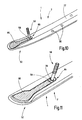
- FIG. 1 shows a roof rack system 1 with a roof strip 2.
- the roof strip four studs 50 are arranged, wherein the studs 50 are screwed to the front end 52 of the roof rail 2 and the rear end 54 of the roof rail 2 in sliding blocks, while the other two studs screwed into blind rivets are.
- On the vehicle body 13 are corresponding holes 55 in which the stud bolts 50 are inserted and then attached from the inside of the body ago.
- the attachment from the inside is preferably made by means of nuts, which cooperate with a thread formed on the stud.
- the roof bar 2 at its front and rear ends 52, 54 is flattened.
- a roof carrier mounting edge 56 can be seen, in which a claw of a roof rack mounting can engage.
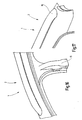
- FIG. 2 shows a roof rail 2, which is arranged on a vehicle body 13. It is to recognize the nut 58, which is arranged in a cavity 60 of the roof rail 2. In the nut 60, a stud bolt 62 is screwed, which projects through a recess 64 in the roof rail 2 passes. On a second thread 68, a nut 70 is arranged, which ensures the attachment of the roof rail 2 of a vehicle body 13 in conjunction with the washer 72. To ensure that when mounting the roof rail 2, the space between an upper plate 76 and a lower plate 78 is not compressed formed.
- the function of this spacer system 74 is from the German utility model number 202 05 087.4 , registered on June 13, 2002, known. The explanations there to the spacer system 74 are hereby expressly incorporated into this application.
- FIG. 3 shows a roof rail 2 in the view of the contact surface 27 ago. It can be clearly seen that the recess 64 is widened at the front end 52 of the roof rail 2. As a result, the insertion of the sliding block 58 is facilitated. With a dashed line of the nut 58 is shown in a position in which just in the enlarged area of the recess 64 has been inserted into the roof rail 2.
- FIG. 4 shows a recess 64 which is not arranged at one end of the roof rail 2. Again, there is an enlarged area through which the nut 58 can be inserted into the cavity of the roof rail 2. By a shift in the direction of the longitudinal direction L of the roof rail 2 of the sliding block in a narrowed region of the recess 64 is displaced, so that the sliding block 58 can not escape from the cavity 60 again.
- FIG. 5 shows a stud bolt 50 having a first thread 66, a second thread 68 and a retaining edge 70.
- the first thread 66 engages in a thread of a sliding block 60, while the thread 68 is used to attach the roof rail 2 from the vehicle interior.
- FIG. 6 shows a sliding block 58, with a continuous thread 80.
- the cross section of the sliding block 58 is adapted to the inner profile of the roof rail 2.
- the sliding block 58 also has a projection 82, with which the sliding block 58 is guided within the recess 64.
- FIG. 7 shows a nut 58 from the bottom. In this case, clearly two grooves 84 can be seen, which cause a guide of the sliding block 58 within the recess 64.
- FIG. 8 shows a sliding block 58 with screwed stud 50. By the edge 70 results in a well-defined seat of the stud 50th
- FIG. 9 shows the nut 58 with threaded stud bolts 50 in a three-dimensional view. It can be seen here that the projection 82 has a rounding. This rounding allows a fitting abutment against the end of the recess 64 against which the sliding block 58 abuts when it is positioned. A rounded end of the recess 64 is advantageous in terms of manufacture and stability.
- FIG. 10 shows a portion of a roof rail 2 when viewed from the side of the contact surface 27, so from the bottom.
- a stud 50 is screwed in the nut 58.
- the sliding block is longitudinally on the one hand from the recess end 86 and on the other fixed by the plastic locking element 88.
- the two blind holes 90 allow the fixation of a cross member.
- FIG. 11 shows the front portion 52 of a roof strip 2 and illustrates the insertion of the plastic locking element 88th
- FIG. 12 shows the front portion 52 of a roof strip 2 in the side view. Here, the roof rack mounting edge 56 is clearly visible.
- FIG. 13 shows a arranged in a blind rivet 92 stud 50.
- side elevations 90 are executed, which among other things clearly define the system of the roof rail 2 on the vehicle body 13 or the positioning of a foam seal below the roof rail 2 can serve.
- FIG. 14 shows a plastic locking element 88 with guide wings 94.
- the plastic locking element 88 is shaped so that it forms with its bottom 96 a roughly plan conclusion to the contact surface 27 and that it follows with its top 98 of the shape of the roof rail 2.
- FIG. 15 shows a further embodiment.
- the contact surface 27 is formed on two wide support webs 25 and rests on a seal 100.
- the roof surface is symbolized by the dashed line 102.
- the seal 100 rests on an adhesive strip 104.
- the sliding block 58 has a thread 106 and is inserted into a hollow space 60 of the roof rail 2.
- a roof rack system 1 according to the invention but can also be dispensed with a seal 100, since there are only very small gaps.
- the starting material for the production of a roof strip is shaped according to delivery by mechanical or by means of liquid or gase-druckbeauf flowdem method of the vehicle contour, so that a low-gap overhead roof rack or roof rail system arises.
- the seam is then preferably welded.
- the ends of the roof strip are now processed over a, usually cutting process, for the introduction of recordings.
- a milling in a milling direction in the longitudinal direction of the roof strip is advantageous.
- the processing is necessary to mounting material, so the introduced sliding block and the screwed studs to install, since the railing, because of the overlying characteristics of the vehicle interior can be mounted very easy.
- Semi-fabricating processes can therefore be used which represents an overall reduction in price compared to the techniques used hitherto.
- This sliding block preferably made of investment casting, especially GS 38, brings a high tensile strength.
- the sliding block is preferably held in position by a plastic injection molded part.
- stud bolts are introduced at regular intervals by, introduced in a simple bore blind rivet nut. These set the connection to load-bearing parts the body. Since the main weight rests on the two sliding blocks, it is therefore possible to work here by means of a sufficiently dimensioned blind nut.
- a foam gasket for example type EPDM, is mounted on the underside of the roof strip.
Abstract
Description
Die Erfindung betrifft ein Dachträgersystem für ein Fahrzeug, insbesondere für einen Personenkraftwagen, sowie ein enstprechendes Verfahren zur Herstellung des Dachträgersystems und Fahrzeug mit einem Dachträgersystem.The invention relates to a roof rack system for a vehicle, in particular for a passenger car, as well as a corresponding method for producing the roof rack system and vehicle with a roof rack system.
Personenkraftwagen können auf ihrem Dach ein Dachträgersystem in Form einer Dachreling, die aus zwei, parallel zueinander angeordneten Dachleisten bestehen, besitzen. Diese Dachleisten können ein- oder mehrteilig gestaltet sein. Dachleisten, welche drei- oder mehrteilig gestaltet sind, weisen mindestens ein Mittelteil sowie zwei mit dem Mittelteil zusammengesteckte Endteile auf. Die beiden Endteile sind mit einem Abstand zur Dachfläche des Fahrzeugs erzeugenden Fußstreben versehen. Eine entsprechende Fußstrebe ist im mittleren Bereich des Mittelteils angeordnet. Die bekannte Dachreling hat sich bewährt und gibt dem Fahrzeug ein charakteristisches Aussehen.Passenger cars can on their roof, a roof rack system in the form of a roof rail, which consist of two, mutually parallel roof strips, own. These roof strips can be designed in one or more parts. Roof strips, which are designed in three or more parts, have at least one central part and two end pieces joined together with the middle part. The two end parts are provided with a distance to the roof surface of the vehicle generating foot struts. A corresponding Fußstrebe is arranged in the central region of the middle part. The well-known roof rail has proven itself and gives the vehicle a characteristic appearance.
Die Erfindung befasst sich mit einer neuartigen und kostengünstigen Konstruktion eines Dachträgersystems mit dem ein besonderer, optischer Effekt einhergeht.The invention is concerned with a novel and inexpensive construction of a roof rack system with which a special, optical effect is associated.
Druckschrift
Für das erfindungsgemäße Dachträgersystem ist mindestens eine Dachleiste vorgesehen, die eine im Wesentlichen durchgängig auf die Fahrzeugkarosserie auflegbare, sich über die Länge der Dachleiste erstreckende, der Fahrzeugkarosserie angepasste Auflagefläche aufweist. Durch die fußstrebenfreie Konstruktion überragt die Dachleiste das Fahrzeugdach nur etwa in Höhe der Leistendicke bei hochgenauem Passsitz zur Fahrzeugkarosseriekontur, insbesondere zu den Seitenwandrahmen des Kraftfahrzeugs, auf denen die Dachleisten montierbar sind. Die Anlagefläche entspricht im Wesentlichen der Fahrzeugkarosseriekontur. Es kann dabei auf Abdeckmittel, wie zum Beispiel Einfassgummis oder dergleichen verzichtet werden. Es ist es möglich, direkt auf dem Fahrzeugdach und dieses nur wenig überragende Dachleisten anzuordnen, die ferner zu ebenmäßigen und daher optisch sehr ansprechenden Randspalten führt. Die Konturierung der Dachleiste wird durch einen formgebenden Biegevorgang erzeugt. Es ist eine Befestigungsvorrichtung zur Befestigung der Dachleiste an der Fahrzeugkarosserie vorgesehen. Die Befestigungsvorrichtung weist ein Halteelement auf, dass in einem Hohlraum der Dachleiste nach Art eines Nutsteins angeordnet ist. Hierdurch lässt sich die Dachleiste nach außen unsichtbar am Fahrzeugdach festlegen. Die Befestigung kann sehr hohe Lasten bewältigen und ist selbst in den abgeflachten Endbereichen der Dachleiste problemlos einsetzbar.At least one roof strip is provided for the roof carrier system according to the invention, which has a contact surface which can be laid on the vehicle body essentially continuously and extends over the length of the roof strip, adapted to the vehicle body. Due to the Fußstrebenfreie construction, the roof bar dominates the vehicle roof only about the height of the bar with highly accurate fit to the vehicle body contour, in particular to the side wall frame of the vehicle on which the roof rails are mounted. The contact surface essentially corresponds to the vehicle body contour. It can be dispensed with covering means, such as Fassbummis or the like. It is possible to arrange directly on the vehicle roof and this little towering roof battens, which also leads to even and therefore visually very appealing edge columns. The contouring of the roof strip is produced by a shaping bending process. There is provided a fastening device for fastening the roof strip to the vehicle body. The fastening device has a holding element that is arranged in a cavity of the roof strip in the manner of a sliding block. This makes it possible to set the roof bar invisible to the outside on the vehicle roof. The attachment can handle very high loads and is easily used even in the flattened end portions of the roof rail.
Die Dachleiste weist mindestens eine Ausnehmung auf, die an ihrer dem Fahrzeugdach zugewandten Seite angeordnet ist. Die Ausnehmung erstreckt sich dabei ausgehend von den Enden der Dachleiste in Längsrichtung der Dachleiste. Die Breite der Ausnehmung ist dabei geringer, insbesondere deutlich geringer, als die Breite der Anlagefläche. Die Dachleiste weist einen zumindest teilweise umschlossenen Hohlraum auf. Durch die Ausnehmung ergibt sich eine bereichsweise Öffnung des Hohlraums (Hohlprofils). Durch diese Öffnung des Hohlraums wird ein Halteelement, insbesondere ein Nutenstein, in den Hohlraum eingeschoben. Der Nutenstein ist insbesondere ein Gussteil. An dem Haltelement ist ein Befestigungselement angeordnet, insbesondere ein Stehbolzen mit einem Gewinde, den in ein im Nutenstein angeordnetes Gewinde eingreift. Das Gewinde ist am Nutenstein derart angeordnet, dass auch im eingeschobenen Zustand des Nutensteins die Gewindeöffnung durch die Ausnehmung hindurch erreichbar ist. Dadurch wird es in einem nächsten Schritt möglich einen Stehbolzen, der zumindest teilweise mit einem Gewinde versehen ist, in das Gewinde des Nutensteins einzudrehen. Zwar ist es grundsätzlich auch möglich, Nutenstein und Stehbolzen einstückig zu fertigen, doch ergibt sich durch die zweiteilige Herstellung eine Vereinfachung des Produktionsprozesses. Die Gewinde am Stehbolzen sind dabei derart angeordnet, dass das Gewinde am einen Ende des Stehbolzens in das Gewinde des Nutensteins eingreift und dass ein zweites Gewinde am Stehbolzen die sichere Befestigung des Stehbolzens an der Fahrzeugkarosserie mittels einer Schraubverbindung ermöglicht. An den Enden der Dachleiste kann die Ausnehmung vergrößert sein, um das Einführen des Nutensteins zu erleichtern. Dies ist insbesondere dann hilfreich, wenn die Dachleiste an Ihren Enden flach zuläuft. In einem optionalen Schritt kann nun zusätzlich ein Plastiksperrelement in den Hohlraum nachgeschoben werden, so dass der Nutenstein zwischen dem Ende der Ausnehmung und dem Plastiksperrelement festgehalten wird. Dies vereinfacht die Montage, da der Nutenstein so fixiert ist.The roof strip has at least one recess which is arranged on its side facing the vehicle roof. The recess extends starting from the ends of the roof strip in the longitudinal direction of the roof strip. The width of the recess is smaller, in particular significantly smaller than the width of the contact surface. The roof rail has an at least partially enclosed cavity. The recess results in a partial opening of the cavity (hollow profile). Through this opening of the cavity, a holding element, in particular a sliding block, is inserted into the cavity. The nut is in particular a casting. On the holding element, a fastening element is arranged, in particular a stud with a thread which engages in a thread arranged in the sliding block. The thread is arranged on the sliding block in such a way that, even in the inserted state of the sliding block, the threaded opening can be reached through the recess. This makes it possible in a next step, a stud, which is at least partially provided with a thread to screw into the thread of the sliding block. Although it is in principle also possible to manufacture sliding block and stud bolts in one piece, the two-part production results in a simplification of the production process. The threads on the stud are arranged such that the thread at one end of the stud engages in the thread of the sliding block and that a second thread on the stud allows secure attachment of the stud to the vehicle body by means of a screw connection. At the ends of the roof rail, the recess may be enlarged in order to facilitate the insertion of the sliding block. This is especially useful when the roof rail tapers at the ends. In an optional step, a plastic locking element can now additionally be pushed into the cavity, so that the sliding block is held between the end of the recess and the plastic locking element. This simplifies assembly, since the nut is fixed so.
Die Dachleiste weist in ihrem Querschnitt ein Profil auf. Dabei ist der Querschnitt des Nutensteins vorzugsweise dem inneren Querschnitt der Dachleiste angepasst. Dadurch können auch große Kräfte, die zwischen der Fahrzeugkarosserie und dem Dachträgersystem wirken sicher aufgenommen werden. Der Nutenstein weist vorzugsweise an seiner der Ausnehmung zugewandten Seite einen Vorsprung auf, der in die Ausnehmung eingreift und so eine Führung des Nutensteins und einen Anschlag des Nutensteins innerhalb der Ausnehmung ermöglicht.The roof strip has a profile in its cross section. In this case, the cross section of the sliding block is preferably adapted to the inner cross section of the roof strip. As a result, even large forces acting between the vehicle body and the roof rack system can be safely absorbed. The sliding block preferably has on its side facing the recess on a projection which engages in the recess and thus allows a guide of the sliding block and a stop of the sliding block within the recess.
Mittels der Erfindung ist es also insbesondere möglich eine einstückige Dachleiste zu fertigen, da die tragende Befestigung der Dachleiste nun mittels mindestens eines Haltelementes erfolgt, das über mindestens ein Befestigungselement mit der Fahrzeugkarosserie verbunden wird. Es lassen sich daher zusätzliche teure Füße zur Befestigung der Dachleiste vermeiden. Zudem lässt sich so eine nahezu spaltfreie Anordnung der Dachleiste an der Fahrzeugkarosserie realisieren.By means of the invention, it is thus possible in particular to manufacture a one-piece roof strip, since the supporting attachment of the roof strip is now effected by means of at least one retaining element, which is connected via at least one fastening element to the vehicle body. It can therefore avoid additional expensive feet for attaching the roof strip. In addition, a nearly gap-free arrangement of the roof strip on the vehicle body can be realized in this way.
Die Ausnehmung kann auch von den Enden der Dachleiste entfernt angeordnet sein, doch ergibt sich mittels der vorgeschlagenen Anordnung eine besonders günstige Anordnung der tragenden Halte-und Befestigungselemente, sowie eine hohe Stabilität der Dachleiste.The recess can also be arranged away from the ends of the roof strip, but results by means of the proposed arrangement, a particularly favorable arrangement of the supporting holding and fastening elements, and a high stability of the roof strip.
Die Erfindung wird nun anhand von Ausführungsbeispielen näher erläutert. Dabei zeigen
Figur 1- die Anordnung einer Dachleiste auf einer Fahrzeug- karosserie,
Figur 2- die Befestigung der Dachleiste an der Fahrzeugkaros- serie mittels eines Nutensteins und Stehbolzens,
- Figur 3
- eine Ausnehmung an einem Ende der Dachleiste,
- Figur 4
- eine Ausnehmung in der Dachleiste, die vom Ende der Dachleiste abgesetzt ist,
- Figur 5
- einen Stehbolzen mit zwei Gewinden,
- Figur 6
- einen Nutenstein in einer Ansicht von oben,
- Figur 7
- einen Nutenstein in der Ansicht von unten,
- Figur 8
- einen Nutenstein mit eingeschraubten Stehbolzen in der Draufsicht,
- Figur 9
- einen Nutenstein mit eingeschraubten Stehbolzen in einer dreidimensionalen Ansicht,
- Figur 10
- einen Ausschnitt aus einer Dachleiste,
- Figur 11
- ein Ende einer Dachleiste in einer dreidimensionalen Ansicht,
- Figur 12
- das Ende einer Dachleiste in einer Seitenansicht,
Figur 13- einen Stehbolzen in einer in der Dachleiste angeordne- ten Blindniete,
- Figur 14
- ein Plastiksperrelement, und
- Figur 15
- einen Querschnitt durch eine Dachleiste mit eingeführ- tem Nutenstein,
- Figur 16
- das vordere Ende der Dachleiste, und
- Figur 17
- das hintere Ende der Dachleiste.
- FIG. 1
- the arrangement of a roof rail on a vehicle body,
- FIG. 2
- the attachment of the roof rail to the vehicle body by means of a sliding block and stud bolt,
- FIG. 3
- a recess at one end of the roof rail,
- FIG. 4
- a recess in the roof rail, which is offset from the end of the roof rail,
- FIG. 5
- a stud with two threads,
- FIG. 6
- a sliding block in a view from above,
- FIG. 7
- a sliding block in the view from below,
- FIG. 8
- a sliding block with screwed studs in plan view,
- FIG. 9
- a sliding block with screwed studs in a three-dimensional view,
- FIG. 10
- a section of a roof strip,
- FIG. 11
- one end of a roof rail in a three-dimensional view,
- FIG. 12
- the end of a roof rail in a side view,
- FIG. 13
- a stay bolt in a blind rivet arranged in the roof rail,
- FIG. 14
- a plastic locking element, and
- FIG. 15
- a cross section through a roof strip with inserted sliding block,
- FIG. 16
- the front end of the roof rail, and
- FIG. 17
- the rear end of the roof rail.
Nachfolgend wird nun das Herstellungsverfahren näher erläutert.The production process will now be explained in more detail.
Das Vormaterial zur Herstellung einer Dachleiste, wird nach Anlieferung durch mechanische beziehungsweise mittels flüssigkeits- oder gasförmig-druckbeaufschlagendem Verfahren der Fahrzeugkontur entsprechend geformt, so dass ein spaltarmes aufliegendes Dachträger- beziehungsweise Dachleisten-System entsteht.The starting material for the production of a roof strip is shaped according to delivery by mechanical or by means of liquid or gase-druckbeaufschlagendem method of the vehicle contour, so that a low-gap overhead roof rack or roof rail system arises.
Es kann als Grundkörper dabei insbesondere ein Strangpressprofilrohr, ein gewalztes Profilrohr oder auch ein gestanztes Profilrohr verwendet werden. Bei den letzten beiden Herstellungsverfahren wird die Naht anschließend vorzugsweise verschweißt.It can be used as a body in particular an extruded profile tube, a rolled profile tube or a stamped profile tube. In the last two manufacturing processes, the seam is then preferably welded.
Daran anschließend werden die Enden der Dachleiste nunmehr über ein, in der Regel spanendes Verfahren, zur Einbringung von Aufnahmen bearbeitet. Dabei ist insbesondere ein Fräsen in einer Fräsrichtung in Längsrichtung der Dachleiste vorteilhaft.Subsequently, the ends of the roof strip are now processed over a, usually cutting process, for the introduction of recordings. In particular, a milling in a milling direction in the longitudinal direction of the roof strip is advantageous.
Die Bearbeitung wird notwendig um Montagematerial, also den eingebrachten Nutenstein und den eingeschraubten Stehbolzen, anzubringen, da die Reling, wegen der aufliegenden Charakteristik von der Fahrzeuginnenseite her besonders einfach montiert werden kann.The processing is necessary to mounting material, so the introduced sliding block and the screwed studs to install, since the railing, because of the overlying characteristics of the vehicle interior can be mounted very easy.
Es können also halbzeugherstellende Verfahren eingesetzt werden, die eine Gesamtpreisreduzierung zu den bisherigen verwendeten Techniken darstellt.Semi-fabricating processes can therefore be used which represents an overall reduction in price compared to the techniques used hitherto.
Die Enden erhalten somit eine zugänglichen Hohlraum, gewissermaßen eine Tasche, für einen Nutenstein mit Gewinde. Dieser Nutenstein, vorzugsweise aus Feinguss, insbesondere GS 38, bringt eine hohe Zugausreißfestigkeit. Der Nutenstein wird vorzugsweise durch ein Kunststoffspritzgussteil in Position gehalten. Um die geforderten Nutzlasten von Dachleisten-Relingsystems auf das Fahrzeugdach übertragen zu können, werden in regelmäßigen Abständen durch, in einer einfachen Bohrung eingebrachten Blindnietmutter Stehbolzen eingebracht. Diese stellen die Verbindung zu tragenden Teilen an der Karosserie her. Da das Hauptgewicht auf den beiden Nutensteinen ruht, kann daher hier mittels einer ausreichend dimensionierten Blindmutter gearbeitet werden.The ends thus receive an accessible cavity, effectively a pocket, for a threaded nut. This sliding block, preferably made of investment casting, especially GS 38, brings a high tensile strength. The sliding block is preferably held in position by a plastic injection molded part. In order to transfer the required payloads of roof railing rail system on the vehicle roof, stud bolts are introduced at regular intervals by, introduced in a simple bore blind rivet nut. These set the connection to load-bearing parts the body. Since the main weight rests on the two sliding blocks, it is therefore possible to work here by means of a sufficiently dimensioned blind nut.
Um Kratzbeschädigungen am lackierten Fahrzeug zu vermeiden wird eine Schaumstoffdichtung zum Beispiel Typ EPDM auf der Unterseite der Dachleiste angebracht.In order to avoid scratch damage to the painted vehicle, a foam gasket, for example type EPDM, is mounted on the underside of the roof strip.
Claims (22)
- Roof rack system (1) for a vehicle, in particular for a passenger car, having at least one roof rail (2) which is configured in one piece and can be located with an attaching device to the vehicle body (13), wherein the roof rail (2) has a contact surface (27) extending over the length of the roof rail (2), the contact surface (27) being placeable substantially continuously on the vehicle body (13) and is conformed to the vehicle body contour, and the attaching device has a retaining element (58) which is located in a cavity (60) of the roof rail (2) in the manner of a slot nut, characterized in that the roof rail (2) has at least one recess (64) in the contact surface (27) to create an access to the cavity (60), that the recess (64) has an enlarged area to insert the retaining element (58) which forms a slot nut and further that a narrowed area is provided into which the slot nut is displaced such that it cannot exit from the cavity (60).
- Roof rack system according to claim 1, characterized in that the roof rail (2) has a hollow profile with the cavity (60).
- Roof rack system according to one of the preceding claims, characterized in that the roof rail (2) has at least one recess (64) in the contact surface (27) to create an access to the cavity (60).
- Roof rack system according to one of the preceding claims, characterized in that an attaching element (50) is arranged in the retaining element (58) to attach the roof rail (2) to the vehicle body (13).
- Roof rack system according to claim 4, characterized in that the attaching element (50) is a stud bolt.
- Roof rack system according to one of the claims 4 or 5, characterized in that the attaching element (50) is screwed into the retaining element (58).
- Roof rack system according to one of the claims 5 or 6, characterized in that the stud bolt has a first thread (66), a second thread (68) and a retaining lip (70) lying between the threads (66, 68), wherein the first thread (66) is screwed into a thread of the retaining element (58).
- Roof rack system according to one of the preceding claims, characterized in that the cross-section of the retaining element (58) is matched to the inside profile of the roof rail (2).
- Roof rack system according to one of the claims 3 to 8, characterized in that the retaining element (58) has a projection (82) acting to guide it in the recess (64).
- Roof rack system according to claim 9, characterized in that the projection (82) has a curvature which abuts the end of the recess (64) in matching contact.
- Roof rack system according to one of the preceding claims, characterized in that the retaining element (58) is locked in position in the cavity (60) by means of a plastic locking element (88).
- Roof rack system according to one of the preceding claims, characterized in that the contact surface (27) is a contact surface conformed by post-machining.
- Roof rack system according to one of the preceding claims, characterized in that the contact surface (27) is configured and arranged in such a way that at least the outer lateral edge (30) of the roof rail (2) assigned to the vehicle body (13) forms a shadow joint (31) with the vehicle body (13).
- Roof rack system according to one of the preceding claims, characterized in that the contact surface (27) is formed on at least one base web (25).
- Roof rack system according to one of the preceding claims, characterized in that the roof rail (2) consists of aluminum, magnesium, steel and/or brass, or their alloys respectively.
- Roof rack system according to claim 15, characterized in that the surface of the aluminum roof rail (2) is polished and anodized or paint coated respectively.
- Roof rack system according to one of the preceding claims, characterized in that the surface of the roof rail (2) is provided with a surface coating.
- Roof rack system according to claim 17, characterized in that the surface coating is chrome plating, a powder and/or paint coating.
- Method for producing a roof rack system according to one or more of the preceding claims, characterized in that, with the roof rail formed in one piece, it is bent to correspond to the vehicle body contour and by means of a material-removing step at least one recess is created in the longitudinal direction of the roof rail, in particular at the ends of the roof rail.
- Method according to claim 19, characterized in that following the machining the aluminum roof rail is polished and anodized, or paint coated respectively.
- Vehicle with at least one roof rail according to one or more of the preceding claims, characterized in that the vehicle body, in particular each side panel frame of the vehicle, has at least one gutter-shaped depression which partially accommodates a roof rail in the area of its contact surface.
- Vehicle according to claim 21, having two roof rails arranged in parallel on the vehicle body, in particular on the two side panel frames of the vehicle, according to one or more of the preceding claims.
Priority Applications (2)
| Application Number | Priority Date | Filing Date | Title |
|---|---|---|---|
| SI200531019T SI1794031T1 (en) | 2004-09-24 | 2005-09-21 | Roof rack system for a vehicle, method for producing the roof rack system and vehicle comprising a roof rack system |
| PL05796825T PL1794031T3 (en) | 2004-09-24 | 2005-09-21 | Roof rack system for a vehicle, method for producing the roof rack system and vehicle comprising a roof rack system |
Applications Claiming Priority (3)
| Application Number | Priority Date | Filing Date | Title |
|---|---|---|---|
| DE102004047565 | 2004-09-24 | ||
| DE102005018158A DE102005018158A1 (en) | 2004-09-24 | 2005-04-20 | Roof rack system for a vehicle and method of making the roof rack system and vehicle having a roof rack system |
| PCT/EP2005/010198 WO2006032474A2 (en) | 2004-09-24 | 2005-09-21 | Roof rack system for a vehicle, method for producing the roof rack system and vehicle comprising a roof rack system |
Publications (2)
| Publication Number | Publication Date |
|---|---|
| EP1794031A2 EP1794031A2 (en) | 2007-06-13 |
| EP1794031B1 true EP1794031B1 (en) | 2010-03-24 |
Family
ID=35524283
Family Applications (1)
| Application Number | Title | Priority Date | Filing Date |
|---|---|---|---|
| EP05796825A Not-in-force EP1794031B1 (en) | 2004-09-24 | 2005-09-21 | Roof rack system for a vehicle, method for producing the roof rack system and vehicle comprising a roof rack system |
Country Status (12)
| Country | Link |
|---|---|
| US (1) | US7980437B2 (en) |
| EP (1) | EP1794031B1 (en) |
| AT (1) | ATE461844T1 (en) |
| BR (2) | BRPI0516036A (en) |
| CA (1) | CA2581404C (en) |
| DE (2) | DE102005018158A1 (en) |
| ES (1) | ES2340406T3 (en) |
| MX (1) | MX2007003494A (en) |
| PL (1) | PL1794031T3 (en) |
| PT (1) | PT1794031E (en) |
| SI (1) | SI1794031T1 (en) |
| WO (1) | WO2006032474A2 (en) |
Cited By (1)
| Publication number | Priority date | Publication date | Assignee | Title |
|---|---|---|---|---|
| EP2543548A1 (en) | 2011-07-06 | 2013-01-09 | DURA Automotive Body & Glass Systems GmbH | Fixing system for a motor vehicle roof rack |
Families Citing this family (24)
| Publication number | Priority date | Publication date | Assignee | Title |
|---|---|---|---|---|
| DE102005017884A1 (en) * | 2005-04-19 | 2006-10-26 | Hans und Ottmar Binder GmbH Oberflächenveredelung | Roof rack for a vehicle and method for securing the roof rack |
| DE102006005541A1 (en) * | 2006-02-07 | 2007-08-16 | Hans und Ottmar Binder GmbH Oberflächenveredelung | Process for the surface treatment of roof racks for motor vehicles and roof racks for motor vehicles |
| DE102007019617B4 (en) | 2007-04-24 | 2009-08-13 | Jac Products Deutschland Gmbh | Roof rack system |
| DE102009023950A1 (en) * | 2009-06-04 | 2010-12-09 | Mayer Gmbh | Device for connecting roof luggage rack to surface of motor vehicle, has fixing element formed from plastic and provided with insert that is formed from metal, metal alloy or ceramics and provided with opening |
| CZ303740B6 (en) * | 2011-03-09 | 2013-04-17 | Acl Automotive S.R.O. | Vehicle roof rack |
| CZ303845B6 (en) * | 2011-10-12 | 2013-05-22 | Acl Technology S.R.O. | Field joint of longitudinal roof carrier to vehicle roof, removable fixed field joint of two parts, nut with spherical contact surface for the field joint and process for producing such nut |
| DE102011054861A1 (en) | 2011-10-27 | 2013-05-02 | Böllhoff Verbindungstechnik GmbH | Fastening element with tolerance compensation function |
| DE102013003133A1 (en) | 2013-02-26 | 2014-09-11 | Hans und Ottmar Binder GmbH Oberflächenveredelung | Roof rail holder and roof rail assembly and vehicle with the roof rail assembly |
| US9133870B2 (en) | 2013-04-03 | 2015-09-15 | Ford Global Technologies, Llc | Adjustable tower stud assembly |
| EP2871097B1 (en) * | 2013-11-07 | 2018-12-26 | Thule Sweden AB | A load carrier foot |
| DE102014104920B4 (en) * | 2013-11-19 | 2022-10-06 | Dr. Ing. H.C. F. Porsche Aktiengesellschaft | Body structure with roof rails |
| DE102014203558A1 (en) * | 2014-02-27 | 2015-08-27 | Bayerische Motoren Werke Aktiengesellschaft | Fastening arrangement for a roof attachment of a motor vehicle |
| CN104925000B (en) | 2014-03-19 | 2017-05-17 | 通用汽车环球科技运作有限责任公司 | Assembly provided with sliding joint and used for fastening vehicle components and assembling method |
| DE202015004902U1 (en) * | 2015-07-08 | 2016-10-13 | GM Global Technology Operations LLC (n. d. Ges. d. Staates Delaware) | Roof rail for releasable attachment to the roof frame of a motor vehicle |
| US10005403B2 (en) | 2015-10-30 | 2018-06-26 | Teraflex, Inc. | Roof rack system |
| CN107081590B (en) * | 2017-04-24 | 2023-06-27 | 敏实汽车技术研发有限公司 | Automatic assembly tool for three-section type longitudinal beam of luggage rack aluminum pipe |
| CN107284362B (en) * | 2017-06-15 | 2023-06-20 | 宁波信泰机械有限公司 | Fixing mechanism for preventing plastic luggage rack from expanding with heat and contracting with cold |
| CN107838634A (en) * | 2017-09-14 | 2018-03-27 | 明达铝业科技(太仓)有限公司 | A kind of loss of weight high intensity top holder structure and its processing method |
| KR102429070B1 (en) * | 2017-12-13 | 2022-08-05 | 현대자동차주식회사 | Apparatus for mounting roof rack of vehicle |
| DE102018122701A1 (en) * | 2018-09-17 | 2020-03-19 | Frauenthal Automotive Service Gmbh | Holder system for attaching a container to a vehicle |
| CN109334583A (en) * | 2018-10-16 | 2019-02-15 | 宁波信泰机械有限公司 | A kind of automobile luggage racks tolerance regulating device |
| KR102085081B1 (en) * | 2018-10-19 | 2020-03-06 | 에코플라스틱 주식회사 | Vehicle roof rack mounting structure |
| CN111016806A (en) * | 2019-12-30 | 2020-04-17 | 宁波吉利汽车研究开发有限公司 | Structure for installing luggage rack for vehicle |
| US11912240B2 (en) * | 2021-11-04 | 2024-02-27 | Jac Products, Inc. | Vehicle article carrier rack system with stowable, concealable cross bars |
Family Cites Families (13)
| Publication number | Priority date | Publication date | Assignee | Title |
|---|---|---|---|---|
| DE8621340U1 (en) * | 1986-08-08 | 1989-07-06 | Daimler-Benz Aktiengesellschaft, 7000 Stuttgart, De | |
| DE3626926A1 (en) | 1986-08-08 | 1988-02-18 | Daimler Benz Ag | Fastening for attaching covering strips to motor vehicle roofs |
| US4911349A (en) * | 1989-07-03 | 1990-03-27 | Starboard Industries, Inc. | End cap with captive stud for article carriers |
| DE8910936U1 (en) * | 1989-09-13 | 1990-10-11 | Hymer-Leichtmetallbau, 7988 Wangen, De | |
| US5312005A (en) * | 1991-07-25 | 1994-05-17 | Odell Gordon T | Rack release mounting assembly |
| DE9414529U1 (en) | 1994-09-08 | 1994-12-22 | Schmalzhofer Rainer | Sliding block for a profile bar |
| JP3580508B2 (en) * | 1995-07-20 | 2004-10-27 | 富士重工業株式会社 | Vehicle roof rails |
| DE19649758A1 (en) | 1996-11-30 | 1998-06-04 | Oris Fahrzeugteile Riehle H | Roof rail system for motor vehicles |
| DE19912078C2 (en) | 1999-03-18 | 2001-03-22 | Jac Products Deutschland Gmbh | Roof rails for vehicles |
| DE19948476C1 (en) * | 1999-10-08 | 2001-03-01 | Jac Products Deutschland Gmbh | Automobile roof rail has gallery rail provided at either end with plug-in rail foot provided by high pressure deformation of tubular section of same metallic material as gallery rail |
| DE20205087U1 (en) * | 2002-03-25 | 2002-06-13 | Sueddeutsche Aluminium Manufak | Roof rack system for a motor vehicle |
| DE10221943A1 (en) | 2002-05-17 | 2003-11-27 | Sueddeutsche Aluminium Manufak | Roof rack system for a vehicle and method for manufacturing the roof rack system and vehicle with a roof rack system |
| DE10354117B4 (en) * | 2003-11-19 | 2007-08-23 | Süddeutsche Aluminium Manufaktur GmbH | Tolerance compensation element |
-
2005
- 2005-04-20 DE DE102005018158A patent/DE102005018158A1/en not_active Withdrawn
- 2005-09-21 PL PL05796825T patent/PL1794031T3/en unknown
- 2005-09-21 BR BRPI0516036-7A patent/BRPI0516036A/en active IP Right Grant
- 2005-09-21 US US11/663,665 patent/US7980437B2/en active Active
- 2005-09-21 EP EP05796825A patent/EP1794031B1/en not_active Not-in-force
- 2005-09-21 CA CA2581404A patent/CA2581404C/en not_active Expired - Fee Related
- 2005-09-21 AT AT05796825T patent/ATE461844T1/en active
- 2005-09-21 PT PT05796825T patent/PT1794031E/en unknown
- 2005-09-21 MX MX2007003494A patent/MX2007003494A/en active IP Right Grant
- 2005-09-21 BR BRMU8503593-9U patent/BRMU8503593Y1/en not_active IP Right Cessation
- 2005-09-21 DE DE502005009280T patent/DE502005009280D1/en active Active
- 2005-09-21 ES ES05796825T patent/ES2340406T3/en active Active
- 2005-09-21 SI SI200531019T patent/SI1794031T1/en unknown
- 2005-09-21 WO PCT/EP2005/010198 patent/WO2006032474A2/en active Application Filing
Cited By (2)
| Publication number | Priority date | Publication date | Assignee | Title |
|---|---|---|---|---|
| EP2543548A1 (en) | 2011-07-06 | 2013-01-09 | DURA Automotive Body & Glass Systems GmbH | Fixing system for a motor vehicle roof rack |
| DE102011051613A1 (en) | 2011-07-06 | 2013-01-10 | Dura Automotive Body & Glass Systems Gmbh | Mounting system for a motor vehicle roof rack |
Also Published As
| Publication number | Publication date |
|---|---|
| ES2340406T3 (en) | 2010-06-02 |
| WO2006032474A8 (en) | 2006-07-27 |
| US20080099519A1 (en) | 2008-05-01 |
| BRMU8503593Y1 (en) | 2017-11-21 |
| MX2007003494A (en) | 2007-10-10 |
| CA2581404A1 (en) | 2006-03-30 |
| WO2006032474A3 (en) | 2006-06-15 |
| US7980437B2 (en) | 2011-07-19 |
| CA2581404C (en) | 2013-01-22 |
| PL1794031T3 (en) | 2010-08-31 |
| WO2006032474A2 (en) | 2006-03-30 |
| DE102005018158A1 (en) | 2006-04-06 |
| DE502005009280D1 (en) | 2010-05-06 |
| BRPI0516036A (en) | 2008-03-04 |
| SI1794031T1 (en) | 2010-07-30 |
| PT1794031E (en) | 2010-05-17 |
| ATE461844T1 (en) | 2010-04-15 |
| EP1794031A2 (en) | 2007-06-13 |
Similar Documents
| Publication | Publication Date | Title |
|---|---|---|
| EP1794031B1 (en) | Roof rack system for a vehicle, method for producing the roof rack system and vehicle comprising a roof rack system | |
| EP2804786B1 (en) | Roof rail for a vehilce | |
| DE102006012050B4 (en) | Roof rail for a motor vehicle and method for producing a roof rail | |
| DE19946804A1 (en) | Vehicle roof module with integrated sunroof unit | |
| DE102012212305B4 (en) | Loading floor and method for producing a loading floor | |
| EP0580023B1 (en) | Roof rails for vehicles | |
| DE102006014719B4 (en) | Carrier profile and mounting arrangement of a seat underframe on a ground system of a bus | |
| EP0723506B1 (en) | Rails for car roofs | |
| DE3409582A1 (en) | DEVICE FOR ADJUSTING THE SEAT | |
| EP0645282A1 (en) | Stanchion for supporting the end of a vehicle roof rack rail | |
| DE4014385A1 (en) | Motor vehicle body work - has support of light metal, extruded hollow profiles with sections in which light metal cast parts are welded | |
| DE202011001619U1 (en) | Device for attaching a profile strip to a mounting surface of a motor vehicle | |
| DE202004018079U1 (en) | Roof support system for passenger vehicles has roof strip with contact bearing surface matching body contour and extending over length of strip | |
| EP1362743B2 (en) | Roof carrier system for a vehicle, method of manufacturing the roof carrier system and vehicle with a roof carrier system | |
| DE3301413C2 (en) | Device for fastening a roof rack, ski rack or the like on a vehicle roof | |
| EP1442939A1 (en) | Roof rail for a vehicle and a vehicle roof | |
| DE10147620B4 (en) | Floor structure in the rear cargo compartment of a passenger car | |
| DE102019116083A1 (en) | Shelf system, shelf side wall and side wall part | |
| EP1985498B1 (en) | Roof load carrier system | |
| DE202011001621U1 (en) | Device for attaching a carrier or decorative strip | |
| EP1953041B1 (en) | Roof rack for vehicles | |
| DE19912078C2 (en) | Roof rails for vehicles | |
| EP0845391B1 (en) | Roof rails for vehicles. | |
| DE102012000827B4 (en) | Roof rails for a motor vehicle and method for attaching a roof rail cover | |
| EP0806321A2 (en) | Roof rails for vehicles |
Legal Events
| Date | Code | Title | Description |
|---|---|---|---|
| PUAI | Public reference made under article 153(3) epc to a published international application that has entered the european phase |
Free format text: ORIGINAL CODE: 0009012 |
|
| 17P | Request for examination filed |
Effective date: 20070424 |
|
| AK | Designated contracting states |
Kind code of ref document: A2 Designated state(s): AT BE BG CH CY CZ DE DK EE ES FI FR GB GR HU IE IS IT LI LT LU LV MC NL PL PT RO SE SI SK TR |
|
| DAX | Request for extension of the european patent (deleted) | ||
| GRAP | Despatch of communication of intention to grant a patent |
Free format text: ORIGINAL CODE: EPIDOSNIGR1 |
|
| GRAS | Grant fee paid |
Free format text: ORIGINAL CODE: EPIDOSNIGR3 |
|
| GRAA | (expected) grant |
Free format text: ORIGINAL CODE: 0009210 |
|
| AK | Designated contracting states |
Kind code of ref document: B1 Designated state(s): AT BE BG CH CY CZ DE DK EE ES FI FR GB GR HU IE IS IT LI LT LU LV MC NL PL PT RO SE SI SK TR |
|
| REG | Reference to a national code |
Ref country code: GB Ref legal event code: FG4D Free format text: NOT ENGLISH |
|
| REG | Reference to a national code |
Ref country code: CH Ref legal event code: EP |
|
| REG | Reference to a national code |
Ref country code: CH Ref legal event code: NV Representative=s name: TROESCH SCHEIDEGGER WERNER AG |
|
| REG | Reference to a national code |
Ref country code: IE Ref legal event code: FG4D |
|
| REF | Corresponds to: |
Ref document number: 502005009280 Country of ref document: DE Date of ref document: 20100506 Kind code of ref document: P |
|
| REG | Reference to a national code |
Ref country code: PT Ref legal event code: SC4A Free format text: AVAILABILITY OF NATIONAL TRANSLATION Effective date: 20100507 |
|
| REG | Reference to a national code |
Ref country code: ES Ref legal event code: FG2A Ref document number: 2340406 Country of ref document: ES Kind code of ref document: T3 |
|
| REG | Reference to a national code |
Ref country code: SE Ref legal event code: TRGR |
|
| REG | Reference to a national code |
Ref country code: NL Ref legal event code: VDEP Effective date: 20100324 |
|
| PG25 | Lapsed in a contracting state [announced via postgrant information from national office to epo] |
Ref country code: LT Free format text: LAPSE BECAUSE OF FAILURE TO SUBMIT A TRANSLATION OF THE DESCRIPTION OR TO PAY THE FEE WITHIN THE PRESCRIBED TIME-LIMIT Effective date: 20100324 |
|
| LTIE | Lt: invalidation of european patent or patent extension |
Effective date: 20100324 |
|
| PG25 | Lapsed in a contracting state [announced via postgrant information from national office to epo] |
Ref country code: LV Free format text: LAPSE BECAUSE OF FAILURE TO SUBMIT A TRANSLATION OF THE DESCRIPTION OR TO PAY THE FEE WITHIN THE PRESCRIBED TIME-LIMIT Effective date: 20100324 Ref country code: FI Free format text: LAPSE BECAUSE OF FAILURE TO SUBMIT A TRANSLATION OF THE DESCRIPTION OR TO PAY THE FEE WITHIN THE PRESCRIBED TIME-LIMIT Effective date: 20100324 |
|
| REG | Reference to a national code |
Ref country code: PL Ref legal event code: T3 |
|
| REG | Reference to a national code |
Ref country code: SK Ref legal event code: T3 Ref document number: E 7432 Country of ref document: SK |
|
| PG25 | Lapsed in a contracting state [announced via postgrant information from national office to epo] |
Ref country code: NL Free format text: LAPSE BECAUSE OF FAILURE TO SUBMIT A TRANSLATION OF THE DESCRIPTION OR TO PAY THE FEE WITHIN THE PRESCRIBED TIME-LIMIT Effective date: 20100324 Ref country code: EE Free format text: LAPSE BECAUSE OF FAILURE TO SUBMIT A TRANSLATION OF THE DESCRIPTION OR TO PAY THE FEE WITHIN THE PRESCRIBED TIME-LIMIT Effective date: 20100324 Ref country code: GR Free format text: LAPSE BECAUSE OF FAILURE TO SUBMIT A TRANSLATION OF THE DESCRIPTION OR TO PAY THE FEE WITHIN THE PRESCRIBED TIME-LIMIT Effective date: 20100625 Ref country code: RO Free format text: LAPSE BECAUSE OF FAILURE TO SUBMIT A TRANSLATION OF THE DESCRIPTION OR TO PAY THE FEE WITHIN THE PRESCRIBED TIME-LIMIT Effective date: 20100324 |
|
| PG25 | Lapsed in a contracting state [announced via postgrant information from national office to epo] |
Ref country code: IS Free format text: LAPSE BECAUSE OF FAILURE TO SUBMIT A TRANSLATION OF THE DESCRIPTION OR TO PAY THE FEE WITHIN THE PRESCRIBED TIME-LIMIT Effective date: 20100724 Ref country code: BG Free format text: LAPSE BECAUSE OF FAILURE TO SUBMIT A TRANSLATION OF THE DESCRIPTION OR TO PAY THE FEE WITHIN THE PRESCRIBED TIME-LIMIT Effective date: 20100624 |
|
| REG | Reference to a national code |
Ref country code: HU Ref legal event code: AG4A Ref document number: E008622 Country of ref document: HU |
|
| PLBE | No opposition filed within time limit |
Free format text: ORIGINAL CODE: 0009261 |
|
| STAA | Information on the status of an ep patent application or granted ep patent |
Free format text: STATUS: NO OPPOSITION FILED WITHIN TIME LIMIT |
|
| PG25 | Lapsed in a contracting state [announced via postgrant information from national office to epo] |
Ref country code: DK Free format text: LAPSE BECAUSE OF FAILURE TO SUBMIT A TRANSLATION OF THE DESCRIPTION OR TO PAY THE FEE WITHIN THE PRESCRIBED TIME-LIMIT Effective date: 20100324 |
|
| 26N | No opposition filed |
Effective date: 20101228 |
|
| PG25 | Lapsed in a contracting state [announced via postgrant information from national office to epo] |
Ref country code: MC Free format text: LAPSE BECAUSE OF NON-PAYMENT OF DUE FEES Effective date: 20100930 |
|
| GBPC | Gb: european patent ceased through non-payment of renewal fee |
Effective date: 20100921 |
|
| PG25 | Lapsed in a contracting state [announced via postgrant information from national office to epo] |
Ref country code: GB Free format text: LAPSE BECAUSE OF NON-PAYMENT OF DUE FEES Effective date: 20100921 |
|
| PG25 | Lapsed in a contracting state [announced via postgrant information from national office to epo] |
Ref country code: CY Free format text: LAPSE BECAUSE OF FAILURE TO SUBMIT A TRANSLATION OF THE DESCRIPTION OR TO PAY THE FEE WITHIN THE PRESCRIBED TIME-LIMIT Effective date: 20100324 |
|
| PG25 | Lapsed in a contracting state [announced via postgrant information from national office to epo] |
Ref country code: LU Free format text: LAPSE BECAUSE OF NON-PAYMENT OF DUE FEES Effective date: 20100921 |
|
| PG25 | Lapsed in a contracting state [announced via postgrant information from national office to epo] |
Ref country code: TR Free format text: LAPSE BECAUSE OF FAILURE TO SUBMIT A TRANSLATION OF THE DESCRIPTION OR TO PAY THE FEE WITHIN THE PRESCRIBED TIME-LIMIT Effective date: 20100324 |
|
| PGFP | Annual fee paid to national office [announced via postgrant information from national office to epo] |
Ref country code: CH Payment date: 20130919 Year of fee payment: 9 |
|
| PGFP | Annual fee paid to national office [announced via postgrant information from national office to epo] |
Ref country code: BE Payment date: 20130919 Year of fee payment: 9 |
|
| REG | Reference to a national code |
Ref country code: CH Ref legal event code: PL |
|
| PG25 | Lapsed in a contracting state [announced via postgrant information from national office to epo] |
Ref country code: BE Free format text: LAPSE BECAUSE OF NON-PAYMENT OF DUE FEES Effective date: 20140930 |
|
| PG25 | Lapsed in a contracting state [announced via postgrant information from national office to epo] |
Ref country code: CH Free format text: LAPSE BECAUSE OF NON-PAYMENT OF DUE FEES Effective date: 20140930 Ref country code: LI Free format text: LAPSE BECAUSE OF NON-PAYMENT OF DUE FEES Effective date: 20140930 |
|
| PGFP | Annual fee paid to national office [announced via postgrant information from national office to epo] |
Ref country code: IE Payment date: 20150917 Year of fee payment: 11 |
|
| PGFP | Annual fee paid to national office [announced via postgrant information from national office to epo] |
Ref country code: SI Payment date: 20150825 Year of fee payment: 11 |
|
| REG | Reference to a national code |
Ref country code: FR Ref legal event code: PLFP Year of fee payment: 12 |
|
| REG | Reference to a national code |
Ref country code: IE Ref legal event code: MM4A |
|
| PG25 | Lapsed in a contracting state [announced via postgrant information from national office to epo] |
Ref country code: IE Free format text: LAPSE BECAUSE OF NON-PAYMENT OF DUE FEES Effective date: 20160921 |
|
| REG | Reference to a national code |
Ref country code: SI Ref legal event code: KO00 Effective date: 20170612 |
|
| PG25 | Lapsed in a contracting state [announced via postgrant information from national office to epo] |
Ref country code: SI Free format text: LAPSE BECAUSE OF NON-PAYMENT OF DUE FEES Effective date: 20160922 |
|
| REG | Reference to a national code |
Ref country code: FR Ref legal event code: PLFP Year of fee payment: 13 |
|
| PGFP | Annual fee paid to national office [announced via postgrant information from national office to epo] |
Ref country code: AT Payment date: 20170922 Year of fee payment: 13 |
|
| REG | Reference to a national code |
Ref country code: FR Ref legal event code: PLFP Year of fee payment: 14 |
|
| REG | Reference to a national code |
Ref country code: AT Ref legal event code: MM01 Ref document number: 461844 Country of ref document: AT Kind code of ref document: T Effective date: 20180921 |
|
| PG25 | Lapsed in a contracting state [announced via postgrant information from national office to epo] |
Ref country code: AT Free format text: LAPSE BECAUSE OF NON-PAYMENT OF DUE FEES Effective date: 20180921 |
|
| PGFP | Annual fee paid to national office [announced via postgrant information from national office to epo] |
Ref country code: SK Payment date: 20190827 Year of fee payment: 15 Ref country code: CZ Payment date: 20190827 Year of fee payment: 15 Ref country code: PT Payment date: 20190821 Year of fee payment: 15 Ref country code: SE Payment date: 20190918 Year of fee payment: 15 |
|
| PGFP | Annual fee paid to national office [announced via postgrant information from national office to epo] |
Ref country code: PL Payment date: 20190903 Year of fee payment: 15 Ref country code: HU Payment date: 20190913 Year of fee payment: 15 |
|
| PGFP | Annual fee paid to national office [announced via postgrant information from national office to epo] |
Ref country code: ES Payment date: 20191022 Year of fee payment: 15 |
|
| PGFP | Annual fee paid to national office [announced via postgrant information from national office to epo] |
Ref country code: FR Payment date: 20200914 Year of fee payment: 16 Ref country code: DE Payment date: 20200917 Year of fee payment: 16 |
|
| PGFP | Annual fee paid to national office [announced via postgrant information from national office to epo] |
Ref country code: IT Payment date: 20200923 Year of fee payment: 16 |
|
| PG25 | Lapsed in a contracting state [announced via postgrant information from national office to epo] |
Ref country code: CZ Free format text: LAPSE BECAUSE OF NON-PAYMENT OF DUE FEES Effective date: 20200921 |
|
| REG | Reference to a national code |
Ref country code: SK Ref legal event code: MM4A Ref document number: E 7432 Country of ref document: SK Effective date: 20200921 |
|
| PG25 | Lapsed in a contracting state [announced via postgrant information from national office to epo] |
Ref country code: SK Free format text: LAPSE BECAUSE OF NON-PAYMENT OF DUE FEES Effective date: 20200921 Ref country code: PT Free format text: LAPSE BECAUSE OF NON-PAYMENT OF DUE FEES Effective date: 20210413 |
|
| PG25 | Lapsed in a contracting state [announced via postgrant information from national office to epo] |
Ref country code: SE Free format text: LAPSE BECAUSE OF NON-PAYMENT OF DUE FEES Effective date: 20200922 Ref country code: HU Free format text: LAPSE BECAUSE OF NON-PAYMENT OF DUE FEES Effective date: 20200922 |
|
| REG | Reference to a national code |
Ref country code: SE Ref legal event code: EUG |
|
| REG | Reference to a national code |
Ref country code: ES Ref legal event code: FD2A Effective date: 20220118 |
|
| REG | Reference to a national code |
Ref country code: DE Ref legal event code: R119 Ref document number: 502005009280 Country of ref document: DE |
|
| PG25 | Lapsed in a contracting state [announced via postgrant information from national office to epo] |
Ref country code: ES Free format text: LAPSE BECAUSE OF NON-PAYMENT OF DUE FEES Effective date: 20200922 |
|
| PG25 | Lapsed in a contracting state [announced via postgrant information from national office to epo] |
Ref country code: FR Free format text: LAPSE BECAUSE OF NON-PAYMENT OF DUE FEES Effective date: 20210930 Ref country code: DE Free format text: LAPSE BECAUSE OF NON-PAYMENT OF DUE FEES Effective date: 20220401 |
|
| PG25 | Lapsed in a contracting state [announced via postgrant information from national office to epo] |
Ref country code: IT Free format text: LAPSE BECAUSE OF NON-PAYMENT OF DUE FEES Effective date: 20210921 |
|
| PG25 | Lapsed in a contracting state [announced via postgrant information from national office to epo] |
Ref country code: PL Free format text: LAPSE BECAUSE OF NON-PAYMENT OF DUE FEES Effective date: 20200921 |