EP1362660B1 - Tête, système et méthode pour l'approvisionnement et la fixation d'éléments - Google Patents
Tête, système et méthode pour l'approvisionnement et la fixation d'éléments Download PDFInfo
- Publication number
- EP1362660B1 EP1362660B1 EP03010431A EP03010431A EP1362660B1 EP 1362660 B1 EP1362660 B1 EP 1362660B1 EP 03010431 A EP03010431 A EP 03010431A EP 03010431 A EP03010431 A EP 03010431A EP 1362660 B1 EP1362660 B1 EP 1362660B1
- Authority
- EP
- European Patent Office
- Prior art keywords
- joining
- system head
- joining system
- holding device
- welding
- Prior art date
- Legal status (The legal status is an assumption and is not a legal conclusion. Google has not performed a legal analysis and makes no representation as to the accuracy of the status listed.)
- Expired - Lifetime
Links
Images


Classifications
-
- B—PERFORMING OPERATIONS; TRANSPORTING
- B23—MACHINE TOOLS; METAL-WORKING NOT OTHERWISE PROVIDED FOR
- B23K—SOLDERING OR UNSOLDERING; WELDING; CLADDING OR PLATING BY SOLDERING OR WELDING; CUTTING BY APPLYING HEAT LOCALLY, e.g. FLAME CUTTING; WORKING BY LASER BEAM
- B23K9/00—Arc welding or cutting
- B23K9/20—Stud welding
- B23K9/206—Stud welding with automatic stud supply
-
- Y—GENERAL TAGGING OF NEW TECHNOLOGICAL DEVELOPMENTS; GENERAL TAGGING OF CROSS-SECTIONAL TECHNOLOGIES SPANNING OVER SEVERAL SECTIONS OF THE IPC; TECHNICAL SUBJECTS COVERED BY FORMER USPC CROSS-REFERENCE ART COLLECTIONS [XRACs] AND DIGESTS
- Y10—TECHNICAL SUBJECTS COVERED BY FORMER USPC
- Y10T—TECHNICAL SUBJECTS COVERED BY FORMER US CLASSIFICATION
- Y10T403/00—Joints and connections
- Y10T403/70—Interfitted members
Definitions
- the genus is the DE-A-101 38 959 refer to.
- the present invention relates to a joining system with a robot that is movable in at least two coordinate axes, and a joining system head that is attached to the robot.
- the present invention relates to a method for feeding elements from a stationary unit to a movable joining system head and for joining supplied elements to components by means of the joining system head.
- joining system head such a joining system or such a method for feeding and joining elements by means of a joining system head are well known.
- the term joining in the present context should refer to all types of connection of elements with components, in particular compounds of metal elements with metal components, for example by gluing, forming, such as. Riveting, or by fabric combining such as e.g. Welding, including short-time arc welding. Short-time arc welding is often referred to as stud welding, although not exclusively bolts are welded.
- a current system for stud welding in industrial applications in conjunction with a robot is known from the brochure "New TUCKER Technology - Systematic Stud Welding!, Emhart TUCKER, 9/99. Stud welding is mainly, but not exclusively, used in automotive engineering.
- This metal elements such as metal bolts, with and without thread, eyelets, nuts, etc. welded onto the sheet metal of the vehicle body. The metal elements then serve as anchors or fasteners, for example, to set interior equipment, lines and the like on the body panel.
- the joining drive device is formed either as a linear electric motor or as a combination of a lifting magnet and a spring.
- the holding device is formed by a one-piece collet, which is elastically expandable in the radial direction.
- the elements are usually welding studs, which have a head with a slightly larger diameter than the stud shank.
- the bolts are fed to the welding head in the known system by means of compressed air via suitable feed hoses.
- the bolts are fed "head first" from behind into the collet.
- the bolt usually strikes the inside of the collet, but without passing through it.
- a loading pin provided coaxially with the collet is then actuated to push the thus delivered pin through the collet.
- the collet is radially elastically expanded when the head of the bolt passes. Subsequently, the collet snaps elastically around the shaft of the bolt around and holds it in the position determined by the stroke of the loading pin.
- the joining drive device in the form of the linear motor (or the combination of lifting magnet / spring) has a stroke of a few mm.
- the welding head is attached to the end of an arm of the robot usually via a pneumatic or hydraulic carriage. That is, the entire welding head is movable in a direction parallel to the welding axis by means of the carriage, which has a substantially larger stroke than the linear motor.
- the welding head further comprises a control device for controlling the linear motor and the loading pin, which is provided spatially separated from the welding head, more precisely in a stationary feeder.
- the robot is first programmed so that it moves to a predetermined position in which the carriage and linear motor axis are perpendicular to the sheet on which the bolt is to be welded.
- the bolt is biased so that it protrudes from a support foot.
- the carriage is actuated until the support foot hits the plate.
- the bolt held in the holding device then rests on the metal sheet.
- a Nullinienbetician the holding device with respect to the sheet.
- an electrical bias is turned on, which flows through the bolt and the component. Then the bolt is raised relative to the component by means of the linear motor (lifting device).
- the known welding head has a comparatively large axial extent.
- the fact that the welding head must also be removed in the axial direction of the bolt, the use of the welding head in hard to reach places is limited.
- a welding head of the company Nelson has become known, in which a lifting device on the welding head has a cantilever-like, laterally projecting carrier. and moved off. At the end region of the carrier, a holding device with collet rigidly mounted. The bolts are fed from the back to the collet, as in the TUCKER weld head described above, by means of a compressed air hose extending through the carrier. The end of the carrier with the holding device fixed thereto is easier to position in inaccessible places.
- the lifting device for moving the cantilever and the associated control device are arranged in the initial region of the carrier.
- the object of the invention is to specify an improved joining system head, an improved joining system and an improved method for feeding and joining supplied elements.
- a control device for controlling the joining drive means is arranged on the joining system head spatially separated from the holding device and the joining drive means, so that the holding device and the joining drive means form a joining tool with small dimensions, and that means provided are to pass the supplied to a transfer station of the feeder elements in each case at the front of the holding device.
- the joining system head according to the invention is a completely new concept. This is based on two basic ideas.
- One idea is to provide the control device at the joining system head, but spaced from the holding device and the joining drive device.
- the holding device and the joining drive device can consequently form a joining tool with small dimensions and low interference edge relevance.
- the second idea is not to feed the elements directly to the holding device by means of the feed device, but rather to a transfer station, which is likewise spaced from the joining tool.
- means are provided for transferring the elements supplied to the transfer station from the front to the holding device in each case. This makes it possible to keep the axial length of the joining tool low, since a loading pin for positioning the elements from behind through the holding device is not necessary therethrough.
- the joining drive device and the holding device are integrated in a joining tool, no transmission of a lifting movement over long distances (cantilever or the like) is necessary. Consequently, the positioning and the actual joining or welding operation can be done in situ with high precision.
- the above object is achieved in that an inventive joining system is attached to the robot arm.
- the method of the present invention for feeding elements from a stationary unit to a movable joining system head and joining components supplied by the joining system head to components includes the steps of feeding an element from the stationary unit to the movable joining system head while the joining system head has an already fed element a component adds.
- the elements of the stationary unit are not conveyed in one step up to the holding device, as in the prior art. Rather, the feeding of the elements from the stationary unit initially takes place only up to the transfer device. This feeding step can be done accordingly, while the joint welding head itself adds an already supplied element to a component. Through this parallel processing, overall shorter cycle times can be realized.
- the joining tool is mounted on an end region of a projecting elongate carrier.
- the spatial distance between joining tool and control device is thus realized by the elongate carrier. This allows to spend the joining tool through openings to inaccessible places.
- the joining tool is movably mounted on the end region of the carrier and if a loading drive device is designed to move the joining tool to the transfer station in order to transfer an element to the holding device.
- the joining tool when it is already introduced into a cavity by means of the carrier, can still be moved. This allows for flexible handling.
- the movable mounting of the joining tool, the means for transferring an element from the transfer station are realized by the mobility of the joining tool. The joining tool thus "fetches" itself the elements to be joined in each case from the transfer station.
- the joining tool is rotatably mounted on the end region of the carrier and if the loading drive device is designed to rotate the joining tool towards the transfer station.
- a rotatability of the joining tool at an end region of the carrier is structurally comparatively easy to implement.
- the twistability as a single degree of freedom is sufficient for a variety of applications. If one considers that also the carrier itself by means of the robot is usually rotatable about its longitudinal axis and is arbitrarily positionable in space, joining operations can also be performed in very inaccessible places.
- the interference edge profile of the joining tool is determined by the necessary pivot radius.
- the loading drive device generally serves, on the one hand, to bring one element from the transfer station and, on the other hand, also to position the joining tool relative to the carrier in a welding position. It is understood that the variability is greater, the greater the angular range within which welding positions can be established by means of the loading drive device.
- the loading drive device has a motor which is arranged on the end region of the carrier. In this embodiment, a precise control of the joining tool can be realized with good response.
- the loading drive device has a motor arranged in the region of the control device and a transmission which transmits movements of the motor to the joining tool.
- the comparatively voluminous motor is arranged in the region of the control device and transmits its movements via a transmission to the joining tool.
- the motor is a rotary motor, in particular an electric motor and if the transmission is a traction mechanism. With a rotary motor, movements can be realized precisely and with high responsiveness. With the traction mechanism can be comparatively in a structurally simple way realize large distances between the area of the control device on the one hand and the end area of the carrier on the other hand.
- the joining drive device is formed by a linear electric motor.
- the joining drive device is designed as a lifting device.
- An electric linear motor requires only relatively few lines for driving and can be controlled in both stroke directions.
- the longitudinal axis of the joining drive device and the longitudinal axis of the holding device are spaced apart from each other in parallel. In this case it is possible to position the holding device in such a way that even welding positions can be realized close to edges.
- the distance of the longitudinal axes may be in the range of a few cm, just sufficient to enable the holding device from the projection of the joining drive device in joining direction out.
- the holding device has a plurality of jaws, which are arranged distributed around the longitudinal axis of the holding device and are movable towards and away from each other in order to respectively hold or release an element. It is particularly preferred if the holding device has two jaws.
- the term "baking" is to be understood broadly in the present context.
- the jaws may, for example, also be elongated fingers. With two fingers, in particular rotationally symmetric or approximately rotationally symmetrical parts can be detected comparatively favorably and held securely.
- the jaws are so far away from each other that the holding device can release the element by being drawn off obliquely to the joining direction of the element. This makes it possible to realize the process of "driving away" the joining system head from the element joined to the component only by means of the robot. A carriage to set up a completely rectilinear reverse movement is then not necessary. In this respect, this embodiment also contributes to a small axial extent of the welding head.
- the jaws are so far away from each other that the holding device can release the element by being pivoted about an axis of rotation away from the element which is transverse to the joining direction is aligned.
- the jaws so far move away from each other that the joining tool does not have to be moved away in the joining direction. Rather, it is possible to drive away the joining tool transversely, in particular perpendicular to the joining direction, after the joining operation, with the element passing between the jaws of the holding device. In this embodiment, therefore, no axial movement is required.
- This makes it possible to carry out the carrier with the arranged at the front end of the joining tool even through the smallest openings and perform within cavities joining operations.
- the carrier can remain virtually unchanged after reaching the joining position. After the joining process, the joining tool is moved transversely to the joining direction away, in particular pivoted, and then the carrier along its longitudinal axis can be moved out of the cavity again.
- this embodiment allows the elements to be particularly easily gripped by the transfer station.
- the joining tool is moved in this embodiment, in particular pivoted, that the holding device is aligned with released jaws with an element at the transfer station. Subsequently, the element is gripped by the jaws and removed by a movement, in particular a pivoting movement, from the transfer station.
- a jaw actuator which actively opens and / or closes the jaws.
- the jaws are usually formed as a rigid finger.
- the jaw actuator causes the jaws to be actively opened to release an element, or actively closed to hold the element.
- the jaws may be formed either of an elastic material. In this case, more elastic means are usually unnecessary.
- the jaws can also be designed as rigid elements and be elastically mounted. It is also possible in the context of this embodiment that the jaws are resiliently biased either in holding or in the release direction. In this case, as a rule, an actuator is provided which actively moves the jaws in the respective other direction.
- the transfer station is arranged on the elongate carrier. This makes it possible to realize a fixed relative position for the transfer station relative to the joining tool.
- the cross section of the carrier is usually smaller than the cross section of the joining tool, so that space for the transfer station is available.
- the feed device has a magazine for elements. In this way it is possible to always provide an element at the transfer station "at hand".
- a stationary separating device promotes isolated elements towards the feeding device of the joint welding head.
- This embodiment serves to increase the degree of automation.
- Such stationary separating and feeding devices are known per se in the prior art. These promote isolated elements, however, in one step up to the holding device, whereas in the joining system according to the invention a promotion only up to the feeder (transfer station) takes place. From there, the holding device "fetches" an element conveyed there.
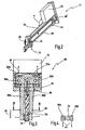
- an inventive joining system is generally designated 10.
- the joining system 10 has a robot 12.
- the robot 12 includes a stationary base 14 from which extend two hingedly connected arms 16, 18.
- a flange 20 is provided.
- Attached to the flange 20 is a joining system head, indicated generally at 22 in FIG.
- the joining system head 22 has a base plate 24 attached to the flange.
- Extending from the base plate 24 is an elongate carrier 26.
- the elongate carrier 26 has a first short support section 28 and an adjoining second elongated support section 30.
- the second support portion 30 is angled relative to the first support portion 28 by an angle ⁇ of 120 °.
- the angle ⁇ is preferably between 60 and 80 ° or 100 and 120 °.
- the axis of the second support portion 30 is designated 27 in FIG.
- a joining tool 32 is rotatably mounted about a rotation axis 34.
- the axis of rotation 34 is perpendicular to the axis 27 of the second support portion 30 and is aligned approximately parallel with the base plate 24 in the illustrated embodiment.
- the joining tool 32 serves to weld an element, in particular a welding stud 36, to a component, in particular a metal sheet 38.
- the joining system is structurally applicable to a variety of joining manners, a configuration of the joining system as a stud welding system or a short-arc arc welding system with a lift ignition is particularly preferable.
- the joining system is referred to as a stud welding system and the joining system head 22 as a stud welding head.
- the joining tool 32 is referred to as a welding tool 32.
- the welding tool 32 welds the bolts 36 to the component 38 in a linear movement (joining direction 40).
- the welding head 22 also has a control device 42.
- the control device 42 is provided at the beginning region of the elongated carrier 26 and is mounted in the illustrated embodiment on the first support portion 28, adjacent to the base plate 24.
- the control device 42 serves to drive the joining tool 32 and as an interface to higher-level control devices.
- the welding head 22 also has a feed device 44.
- the Zufilhr beautiful 44 serves to take over bolts with the shaft of a feed hose and provide at a transfer station 46.
- the feeder 44 is thus substantially formed as a tube or hose and extends along the elongate carrier 26.
- the transfer station 46 is located in a central region of the second support portion 30. In each case, an element for transfer provided to the welding tool 32. This element is designated in Fig. 1 with 36 ".
- the welding system 10 further includes a stationary base station 50.
- the base station 50 serves to provide the welding head 22 with energy for welding, and serves as a higher-level control device.
- the base station 50 is connected to a separating device 52.
- the separating device 52 serves to singulate bolts, which are generally delivered as bulk material, and to convey them individually via a hose 54 to the feed device 44.
- the separating device 52 usually has a compressed air unit in order to be able to convey the elements 36 pneumatically.
- a line 56 is shown in Fig. 1, which connects the base station 50 with the welding head 22.
- the line 56 is usually realized as a line system and includes lines for guiding the welding current, control lines, etc.
- FIG. 1 Also shown in FIG. 1 is a conduit 58 which connects the welding head 22 to the base 14 of the robot 12.
- the line 58 is optional and includes one or more control lines. By means of the control lines 58, the movements of the robot 12 can be coordinated with those of the welding tool 32.
- the base 14 of the robot 12 is connected to the base station 50 via a line 60. Accordingly, it is also possible that the vote between robot 12 and welding head 22 via the lines 60, 56 takes place.
- the lines 56, 58 are led to the control device 42, from which they are partially looped through to the welding tool 32 (for powering the units there), are used partly directly.
- the welding tool 32 has a housing 62 which is rotatably mounted on the axis of rotation 34.
- a joining drive device 64 in the form of a linear motor 64 is provided on the housing 62.
- the linear motor 64 serves to move a holding device 66 projecting from the housing 62 for holding a respective bolt 36 perpendicular to the axis of rotation 34.
- the linear motor 64 thus forms a lifting device for completing the lifting and diving movements in the context of a stud welding operation, as described in the introduction.
- a rotary drive 68 is provided at the end portion of the second support portion 30, which serves to rotate the welding tool 32 controlled in any angular positions with respect to the second support portion 30.
- the range of rotation is typically at least 270 °, usually 360 °.
- the rotary drive 68 serves on the one hand to rotate the welding tool 32 in a respective suitable welding position, one of which is shown in Fig. 1 in solid lines.
- An alternative welding position is indicated by dashed lines at 32 '. In the further welding position, the welding tool 32 'along a welding direction 40' used to weld a bolt 36 'on a non-illustrated component.
- the rotary drive 68 serves as a loading drive device.
- the welding tool 32 is rotated to a position which is shown in dashed lines in Fig. 1.
- the holding device 66 is aligned "aligned with the transfer station 46 and can take in this position a standing there bolt 36" and take over for a subsequent welding process.
- the loading drive device is formed solely by the rotary drive 68, for example an electric motor, variants thereof are also conceivable.
- the loading drive means may be formed by displacing the non-rotatable welding tool 32 on the carrier 26 longitudinally, for example. It is understood that then the transfer station 46 would have to be arranged at a different location.
- the welding tool 32 can be formed with very small dimensions. On the one hand, the welding tool 32 is spatially separated from the control device 42. On the other hand, the welding tool 32 is decoupled from the pneumatic bolt supply device. That is, on the welding tool 32 no pneumatic or hydraulic lines need to be flanged.
- the electrical supply of the linear motor 64 and / or the rotary drive 68 is comparatively easy to implement. The same applies to the operation of the holding device 66, provided that it is actively operated electrically.
- the welding tool 32 can therefore build short in the axial direction.
- the rotary drive 68 can be designed as an electric stepper motor with an accuracy of ⁇ 1 °, better still 0.5 °.
- the parameter specifications for the rotational movement are related to the welding program and to the second robot movement program.
- Each welding position has its own welding program and its own robot movement program.
- the parameter data By referring the parameter data to the individual welding and robot motion programs, it is ensured that, firstly, the bolt 36 is always perpendicular to the surface of the component 38, and second, that the welding tool 32 is in a position during the robot movement that provides the robot with the greatest possible freedom of movement the way to the welding position.
- the control of the rotational movement of the welding tool 32 can take place via the base station 50 and / or via the base 14 of the robot 12.
- the oblique bending of the second support section 30 with respect to the first support section 28 on the one hand offers an improved interference edge clearance.
- the feeder 44 is easier to realize because the bolts, as shown, are held by gravity and / or blast air at the transfer station 46.
- Fig. 1 it is further shown that the component 38 is designed as an angular component with a relatively small opening 70. Seen from the robot 12, the desired welding position is inside a cavity 72.
- the stud welding system 10 is particularly well suited to fulfill this task.
- the welding tool 32 can be rotated into a position in which it is largely flush with the second support section 30, for example the position 32 "in FIG. 1.
- the welding tool 32 After insertion into the cavity 72, the welding tool 32 is rotated into the welding position shown in solid lines. Previously, a bolt 36 is taken over by the transfer station 46, so that it is located in the holding device 66.
- the retainer 66 is preferably configured to release the welded bolt 36 in a direction transverse to the welding direction 40. Consequently, it is possible to turn the joining tool 32 back into the aligned position 32 "immediately after welding without the second support section 30 having to perform a movement in the welding direction 40. Once the aligned position 32" is reached, the second support section 30 can be pulled out through the opening 70 again. The robot 12 then guides the welding head 22 to the next welding position.
- the axis of rotation 34 forms for the robot 12 a further robot axis of rotation.
- the positioning at a welding position can thus be made easier. This is all the more true as the further axis of rotation is close to the welding position.
- Another advantage of the welding system 10 according to the invention results as follows.
- the welding head was a relevant interference edge. Therefore, in the prior art, no pneumatic valves have been provided on the welding head. However, this caused a very complicated wiring between the base station 50 and the welding head 22.
- the control device 42 Due to the physical separation of the control device 42 from the welding tool 32 on the welding head 22, the control device 42 itself is not disturbing edge relevant. Consequently, valves can be integrated in the control device 42 at the welding head 22, so that the number and complexity of the supply lines can be reduced. Since the control device 42 is provided on the welding head 22, no complicated electrical wiring between the welding head 22 and base station 50 is necessary.
- the supply lines 56 in a hose package only contain a welding cable, two auxiliary power supplies for the linear motor and a 24-volt supply for the control device, two optical fibers for the serial transmission of control and measurement data, and the supply hose 54.
- the hose package could also be supplemented by a protective gas supply or a blowing / suction line , for example for color marking.
- the hose package can therefore be less heavy, less warp-resistant and therefore safer.
- a further bolt can be conveyed from the separating device 52 via the hose 54 and the feed device 44 to the transfer station 46. This can be done while the welding tool 32 performs a stud welding operation.
- the welding tool 32 can be pivoted to the transfer station 46 and then pivoted to the correct position for the new welding position.
- elements to be welded Although basically any shape can be used as the elements to be welded, elements which can be supplied by compressed air, in particular rotationally symmetrical elements, are particularly suitable for being processed with the joining system according to the invention.
- the further welding position 32 ' may be, for example, an overhead position, such as the position 32' shown. This can be achieved without having to rotate the carrier 26. As a result, stresses on the feed cable and hoses are avoided.
- a rotary drive 68 'for rotating the welding tool 32 is not provided in the end region of the second support section 30, but in the area of the control device 42.
- the rotary movements of the rotary drive 68' are transmitted to the welding tool by means of a belt drive 80 32 transmitted.
- the belt drive 80 runs along the elongated carrier 26.
- the elongate carrier 26 is formed in the illustration of FIG. 2 by two parallel arms, between the end regions of the welding tool 32 is rotatably mounted.
- FIGS. 3 and 4 show an embodiment of a holding device 66.
- the holding device 66 has a housing 84, which has an opening 86 pointing downwards in the joining direction.
- the holding device 66 has two jaws 88A, 88B, which are mounted so as to be limitedly pivotable on the housing 84 and which are formed from a substantially inelastic material.
- the jaws 88A, 88B form a collet by allowing a member 36 to be clamped between the ends of the jaws 88A, 88B with a predetermined force.
- the jaws 88A, 88B are each integrally connected to a lever portion 92A, 92B. With respect to axles 90A, 90B on which the jaws 88A, 88B are mounted, the lever portions 92A, 92B extend in the other direction.
- the Lever sections 92A, 92B are compared to the joining direction 40 bent so that they overlap.
- the jaws 88A, 88B are thus moved away from each other to release the pin 36. This is shown for the jaw 88A in FIG. It can be seen that the jaw 88A completely releases the bolt 36 in the direction transverse to the joining direction 40 (ie out of the plane of the paper in FIG.
- the retainer 66 can be moved transversely to the joining direction 40 and perpendicular to the plane of the jaws 88A, 88B without touching the pin 36.
- the direction of movement of the jaws 88A, 88B in this process is indicated at 93 in FIG.
- an actuator 94 is provided, which is preferably electrically actuated.
- Actuator 94 actively opens and closes jaws 88A, 88B, respectively. It is understood that the actuator 94 must be designed for this purpose as a bidirectional drive.
- the active actuation of the jaws 88A, 88B has the advantage that the bolt 36 can be held with a defined force (e.g., 20 N).
- a defined force e.g. 20 N.
- the derivation of the clamping force from the elasticity of the individual fingers of the collet of the prior art is eliminated. Consequently, a much longer life can be achieved.
- the direction of actuation of the actuator 94 is shown at 96 in FIG.
- the jaws 88A, 88B are formed so that they can securely grasp the respective bolt 36. For this purpose, it may be useful to put suitable essays on the jaws 88A, 88B, which may be adapted to different bolts 36.
- a positioning pin 98 extends from the bottom of the housing 94, as shown in Fig. 3, a positioning pin 98 extends.
- the positioning pin or stop pin 98 is rigidly connected to the housing 84. It serves to ensure, upon acceptance of a bolt 36 from the transfer station 46, that the bolt 36 assumes a defined position with respect to the holding device 66, and as a stop to absorb the axial force during welding.
- the bidirectional active actuator may be formed by a pneumatic or hydraulic drive. Preferably, however, it is formed by a combination of two electromagnets or by an unregulated linear motor on the principle of 'moving coil' or 'moving permanent magnet'.
- the actuator 94 semi-active.
- the opening of the jaws 88A, 88B for example, by an electromagnet.
- suitably arranged springs cause a bolt 36 to be gripped by jaws 88A, 88B with a defined force.
- the jaws 88A and / or 88B are supplied with welding current which is conducted to the bolt 36.
- the defined force ensures a safe, low-wear power transfer.
- the jaws 88A, 88B are made of a conductive metal.
- the positioning pin 98 should be formed non-conductive or insulated against the housing 84.
- jaws which are designed to be elastic and which permit lateral insertion of the bolt 36 between them (along the direction 93) and the movement transverse to a welded-on bolt 36 release them without significant exercise of power.
- the longitudinal axis of the holding device 66 is designated 100.
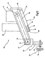
- FIGS. 5 and 6 show a further alternative embodiment of a welding tool 32.
- the welding tool 32 has a tool housing 102 on which a linear motor 104 of a joining drive device 64 is fixed.
- the axis of the linear motor 104 is shown at 105. It is shown that the axis 100 of the holding device 66 and the axis 105 of the linear motor 104 are spaced apart by a distance d.
- the holding device 66 is displaced out of the projection of the linear motor 104 in the joining direction. Thereby, it is possible, the holding device 66 and thus a held bolt 36 closer to an edge or a disturbing wall to position. Overall, this increases the flexibility of the welding head 22.
- the linear motor 104 has an anchor portion 106 which is connected to a transverse to the joining direction guide plate 108. From the guide plate 108 also extend two diagonally with respect to the linear motor 104 arranged guide rods 110, 112th
- the guide rods 110, 112 ensure that the guide plate 108 is guided without tilting.
- the holding device 66 extends from the underside of the guide plate 108.
- An actuator for actuating the holding device 66 may, for example, be formed on the top side of the guide plate 108 or integrated therein.
- the carrier 26 is formed of a comparatively solid support arm 116 and a parallel thereto extending, less massive clamping arm 118.
- the welding tool 32 is rotatably supported between the arms 116, 118 along the axis of rotation 34.
- power cables 120 are further indicated for supplying power to the jaws 88A, 88B.
- FIG. 7 Another alternative embodiment of a joining tool 32 is shown in FIG. 7.
- the welding tool 32 has a linear motor housing 122. On the tops of the guide rods 110, 112 flanges 123 are provided, respectively. Between the flanges 123 and the linear motor housing 122 compression springs 124 are arranged, which are formed around the guide rods 110, 112 around.
- the linear motor 104 is thus biased by the compression springs 124 so that the thus moving guide plate 108 is in the retracted, that is not extended position.
- a further compression spring 126 may be provided in the interior of the linear motor housing 122.
- a flap magnet 128 is articulated to an axis 130.
- the folding magnet 128 serves to push down the lever portions 92A, 92B to open the jaws 88.
- the lever portions 92 are biased by a tension spring 132 in the direction of the closed position of the jaws 88.
- a first embodiment of a transfer station 46 of the feeder 44 is shown.
- two opposite sensors 136 for example, a light barrier
- the feed device 44 is essentially formed by a tube or hose 138, which is bent in the region of the transfer station 46 inwardly.
- the bolts 36 are conveyed with the shaft forward from the separating device 52 through the feed device 44 therethrough. Consequently, the head of the bolt 36 abuts the crimping of the tube 138 and thus remains in the transfer station 46. In this case, the shank of the bolt 36 extends out of the tube 138.
- the holding device 66 can now be performed with the jaws 88A, 88B open towards the bolt 36 and grip the bolt 36. Subsequently, the holding device 66 is pivoted back again, in the illustration of Fig. 8 from the plane of the paper out. It is understood that at the transfer station 46, a suitable lateral recess in the tube 138 must be provided, which is not shown in detail in Fig. 8.
- FIG. 1 An alternative embodiment of a transfer station 46 'is shown in FIG.
- a tube 138 'of the feeder 44' is open towards the end.
- two clamping jaws 142 are rotatably mounted.
- the clamping jaws 142 are biased by means of two springs 144 in a position in which their insides obstruct the exit of a bolt 36 from the tube 138 '.
- the bolt 36 is thereby braked at a feed.
- a positioning lever 146 is pivoted laterally from the illustration shown in Fig. 9, to pass the bolt 36. Subsequently, the positioning lever 146 is pivoted, as shown at 147. As a result, the bolt 36 pushes apart the clamping jaws 142A, 142B and is displaced away from the tube 138 'until the head of the bolt 36 snaps into an annular recess 148.
- the annular recess 148 is formed by the inner sides of the clamping jaws 142A, 142B. In this position, the bolt 36 is held defined with a certain force.
- the holding device 66 can, as in FIG. 8, grasp the shank of the bolt 36 and pull it out laterally from the annular recess 148.
- this embodiment has the advantage that the bolt 36 is in the transfer station 46 'in a defined position and is held with a defined force, so that a secure gripping of the bolt 36 is ensured by means of the holding device 66 , It is understood that suitable sensors for detecting a bolt 36 in the transfer position can also be provided at the transfer station 46 '.
- the bolts 36 are conveyed via a pipe 138" into a bolt receiver 154 of a pivotable rotary segment 152.
- the rotation segment 152 is rotatable about an axis of rotation 153 which is oriented transversely to the axis of the tube 138 "and transversely to the orientation of the pin 36 in the transfer position.
- the rotary segment 152 is in a transfer position. In this position, a pneumatic cylinder 156 is used to press the bolt 36 by means of a plunger 158 between two jaws 160, between which the bolt 36 is then held defined. Thereafter, the rotary segment 152 is rotated back to receive another pin 36 in the receiving position shown in phantom with the tube 138 ''
- This embodiment has the advantage that the pins 36 can be fed through the tube 138 'at high speed. Thus, short cycle times can be achieved.
- FIG. 170 Another embodiment of a welding head according to the invention is indicated generally at 170 in FIG.
- the welding head 170 has at the front end of the carrier 26, a welding tool 171, which has only one rotatably mounted on the carrier 26 housing and a holding device 172 fixed thereto.
- the holding device 172 has two jaws 174, between which a bolt 36 is held so that it is aligned tangentially to a circumference about the axis of rotation 34 around. In other words, a joining process is not along a rectilinear motion but along a circular path.
- the corresponding guide direction is shown in FIG. 12 as pitch circle 176.
- the rotary drive 175 thus serves at the same time as a loading drive by being pivoted to take over a respective new bolt 36 from a transfer station 180 of a feed device 178. In the feed device 178, the bolts 36 are not fed one after the other but side by side, so that the holding device 172 can grasp the bolts 36 transversely to their own extension.
- the feeder 178 may either have suitable means for converting the longitudinal movement from the singulator 52 into the transverse orientation shown in FIG. As an alternative to this, it is also possible to advance the bolts 36 already from the singling device 52 in the transverse position.
- a magazine 186 provided on the carrier 26 is schematically provided in FIG. 12.
- the magazine 186 can serve as a storage magazine for a plurality of bolts 36, which are then transferred by means of a suitable integrated separating device to the feed device 178 and the transfer station 180.
Claims (20)
- Tête de système d'assemblage (22) pouvant être fixée sur un bâti mobile (12), en particulier sur un robot (12), et pouvant être amenée dans une position d'assemblage à l'aide de ce bâti mobile, comprenant- un dispositif de maintien (66) pour un élément (36) qui doit être monté sur un composant (38),- un dispositif d'entraînement d'assemblage (64) destiné à déplacer le dispositif de maintien (66) en vue d'effectuer l'assemblage le long d'une direction d'assemblage (40), et- un dispositif d'amenée (44) permettant d'amener des éléments (36) à un poste de transfert (46) dans la tête de système d'assemblage (22),caractérisée en ce que
un dispositif de commande (42), destiné à commander le dispositif d'entraînement d'assemblage (64) de la tête d'assemblage (22), est disposé de façon espacée du dispositif de maintien (66) et du dispositif d'entraînement d'assemblage (64), de manière que le dispositif de maintien (66) et le dispositif d'entraînement d'assemblage (64) forment un outil d'assemblage (32) présentant des dimensions réduites, et en ce que des moyens (68) sont prévus pour transférer les éléments (36) acheminés au poste de transfert (46) du dispositif d'amenée (44), vers le dispositif de maintien (66), depuis l'avant de celui-ci. - Tête de système d'assemblage selon la revendication 1, caractérisée en ce que l'outil d'assemblage (32) est monté au niveau d'une partie terminale d'une poutrelle allongée (26) se projetant vers l'avant.
- Tête de système d'assemblage selon la revendication 2, caractérisée en ce que l'outil d'assemblage (32) est monté de façon mobile au niveau d'une partie terminale de la poutrelle (26), et en ce qu'un dispositif d'entraînement de chargement (68) est conçu pour amener l'outil d'assemblage (32) jusqu'à un poste de transfert (46) en vue de transférer un élément (36) au dispositif de maintien (66).
- Tête de système d'assemblage selon la revendication 3, caractérisée en ce que l'outil d'assemblage (32) est monté de façon pivotante au niveau d'une partie terminale de la poutrelle (26), et en ce que le dispositif d'entraînement de chargement (68) est conçu pour faire pivoter l'outil d'assemblage (32) vers le poste de transfert (44).
- Tête de système d'assemblage selon la revendication 3 ou 4, caractérisée en ce que le dispositif d'entraînement de chargement (68) comporte un moteur (68) qui est disposé au niveau d'une partie terminale de la poutrelle (26).
- Tête de système d'assemblage selon la revendication 3 ou 4, caractérisée en ce que le dispositif d'entraînement de chargement (68) comprend un moteur (68') et une transmission (80) montés au niveau du dispositif de commande (42), la transmission transmettant les mouvements du moteur (68') à l'outil d'assemblage (32).
- Tête de système d'assemblage selon la revendication 6, caractérisée en ce que le moteur (68') est un moteur de rotation (68'), et que la transmission (80) est une transmission par moyens de traction (80).
- Tête de système d'assemblage selon l'une des revendications 1 à 7, caractérisée en ce que le dispositif d'entraînement d'assemblage (64) est constitué d'un moteur électrique linéaire (64).
- Tête de système d'assemblage selon la revendication 8, caractérisée en ce que l'axe longitudinal (105) du dispositif d'entraînement d'assemblage (64) et l'axe longitudinal (100) du dispositif de maintien (66) sont espacés parallèlement l'un à l'autre.
- Tête de système d'assemblage selon l'une des revendications 1 à 9, caractérisée en ce que le dispositif de maintien (66) comprend une multitude de mâchoires (88) qui sont disposées autour de l'axe longitudinal (100) du dispositif de maintien (66) et peuvent être déplacées en se rapprochant et en s'écartant les unes des autres, de façon à retenir ou à relâcher un élément (36).
- Tête de système d'assemblage selon la revendication 10, caractérisée en ce que le dispositif de maintien (66) comprend deux mâchoires (88A, 88B).
- Tête de système d'assemblage selon l'une des revendications 10 ou 11, caractérisée en ce que les mâchoires (88) peuvent être écartées les unes des autres à un point tel que le dispositif de maintien (66) puisse relâcher l'élément (36) en étant retiré de l'élément (36) dans une direction oblique par rapport à la direction d'assemblage (40).
- Tête de système d'assemblage selon la revendication 12, caractérisée en ce que les mâchoires (88) peuvent être écartées les unes des autres à un point tel que le dispositif de maintien (66) puisse relâcher l'élément (36) en effectuant une rotation autour d'un axe de rotation (34), en s'éloignant de l'élément (36), cet axe étant dirigé transversalement à la direction d'assemblage (40).
- Tête de système d'assemblage selon l'une des revendications 10 à 13, caractérisée en ce qu'un actionneur (94) des mâchoires est prévu, qui ouvre et/ou ferme les mâchoires (88) de façon active.
- Tête de système d'assemblage selon l'une des revendications 10 à 14, caractérisée en ce que les mâchoires (88) sont configurées ou montées de façon élastique (132) de manière à pouvoir être rapprochées et/ou écartées les unes des autres de façon passive.
- Tête de système d'assemblage selon l'une des revendications 2 à 15, caractérisée en ce que le poste de transfert (46) est monté sur la poutrelle allongée (26).
- Tête de système d'assemblage selon l'une des revendications 1 à 16, caractérisée en ce que le dispositif d'amenée (44) comprend un magasin (186) pour les éléments (36).
- Système d'assemblage (10) comprenant un robot (12) pouvant être déplacé dans au moins deux axes de coordonnées, et une tête de système d'assemblage (22) fixée sur le robot (12), caractérisé en ce que la tête de système d'assemblage (22) est une tête de système d'assemblage (22) selon l'une des revendications 1 à 17.
- Système d'assemblage selon la revendication 18, caractérisé en ce qu'un dispositif stationnaire d'individualisation (52) achemine des éléments détachés individuels (36) vers le dispositif d'amenée (44) de la tête de système d'assemblage (22).
- Procédé d'amenée d'éléments (36) depuis une unité stationnaire (52) vers une tête mobile (22) de système d'assemblage selon l'une des revendications 1 à 17, et de montage d'éléments (36) ainsi amenés, au moyen de la tête de système d'assemblage (22), sur des composants (38), où un élément (36") est amené depuis l'unité stationnaire (52) vers la tête mobile (22) de système d'assemblage, pendant que la tête de système d'assemblage (22) monte un élément déjà amené (36) sur un composant (38).
Applications Claiming Priority (2)
| Application Number | Priority Date | Filing Date | Title |
|---|---|---|---|
| DE10223154A DE10223154A1 (de) | 2002-05-16 | 2002-05-16 | Fügesystemkopf, Fügesystem und Verfahren zum Zuführen und Fügen von Elementen |
| DE10223154 | 2002-05-16 |
Publications (2)
| Publication Number | Publication Date |
|---|---|
| EP1362660A1 EP1362660A1 (fr) | 2003-11-19 |
| EP1362660B1 true EP1362660B1 (fr) | 2007-12-05 |
Family
ID=29265387
Family Applications (1)
| Application Number | Title | Priority Date | Filing Date |
|---|---|---|---|
| EP03010431A Expired - Lifetime EP1362660B1 (fr) | 2002-05-16 | 2003-05-09 | Tête, système et méthode pour l'approvisionnement et la fixation d'éléments |
Country Status (5)
| Country | Link |
|---|---|
| US (2) | US7291802B2 (fr) |
| EP (1) | EP1362660B1 (fr) |
| JP (1) | JP2003334661A (fr) |
| AT (1) | ATE380088T1 (fr) |
| DE (2) | DE10223154A1 (fr) |
Families Citing this family (17)
| Publication number | Priority date | Publication date | Assignee | Title |
|---|---|---|---|---|
| DE10223154A1 (de) * | 2002-05-16 | 2003-11-27 | Newfrey Llc | Fügesystemkopf, Fügesystem und Verfahren zum Zuführen und Fügen von Elementen |
| DE10229690B4 (de) * | 2002-06-26 | 2010-03-25 | Newfrey Llc, Newark | Vorrichtung und Verfahren zum Kurzzeit-Lichtbogenschweißen |
| DE10333415A1 (de) * | 2003-07-17 | 2005-02-03 | Newfrey Llc, Newark | Fügevorrichtung |
| DE102005038189A1 (de) * | 2005-08-12 | 2007-02-15 | Daimlerchrysler Ag | Mobiler Bolzen-Schweisskopf |
| DE102005041534A1 (de) * | 2005-08-31 | 2007-03-01 | Newfrey Llc, Newark | Verfahren und Vorrichtung zum Zuführen von Verbindungselementen zu einem Verarbeitungsgerät |
| DE102005044367A1 (de) | 2005-09-09 | 2007-03-15 | Newfrey Llc, Newark | Fügesystemkopf, Fügesystem und Verfahren zum Zuführen und Fügen von Elementen |
| DE102005044362A1 (de) * | 2005-09-09 | 2007-03-15 | Newfrey Llc, Newark | Fügewerkzeug und Verfahren zum Fügen eines Elementes auf ein Bauteil |
| US7511245B2 (en) | 2005-09-12 | 2009-03-31 | Nelson Stud Welding, Inc. | Stud welding apparatus with composite cable |
| US20070267392A1 (en) * | 2006-05-22 | 2007-11-22 | Newfrey Llc | Welding workpiece movement sensing system |
| WO2009023511A1 (fr) * | 2007-08-10 | 2009-02-19 | Fanuc Robotics America, Inc. | Outil magnétique pour robots |
| EP2070628B1 (fr) * | 2007-12-13 | 2017-03-29 | Caterpillar Inc. | Appareil de soudure pour clou |
| DE102009018755A1 (de) | 2009-04-27 | 2010-10-28 | Newfrey Llc, Newark | Fügekopfanordnung und Gleitkontaktanordnung hierfür |
| CN103659094B (zh) * | 2012-09-21 | 2016-05-04 | 上海拖拉机内燃机有限公司 | 机器人点焊和螺柱焊焊接系统 |
| CN103831511B (zh) * | 2012-11-22 | 2016-04-06 | 沈阳工业大学 | 一种螺柱焊自动送钉机构 |
| JP6415917B2 (ja) * | 2014-09-26 | 2018-10-31 | 日本ファブテック株式会社 | スタッドボルト溶接装置 |
| EP3593932A1 (fr) * | 2018-07-11 | 2020-01-15 | MAGNA STEYR Fahrzeugtechnik AG & Co KG | Système de soudage de goujon avec un dispositif de port pour porter une pluralité de parties formées |
| DE102021104140A1 (de) * | 2021-02-22 | 2022-08-25 | Bayerische Motoren Werke Aktiengesellschaft | Vorvereinzelungsvorrichtung, Fügevorrichtung und Verfahren zum Betreiben einer Fügevorrichtung |
Family Cites Families (53)
| Publication number | Priority date | Publication date | Assignee | Title |
|---|---|---|---|---|
| US2549804A (en) | 1949-11-01 | 1951-04-24 | Graham Mfg Corp | Welding boot |
| US2727123A (en) | 1952-08-18 | 1955-12-13 | Gregory Ind Inc | Stud welder |
| US2790066A (en) | 1954-08-13 | 1957-04-23 | Gregory Ind Inc | Stud welder |
| FR1488981A (fr) | 1965-07-21 | 1967-07-21 | Perfectionnements au soudage à l'arc électrique en flux protecteur gazeux | |
| US3379868A (en) * | 1965-12-10 | 1968-04-23 | Gen Electric | Electric discharge projection lamp |
| US3636341A (en) * | 1969-11-14 | 1972-01-18 | Gen Electric | Lamp and housing assembly |
| US3917971A (en) * | 1974-03-22 | 1975-11-04 | Gte Sylvania Inc | Metal halide discharge lamp having a thermally insulative end coating |
| US3989920A (en) | 1975-05-15 | 1976-11-02 | Massachusetts Institute Of Technology | Underwater stud welding gun |
| JPS5322821U (fr) * | 1976-08-05 | 1978-02-25 | ||
| US4306137A (en) | 1978-05-16 | 1981-12-15 | Trw Inc. | Method and apparatus for conducting smut-free stud welding |
| JPS5554278A (en) * | 1978-10-16 | 1980-04-21 | Nippon Doraibuitsuto Kk | Stud welding machine |
| JPS5989669U (ja) * | 1982-12-09 | 1984-06-18 | 株式会社東芝 | スタツドウエルドガンのスタツド供給装置 |
| JPS6134583A (ja) * | 1984-07-26 | 1986-02-18 | シャープ株式会社 | 照明装置 |
| US4620079A (en) * | 1985-10-03 | 1986-10-28 | Usm Corporation | Stud welding device |
| JPH0790370B2 (ja) * | 1986-05-30 | 1995-10-04 | 日本ドライブイツト株式会社 | 自動操作型スタツド溶接装置 |
| JPH0329018Y2 (fr) * | 1986-07-11 | 1991-06-20 | ||
| JPS6341369U (fr) * | 1986-09-05 | 1988-03-18 | ||
| DE3702481A1 (de) * | 1987-01-28 | 1988-08-11 | Philips Patentverwaltung | Gasentladungslampe |
| US4792655A (en) * | 1987-10-20 | 1988-12-20 | Emhart Industries, Inc. | Stud welding system feeding device |
| US4924368A (en) * | 1989-01-06 | 1990-05-08 | Duro-Test Corporation | Fluorescent lamp with protective shield |
| US5068511A (en) * | 1990-07-13 | 1991-11-26 | Emhart Industries, Inc. | Stud welding tool |
| DE69117027T2 (de) | 1990-12-18 | 1996-09-05 | Emhart Inc | Lichtbogenschweissen eines Bolzens |
| DE4200199A1 (de) | 1992-01-07 | 1993-07-08 | Emhart Inc | Verfahren zum elektrischen verschweissen zweier schweissteile |
| JP2596517Y2 (ja) | 1992-07-17 | 1999-06-14 | ポップリベット・ファスナー株式会社 | スタッド溶接機の制御装置 |
| KR970006293B1 (ko) * | 1992-10-06 | 1997-04-25 | 캐논 가부시끼가이샤 | 원고 조명 장치 |
| CA2153417A1 (fr) | 1993-01-07 | 1994-07-21 | Stuart Edmund Blacket | Outils d'assemblage ameliores |
| US5252802A (en) | 1993-01-27 | 1993-10-12 | Trw Inc. | Apparatus for welding a stud to a workpiece |
| US5291379A (en) * | 1993-04-01 | 1994-03-01 | Jem Dong Lu | Protective lamp-shade |
| US5317124A (en) | 1993-07-12 | 1994-05-31 | Emhart Inc. | Stud welding |
| JP2869322B2 (ja) * | 1993-12-17 | 1999-03-10 | 日本スタッドウェルディング株式会社 | 自動スタッド溶接におけるスタッドの高速供給方法及びその装置 |
| DE4400350C2 (de) * | 1994-01-08 | 1997-08-07 | Bettermann Obo Ohg | Bolzenschweißvorrichtung |
| JP2824735B2 (ja) * | 1994-04-02 | 1998-11-18 | 好高 青山 | 部品供給装置 |
| CH688186A5 (de) | 1994-10-03 | 1997-06-13 | Ifa Internationale Finanzansta | Schweissverfahren zum Verbinden einer Komponente mit einem Werkstueck und Vorrichtung zum Ausfuehren des Verfahrens. |
| US6215085B1 (en) | 1994-10-18 | 2001-04-10 | Emhart Inc. | Stud welding device |
| US5502291A (en) | 1994-11-07 | 1996-03-26 | Emhart Inc. | Stud welder |
| DE19524490B4 (de) | 1995-07-05 | 2005-06-09 | Newfrey Llc, Newark | Verfahren zum Verschweißen von Schweißbolzen mit einem Werkstück |
| JPH09288993A (ja) * | 1996-04-19 | 1997-11-04 | Sharp Corp | 照明装置及びこの照明装置を利用した表示装置 |
| US5798494A (en) * | 1996-06-24 | 1998-08-25 | Aoyama; Yoshitaka | Welding apparatus |
| DE19625886B4 (de) | 1996-06-27 | 2007-03-22 | Newfrey Llc, Newark | Elektrische Schweißvorrichtung und Verfahren zum Aufschweißen eines Befestigungselementes |
| US6147724A (en) * | 1997-04-04 | 2000-11-14 | Hitachi, Ltd. | Back light system for minimizing non display area of liquid crystal display device |
| DE19727411A1 (de) * | 1997-06-27 | 1999-01-07 | Emhart Inc | Verfahren sowie ein Befestigungsmittel zur Ausbildung einer schweißtechnischen Verbindung zwischen einem Befestigungsmittel und einer Struktur |
| DE29719744U1 (de) | 1997-11-06 | 1998-02-26 | Emhart Inc | Transportvorrichtung für längliche mit einem Kopf und einem Schaft ausgebildete Bauteile |
| US5981896A (en) | 1998-08-26 | 1999-11-09 | Electric Power Research Institute, Inc. | Apparatus and method for creating dry underwater welds |
| DE19925628A1 (de) | 1999-06-05 | 2000-12-07 | Emhart Inc | Hubzündungsschweißverfahren mit Reinigungsstufe |
| US6060690A (en) | 1999-06-24 | 2000-05-09 | Caterpillar Inc. | Welding nozzle for improved gas coverage |
| DE19933185A1 (de) | 1999-07-15 | 2001-01-18 | Fev Motorentech Gmbh | Sensoranordnung zur Erfassung von Gasanteilen in partikelbehafteten Gasströmungen |
| US6388224B1 (en) * | 1999-12-28 | 2002-05-14 | Abb T&D Technology Ltd. | Systems for robotic stud arc welding without ferrule |
| DE10007837A1 (de) | 2000-02-21 | 2001-08-23 | Nelson Bolzenschweis Technik G | Verfahren zum Positionieren eines Schweißbolzens und Bolzenschweißkopf |
| US7164224B2 (en) * | 2000-12-14 | 2007-01-16 | Sharp Kabushiki Kaisha | Backlight having discharge tube, reflector and heat conduction member contacting discharge tube |
| EP1956637A3 (fr) * | 2001-03-19 | 2008-09-03 | Fujitsu Limited | Appareil d' eclairage et afficheur |
| DE10223147A1 (de) | 2002-05-16 | 2003-11-27 | Newfrey Llc | Fügesystemkopf, Fügesystem und Verfahren zum Zuführen und Fügen von Elementen |
| DE10223154A1 (de) | 2002-05-16 | 2003-11-27 | Newfrey Llc | Fügesystemkopf, Fügesystem und Verfahren zum Zuführen und Fügen von Elementen |
| US6968030B2 (en) * | 2003-05-20 | 2005-11-22 | General Electric Company | Method and apparatus for presenting multiple pre-subject filtering profiles during CT data acquisition |
-
2002
- 2002-05-16 DE DE10223154A patent/DE10223154A1/de not_active Withdrawn
-
2003
- 2003-05-09 DE DE50308716T patent/DE50308716D1/de not_active Expired - Lifetime
- 2003-05-09 AT AT03010431T patent/ATE380088T1/de not_active IP Right Cessation
- 2003-05-09 EP EP03010431A patent/EP1362660B1/fr not_active Expired - Lifetime
- 2003-05-13 US US10/436,894 patent/US7291802B2/en not_active Expired - Fee Related
- 2003-05-16 JP JP2003138514A patent/JP2003334661A/ja active Pending
-
2007
- 2007-05-30 US US11/807,717 patent/US8653402B2/en active Active
Also Published As
| Publication number | Publication date |
|---|---|
| DE10223154A1 (de) | 2003-11-27 |
| DE50308716D1 (de) | 2008-01-17 |
| EP1362660A1 (fr) | 2003-11-19 |
| ATE380088T1 (de) | 2007-12-15 |
| US8653402B2 (en) | 2014-02-18 |
| JP2003334661A (ja) | 2003-11-25 |
| US20040037634A1 (en) | 2004-02-26 |
| US7291802B2 (en) | 2007-11-06 |
| US20070251923A1 (en) | 2007-11-01 |
Similar Documents
| Publication | Publication Date | Title |
|---|---|---|
| EP1362661B1 (fr) | Tête, système et méthode d'approvisionnement et de fixation d'éléments | |
| EP1362660B1 (fr) | Tête, système et méthode pour l'approvisionnement et la fixation d'éléments | |
| DE102005044367A1 (de) | Fügesystemkopf, Fügesystem und Verfahren zum Zuführen und Fügen von Elementen | |
| DE602004010978T2 (de) | Handhabungsroboter mit Greifer zur Handhabung von Werkstücken mit unterschiedlichen Formen | |
| DE102008018428A1 (de) | Setzgerät, Verfahren und Vorrichtungen zum Zuführen von Befestigungselementen | |
| EP2607029A1 (fr) | Système de changement d'outils | |
| WO2006103263A1 (fr) | Dispositif pour acheminer de petites pieces de montage, comme des rivets, des vis, des boulons a souder ou similaires | |
| DE102009039104A1 (de) | Greifer, Verfahren zum Wechseln wenigstens eines Aufsatzbackens eines Greifers, sowie frei programmierbarer Manipulator mit einem solchen Greifer | |
| EP0760770A1 (fr) | Procede et dispositif permettant d'amener, de maintenir en position et d'usiner les pieces d'une carrosserie de vehicule | |
| DE102011113832A1 (de) | Verfahren und Vorrichtung zum Zuführen von Fügeelementen | |
| WO2006063630A1 (fr) | Unite d'introduction et procede pour introduire un element dans une unite de traitement | |
| DE102018121968A1 (de) | Werkzeugmaschine zum Bearbeiten von Werkstücken | |
| EP1277540B1 (fr) | Station d'usinage | |
| EP3763557A1 (fr) | Raccordement automatisé d'une prise de charge à une interface de charge d'un véhicule | |
| DE102014107533A1 (de) | Umkonfigurierbare Robotergreiforgananordnung | |
| EP4275801A1 (fr) | Poste d'application de produit d'étanchéité et système de montage pour relier des composants | |
| DE102017101619A1 (de) | Werkstückklemmvorrichtung und Bearbeitungssystem mit einer Werkstückklemmvorrichtung | |
| DE102009019130A1 (de) | Fügekopfanordnung und Fügeverfahren | |
| AT412081B (de) | Spannrahmen und bearbeitungsstation mit spannrahmen | |
| DE102007012981B3 (de) | Schweißkopf | |
| DE102015219514A1 (de) | Greifvorrichtung für einen Manipulator und Verfahren zum gleichzeitigen Greifen von zumindest zwei Objekten | |
| DE2225441C2 (de) | Blindnietvorrichtung zum Setzen von Hohlnieten | |
| DE102007011188B4 (de) | Vorrichtung und ein Verfahren zum Handhaben von Schmiedeteilen | |
| DE102019204729A1 (de) | Beladungseinrichtung und Verfahren zum automatisierten Beladen einer Reifenbaumaschine mit Wulstkernen sowie Reifenbaumaschine | |
| EP0449281A1 (fr) | Méthode et appareil pour le montage des parts dans des trous |
Legal Events
| Date | Code | Title | Description |
|---|---|---|---|
| PUAI | Public reference made under article 153(3) epc to a published international application that has entered the european phase |
Free format text: ORIGINAL CODE: 0009012 |
|
| AK | Designated contracting states |
Kind code of ref document: A1 Designated state(s): AT BE BG CH CY CZ DE DK EE ES FI FR GB GR HU IE IT LI LU MC NL PT RO SE SI SK TR |
|
| AX | Request for extension of the european patent |
Extension state: AL LT LV MK |
|
| 17P | Request for examination filed |
Effective date: 20031029 |
|
| RAP1 | Party data changed (applicant data changed or rights of an application transferred) |
Owner name: NEWFREY LLC |
|
| AKX | Designation fees paid |
Designated state(s): AT BE BG CH CY CZ DE DK EE ES FI FR GB GR HU IE IT LI LU MC NL PT RO SE SI SK TR |
|
| 17Q | First examination report despatched |
Effective date: 20050215 |
|
| GRAP | Despatch of communication of intention to grant a patent |
Free format text: ORIGINAL CODE: EPIDOSNIGR1 |
|
| GRAS | Grant fee paid |
Free format text: ORIGINAL CODE: EPIDOSNIGR3 |
|
| GRAA | (expected) grant |
Free format text: ORIGINAL CODE: 0009210 |
|
| AK | Designated contracting states |
Kind code of ref document: B1 Designated state(s): AT BE BG CH CY CZ DE DK EE ES FI FR GB GR HU IE IT LI LU MC NL PT RO SE SI SK TR |
|
| REG | Reference to a national code |
Ref country code: GB Ref legal event code: FG4D Free format text: NOT ENGLISH |
|
| REG | Reference to a national code |
Ref country code: IE Ref legal event code: FG4D Free format text: LANGUAGE OF EP DOCUMENT: GERMAN |
|
| REG | Reference to a national code |
Ref country code: CH Ref legal event code: EP |
|
| REF | Corresponds to: |
Ref document number: 50308716 Country of ref document: DE Date of ref document: 20080117 Kind code of ref document: P |
|
| GBT | Gb: translation of ep patent filed (gb section 77(6)(a)/1977) |
Effective date: 20080306 |
|
| PG25 | Lapsed in a contracting state [announced via postgrant information from national office to epo] |
Ref country code: ES Free format text: LAPSE BECAUSE OF FAILURE TO SUBMIT A TRANSLATION OF THE DESCRIPTION OR TO PAY THE FEE WITHIN THE PRESCRIBED TIME-LIMIT Effective date: 20080316 Ref country code: SE Free format text: LAPSE BECAUSE OF FAILURE TO SUBMIT A TRANSLATION OF THE DESCRIPTION OR TO PAY THE FEE WITHIN THE PRESCRIBED TIME-LIMIT Effective date: 20080305 Ref country code: NL Free format text: LAPSE BECAUSE OF FAILURE TO SUBMIT A TRANSLATION OF THE DESCRIPTION OR TO PAY THE FEE WITHIN THE PRESCRIBED TIME-LIMIT Effective date: 20071205 |
|
| PG25 | Lapsed in a contracting state [announced via postgrant information from national office to epo] |
Ref country code: FI Free format text: LAPSE BECAUSE OF FAILURE TO SUBMIT A TRANSLATION OF THE DESCRIPTION OR TO PAY THE FEE WITHIN THE PRESCRIBED TIME-LIMIT Effective date: 20071205 Ref country code: SI Free format text: LAPSE BECAUSE OF FAILURE TO SUBMIT A TRANSLATION OF THE DESCRIPTION OR TO PAY THE FEE WITHIN THE PRESCRIBED TIME-LIMIT Effective date: 20071205 |
|
| NLV1 | Nl: lapsed or annulled due to failure to fulfill the requirements of art. 29p and 29m of the patents act | ||
| PG25 | Lapsed in a contracting state [announced via postgrant information from national office to epo] |
Ref country code: CZ Free format text: LAPSE BECAUSE OF FAILURE TO SUBMIT A TRANSLATION OF THE DESCRIPTION OR TO PAY THE FEE WITHIN THE PRESCRIBED TIME-LIMIT Effective date: 20071205 |
|
| ET | Fr: translation filed | ||
| PG25 | Lapsed in a contracting state [announced via postgrant information from national office to epo] |
Ref country code: RO Free format text: LAPSE BECAUSE OF FAILURE TO SUBMIT A TRANSLATION OF THE DESCRIPTION OR TO PAY THE FEE WITHIN THE PRESCRIBED TIME-LIMIT Effective date: 20071205 Ref country code: SK Free format text: LAPSE BECAUSE OF FAILURE TO SUBMIT A TRANSLATION OF THE DESCRIPTION OR TO PAY THE FEE WITHIN THE PRESCRIBED TIME-LIMIT Effective date: 20071205 |
|
| PG25 | Lapsed in a contracting state [announced via postgrant information from national office to epo] |
Ref country code: PT Free format text: LAPSE BECAUSE OF FAILURE TO SUBMIT A TRANSLATION OF THE DESCRIPTION OR TO PAY THE FEE WITHIN THE PRESCRIBED TIME-LIMIT Effective date: 20080505 |
|
| REG | Reference to a national code |
Ref country code: IE Ref legal event code: FD4D |
|
| PLBE | No opposition filed within time limit |
Free format text: ORIGINAL CODE: 0009261 |
|
| STAA | Information on the status of an ep patent application or granted ep patent |
Free format text: STATUS: NO OPPOSITION FILED WITHIN TIME LIMIT |
|
| PG25 | Lapsed in a contracting state [announced via postgrant information from national office to epo] |
Ref country code: IE Free format text: LAPSE BECAUSE OF FAILURE TO SUBMIT A TRANSLATION OF THE DESCRIPTION OR TO PAY THE FEE WITHIN THE PRESCRIBED TIME-LIMIT Effective date: 20071205 Ref country code: DK Free format text: LAPSE BECAUSE OF FAILURE TO SUBMIT A TRANSLATION OF THE DESCRIPTION OR TO PAY THE FEE WITHIN THE PRESCRIBED TIME-LIMIT Effective date: 20071205 |
|
| 26N | No opposition filed |
Effective date: 20080908 |
|
| BERE | Be: lapsed |
Owner name: NEWFREY LLC Effective date: 20080531 |
|
| PG25 | Lapsed in a contracting state [announced via postgrant information from national office to epo] |
Ref country code: MC Free format text: LAPSE BECAUSE OF NON-PAYMENT OF DUE FEES Effective date: 20080531 |
|
| REG | Reference to a national code |
Ref country code: CH Ref legal event code: PL |
|
| PG25 | Lapsed in a contracting state [announced via postgrant information from national office to epo] |
Ref country code: CH Free format text: LAPSE BECAUSE OF NON-PAYMENT OF DUE FEES Effective date: 20080531 Ref country code: EE Free format text: LAPSE BECAUSE OF FAILURE TO SUBMIT A TRANSLATION OF THE DESCRIPTION OR TO PAY THE FEE WITHIN THE PRESCRIBED TIME-LIMIT Effective date: 20071205 Ref country code: LI Free format text: LAPSE BECAUSE OF NON-PAYMENT OF DUE FEES Effective date: 20080531 Ref country code: GR Free format text: LAPSE BECAUSE OF FAILURE TO SUBMIT A TRANSLATION OF THE DESCRIPTION OR TO PAY THE FEE WITHIN THE PRESCRIBED TIME-LIMIT Effective date: 20080306 |
|
| PG25 | Lapsed in a contracting state [announced via postgrant information from national office to epo] |
Ref country code: BE Free format text: LAPSE BECAUSE OF NON-PAYMENT OF DUE FEES Effective date: 20080531 |
|
| PG25 | Lapsed in a contracting state [announced via postgrant information from national office to epo] |
Ref country code: BG Free format text: LAPSE BECAUSE OF FAILURE TO SUBMIT A TRANSLATION OF THE DESCRIPTION OR TO PAY THE FEE WITHIN THE PRESCRIBED TIME-LIMIT Effective date: 20080305 |
|
| PG25 | Lapsed in a contracting state [announced via postgrant information from national office to epo] |
Ref country code: CY Free format text: LAPSE BECAUSE OF FAILURE TO SUBMIT A TRANSLATION OF THE DESCRIPTION OR TO PAY THE FEE WITHIN THE PRESCRIBED TIME-LIMIT Effective date: 20071205 |
|
| PG25 | Lapsed in a contracting state [announced via postgrant information from national office to epo] |
Ref country code: AT Free format text: LAPSE BECAUSE OF NON-PAYMENT OF DUE FEES Effective date: 20080509 |
|
| PG25 | Lapsed in a contracting state [announced via postgrant information from national office to epo] |
Ref country code: HU Free format text: LAPSE BECAUSE OF FAILURE TO SUBMIT A TRANSLATION OF THE DESCRIPTION OR TO PAY THE FEE WITHIN THE PRESCRIBED TIME-LIMIT Effective date: 20080606 Ref country code: LU Free format text: LAPSE BECAUSE OF NON-PAYMENT OF DUE FEES Effective date: 20080509 |
|
| PG25 | Lapsed in a contracting state [announced via postgrant information from national office to epo] |
Ref country code: TR Free format text: LAPSE BECAUSE OF FAILURE TO SUBMIT A TRANSLATION OF THE DESCRIPTION OR TO PAY THE FEE WITHIN THE PRESCRIBED TIME-LIMIT Effective date: 20071205 |
|
| PGFP | Annual fee paid to national office [announced via postgrant information from national office to epo] |
Ref country code: IT Payment date: 20140526 Year of fee payment: 12 |
|
| PG25 | Lapsed in a contracting state [announced via postgrant information from national office to epo] |
Ref country code: IT Free format text: LAPSE BECAUSE OF NON-PAYMENT OF DUE FEES Effective date: 20150509 |
|
| REG | Reference to a national code |
Ref country code: FR Ref legal event code: PLFP Year of fee payment: 14 |
|
| REG | Reference to a national code |
Ref country code: FR Ref legal event code: PLFP Year of fee payment: 15 |
|
| REG | Reference to a national code |
Ref country code: FR Ref legal event code: PLFP Year of fee payment: 16 |
|
| PGFP | Annual fee paid to national office [announced via postgrant information from national office to epo] |
Ref country code: FR Payment date: 20190410 Year of fee payment: 17 |
|
| PGFP | Annual fee paid to national office [announced via postgrant information from national office to epo] |
Ref country code: GB Payment date: 20200429 Year of fee payment: 18 |
|
| PG25 | Lapsed in a contracting state [announced via postgrant information from national office to epo] |
Ref country code: FR Free format text: LAPSE BECAUSE OF NON-PAYMENT OF DUE FEES Effective date: 20200531 |
|
| PGFP | Annual fee paid to national office [announced via postgrant information from national office to epo] |
Ref country code: DE Payment date: 20210413 Year of fee payment: 19 |
|
| GBPC | Gb: european patent ceased through non-payment of renewal fee |
Effective date: 20210509 |
|
| PG25 | Lapsed in a contracting state [announced via postgrant information from national office to epo] |
Ref country code: GB Free format text: LAPSE BECAUSE OF NON-PAYMENT OF DUE FEES Effective date: 20210509 |
|
| REG | Reference to a national code |
Ref country code: DE Ref legal event code: R119 Ref document number: 50308716 Country of ref document: DE |
|
| PG25 | Lapsed in a contracting state [announced via postgrant information from national office to epo] |
Ref country code: DE Free format text: LAPSE BECAUSE OF NON-PAYMENT OF DUE FEES Effective date: 20221201 |