EP4275801A1 - Poste d'application de produit d'étanchéité et système de montage pour relier des composants - Google Patents
Poste d'application de produit d'étanchéité et système de montage pour relier des composants Download PDFInfo
- Publication number
- EP4275801A1 EP4275801A1 EP23172100.2A EP23172100A EP4275801A1 EP 4275801 A1 EP4275801 A1 EP 4275801A1 EP 23172100 A EP23172100 A EP 23172100A EP 4275801 A1 EP4275801 A1 EP 4275801A1
- Authority
- EP
- European Patent Office
- Prior art keywords
- connector
- sealant
- sealant application
- drill
- application station
- Prior art date
- Legal status (The legal status is an assumption and is not a legal conclusion. Google has not performed a legal analysis and makes no representation as to the accuracy of the status listed.)
- Pending
Links
- 239000000565 sealant Substances 0.000 title claims abstract description 155
- 238000005304 joining Methods 0.000 title claims description 4
- 238000005553 drilling Methods 0.000 claims abstract description 80
- 238000003754 machining Methods 0.000 claims abstract description 51
- 238000000034 method Methods 0.000 claims description 25
- 238000012546 transfer Methods 0.000 claims description 25
- 230000008569 process Effects 0.000 claims description 24
- 238000012545 processing Methods 0.000 claims description 22
- 239000012636 effector Substances 0.000 claims description 19
- 230000032258 transport Effects 0.000 description 7
- 238000000926 separation method Methods 0.000 description 5
- 238000004519 manufacturing process Methods 0.000 description 4
- 238000013459 approach Methods 0.000 description 2
- 239000000356 contaminant Substances 0.000 description 2
- 238000013461 design Methods 0.000 description 2
- 230000007246 mechanism Effects 0.000 description 2
- 230000003287 optical effect Effects 0.000 description 2
- 238000005299 abrasion Methods 0.000 description 1
- 230000008901 benefit Effects 0.000 description 1
- 238000010276 construction Methods 0.000 description 1
- 238000011157 data evaluation Methods 0.000 description 1
- 230000001419 dependent effect Effects 0.000 description 1
- 238000006073 displacement reaction Methods 0.000 description 1
- 238000005516 engineering process Methods 0.000 description 1
- 230000005484 gravity Effects 0.000 description 1
- 230000006872 improvement Effects 0.000 description 1
- 230000003993 interaction Effects 0.000 description 1
- 239000007788 liquid Substances 0.000 description 1
- 239000003550 marker Substances 0.000 description 1
- 238000007781 pre-processing Methods 0.000 description 1
- 238000003908 quality control method Methods 0.000 description 1
- 238000005507 spraying Methods 0.000 description 1
- 230000007704 transition Effects 0.000 description 1
Images

Classifications
-
- B—PERFORMING OPERATIONS; TRANSPORTING
- B23—MACHINE TOOLS; METAL-WORKING NOT OTHERWISE PROVIDED FOR
- B23P—METAL-WORKING NOT OTHERWISE PROVIDED FOR; COMBINED OPERATIONS; UNIVERSAL MACHINE TOOLS
- B23P19/00—Machines for simply fitting together or separating metal parts or objects, or metal and non-metal parts, whether or not involving some deformation; Tools or devices therefor so far as not provided for in other classes
- B23P19/04—Machines for simply fitting together or separating metal parts or objects, or metal and non-metal parts, whether or not involving some deformation; Tools or devices therefor so far as not provided for in other classes for assembling or disassembling parts
-
- B—PERFORMING OPERATIONS; TRANSPORTING
- B05—SPRAYING OR ATOMISING IN GENERAL; APPLYING FLUENT MATERIALS TO SURFACES, IN GENERAL
- B05B—SPRAYING APPARATUS; ATOMISING APPARATUS; NOZZLES
- B05B13/00—Machines or plants for applying liquids or other fluent materials to surfaces of objects or other work by spraying, not covered by groups B05B1/00 - B05B11/00
- B05B13/02—Means for supporting work; Arrangement or mounting of spray heads; Adaptation or arrangement of means for feeding work
- B05B13/0221—Means for supporting work; Arrangement or mounting of spray heads; Adaptation or arrangement of means for feeding work characterised by the means for moving or conveying the objects or other work, e.g. conveyor belts
- B05B13/0228—Means for supporting work; Arrangement or mounting of spray heads; Adaptation or arrangement of means for feeding work characterised by the means for moving or conveying the objects or other work, e.g. conveyor belts the movement of the objects being rotative
-
- B—PERFORMING OPERATIONS; TRANSPORTING
- B05—SPRAYING OR ATOMISING IN GENERAL; APPLYING FLUENT MATERIALS TO SURFACES, IN GENERAL
- B05C—APPARATUS FOR APPLYING FLUENT MATERIALS TO SURFACES, IN GENERAL
- B05C13/00—Means for manipulating or holding work, e.g. for separate articles
- B05C13/02—Means for manipulating or holding work, e.g. for separate articles for particular articles
-
- B—PERFORMING OPERATIONS; TRANSPORTING
- B21—MECHANICAL METAL-WORKING WITHOUT ESSENTIALLY REMOVING MATERIAL; PUNCHING METAL
- B21J—FORGING; HAMMERING; PRESSING METAL; RIVETING; FORGE FURNACES
- B21J15/00—Riveting
- B21J15/10—Riveting machines
- B21J15/30—Particular elements, e.g. supports; Suspension equipment specially adapted for portable riveters
- B21J15/32—Devices for inserting or holding rivets in position with or without feeding arrangements
-
- B—PERFORMING OPERATIONS; TRANSPORTING
- B23—MACHINE TOOLS; METAL-WORKING NOT OTHERWISE PROVIDED FOR
- B23P—METAL-WORKING NOT OTHERWISE PROVIDED FOR; COMBINED OPERATIONS; UNIVERSAL MACHINE TOOLS
- B23P19/00—Machines for simply fitting together or separating metal parts or objects, or metal and non-metal parts, whether or not involving some deformation; Tools or devices therefor so far as not provided for in other classes
- B23P19/001—Article feeders for assembling machines
- B23P19/007—Picking-up and placing mechanisms
-
- B—PERFORMING OPERATIONS; TRANSPORTING
- B23—MACHINE TOOLS; METAL-WORKING NOT OTHERWISE PROVIDED FOR
- B23P—METAL-WORKING NOT OTHERWISE PROVIDED FOR; COMBINED OPERATIONS; UNIVERSAL MACHINE TOOLS
- B23P19/00—Machines for simply fitting together or separating metal parts or objects, or metal and non-metal parts, whether or not involving some deformation; Tools or devices therefor so far as not provided for in other classes
- B23P19/04—Machines for simply fitting together or separating metal parts or objects, or metal and non-metal parts, whether or not involving some deformation; Tools or devices therefor so far as not provided for in other classes for assembling or disassembling parts
- B23P19/06—Screw or nut setting or loosening machines
Definitions
- the present description relates to manufacturing technology, in particular automated machines, which can be used in a manufacturing process.
- the description relates to a sealant application station and an assembly tool as well as an assembly system which has such a sealant application station and/or such an assembly tool.
- Modern assembly processes are characterized by the fact that manual assembly processes are often replaced by an automated solution.
- the automated solution usually involves the use of appropriate machines that carry out the steps to be carried out in a predefined order.
- Key criteria for evaluating an automated solution in an assembly process include the stability of the automated process, the reproducibility of the individual work steps and the work results, and the verifiability of the quality achieved in the automated processes, for example by means of integrated quality control.
- a sealant application station and an assembly tool are described in connection with this description.
- the sealant application station and the assembly tool can be used together in an assembly system.
- the sealant application station and the assembly tool can also be used separately from one another. This means that the sealant application station can also be used with another assembly tool.
- the assembly tool can also be used with or without a sealant application station.
- both the sealant application station and the assembly tool are described because these two units can interact with one another and because functions of one unit are partly described with reference to functions of the other unit. In this respect, both the sealant application station and the assembly tool are described in the remainder of the description because it serves to understand the overall context.
- a sealant application station for applying sealant to a connector for joining a workpiece.
- the sealant application station has a feed, a discharge, a holding unit, a gripper, a drive unit and a sealant application unit.
- the feed is designed to provide a connector for the sealant application station to supply.
- the removal is designed to remove the connector from the sealant application station.
- the holding unit is arranged to hold the connector after feeding over the feed.
- the gripper is designed to grip the connector held by the holding unit.
- the drive unit is designed to rotate the gripper about an axis of rotation.
- the sealant application unit is designed to apply a sealant to the connector while the drive unit rotates the gripper about the axis of rotation.
- the holding unit is movable to expose a discharge opening after the sealant application unit has applied a sealant to the connector.
- the sealant application station can be used, for example, in the production of workpieces, in particular for production steps that include pre-processing of connectors. This involves the application of sealants to a connector, which is used in a subsequent processing step to connect or join two components into one component.
- the connector can be, for example, an impact rivet or a screw rivet, which is applied with sealant before it is inserted into an opening in the components in order to connect them to one another and to seal the connection point.
- the components and the component can be, for example, fuselage components of aircraft that must be connected to one another in such a way that they are connected in an airtight manner at the connection point. This also applies to the places where the connectors are arranged. For this reason, the connectors are applied with a sealant before they are inserted into the corresponding openings of the components.
- a two-component connector can be used as a sealant, which despite being very hard has high elasticity and maintains its strength properties over a comparatively large temperature range, for example from -60°C to +100°C.
- the supply and the discharge can be designed as a standard hose system, via which a connector can be transported using vacuum or compressed air. Transporting connectors via a hose system is generally known. Details of this will not be discussed further here.
- the connector is transported via the hose system and assumes a specific orientation.
- a connector in the form of a rivet is preferably transported with the rivet head first (in the direction of movement). The head of the connector thus hits the holding unit and is then gripped in this orientation by the gripper. The connector maintains this basic orientation for further transport via the discharge opening.
- the discharge opening is preferably arranged along a feed direction of the connector, so that the connector, after it has been introduced via the feed and held and rotated by the gripper, passes into the discharge opening as soon as the holding unit releases the discharge opening.
- This has the advantage that the connector is removed from the feed, applied with sealant, and continues on its way towards further processing. No complex sharing mechanisms are necessary. Rather, the connector is dispensed from the feeder, first stopped in its movement by the holding unit and then gripped by the gripper and set into a rotational movement in front of the sealant application unit.
- the connector is preferably rotated through 360° so that sealant is applied to it in its entire circumferential direction. All that is required for this process is a drive that rotates the gripper.
- the gripper does not necessarily have to carry out a translational movement.
- the holding unit can assume one of two states: in a first state, the holding unit blocks the discharge opening and holds a connector that is output from the feeder. In this position of the connector, the connector can be gripped and rotated by the gripper; in a second state the holding unit releases the discharge opening, for example by the holding unit performing a pivoting movement or a linear movement, thereby releasing the discharge opening; The connector can then be placed into the discharge opening and is transported further for the next processing steps.
- the sealant application unit applies the sealant to the connector, for example by squeezing or spraying the sealant out of an opening in the sealant application unit.
- the sealant application unit can be moved to a predeterminable distance from the surface of the connector.
- the sealant is preferably applied in a liquid state to an area of the surface of the connector, for example by means of an opening or nozzle arranged on the sealant application unit.
- sealant is applied to the connector in the circumferential direction, preferably around the entire circumference and over a certain area in the longitudinal direction.
- the sealant application station further comprises a transfer station, which is arranged at an outlet end of the feed and is mechanically coupled to the gripper.
- the drive unit is coupled to the transfer station in such a way that movement of the drive unit is transmitted to the transfer station, whereby the gripper is rotated about the axis of rotation.
- the drive unit is coupled to the transfer station via a drive belt.
- the drive unit can be, for example, an electric motor or another suitable drive.
- the transfer station is rotatably arranged at one end of the feeder.
- the gripper can be rotated so that in a processing step (ie when applying sealant to a connector) performs a 360° clockwise rotation and, in a subsequent processing step (ie, applying sealant to the next connector), performs a 360° counterclockwise rotation.
- a processing step ie when applying sealant to a connector
- a subsequent processing step ie, applying sealant to the next connector
- the sealant application unit is movable in the radial direction of the connector in order to assume a predeterminable distance from the connector.
- the sealant application unit can be brought to a suitable distance from the surface of the connector before this surface is applied with sealant.
- this distance can be set or varied depending on the sealant used and depending on the size of the surface area exposed to the sealant.
- the sealant application station has a sensor unit which is designed to detect the distance between the sealant application unit and the connector or its surface.
- the detected distance can be transmitted to a controller of the sealant application station, whereby the controller is able to set the distance between the sealant application unit and the surface of the connector to a desired value by appropriately controlling a drive of the sealant application unit.
- the gripper has at least two gripping fingers, which can be adjusted to a size of the connector in order to be able to grip connectors with different dimensions.
- the at least two gripping fingers are designed to carry out a gripping movement.
- an actuator e.g. an electromechanical/hydraulic/pneumatic drive
- the actuator can be controlled so that it stops the gripping movement when a predetermined gripping force applied to the connector is reached.
- the gripping fingers may be coated or prepared on a gripping surface to grip the connector such that the connector is securely held between the gripping fingers for the duration of the processing steps being performed.
- the gripping fingers can also be brought from an open position into the gripping position with the aid of a mechanical spring or clamping element. An actuator is therefore only necessary to open the gripping fingers, whereas the gripping fingers carry out the gripping movement through the spring or clamping element when the actuator no longer holds the gripping fingers in the open state.
- the gripper holds the connector such that a central axis of the connector coincides with the rotation axis of the gripper.
- the connector does not experience any translational displacement when the gripper rotates about the axis of rotation. Rather, the connector remains in the same place and is only rotated about its central axis, which is aligned with the rotation axis of the gripper.
- the sealant application unit has assumed a predetermined distance from the surface of the connector, this distance is maintained as the gripper rotates with the connector, which is particularly true for rotationally symmetrical connectors.
- the sealant is therefore applied at the same distance over the entire circumference of the connector, thereby applying the sealant in a uniform amount along the entire circumference.
- the holding unit is movable transversely to a transport direction of the connector or to a longitudinal axis of the connector when it is in the position held by the gripper in order to release the discharge opening.
- the holding unit can, for example, be moved from a first state in which it blocks the discharge opening to a second state in which it releases the discharge opening. After the connector loaded with sealant has been transported away, the holding unit is usually moved from the second state back to the first state.
- An electromechanical drive unit, a pneumatic unit, a hydraulic unit, a magnetic unit or another type of drive can be used for this.
- the holding unit can perform a linear movement or a pivoting movement when moving from the first state to the second state.
- the holding unit has an opening that can be brought into overlap with the discharge opening of the sealant application station. In this state, the opening of the holding unit is under the connector and the connector is no longer held in position and falls through the opening of the holding unit into the discharge opening.
- the opening in the holding unit can in particular have the same cross section as the discharge opening.
- an assembly tool for connecting two components has an end effector.
- the end effector has a drill spindle with a drill and a setting finger.
- the drilling spindle is designed to rotate the drill about a machining axis.
- the setting finger is designed to have a connector made of one Pick up the feed and bring it into a processing position.
- the drilling spindle is designed to be moved in the longitudinal direction along the machining axis.
- the setting finger is configured to be pivotally moved and to position the connector so that the connector is axially aligned with the drill.
- the drilling spindle is designed to insert the connector into the components by moving along the machining axis and thereby connect them to one another.
- the assembly tool described here is characterized by its simplicity.
- the drilling spindle is moved linearly along a machining axis.
- the drilling spindle can be moved in both directions along the machining axis, for example by an electromechanical drive such as an electric motor or other types of drive described herein (pneumatic, hydraulic, magnetic, etc.).
- the drilling spindle can therefore be moved towards or away from the two components to be connected along the machining axis. This allows the drill spindle to be moved so that the drill drills a hole in the components.
- the drill is returned, i.e. the drill spindle is moved away from the drilled components.
- the drill rotates around its longitudinal axis as usual.
- the longitudinal axis of the drill coincides with the machining axis of the drilling spindle, which means that the drill rotates around the machining axis during the drilling process.
- the drill spindle preferably moves in such a way that the drill completely penetrates both components to be connected.
- the drill is then moved out of the drilled hole by moving in the opposite direction along the machining axis and takes a predetermined distance from the drilled components.
- the processing position of the connector is characterized by the fact that in the processing position the connector is axially aligned with the drill. This means that a center axis of the connector coincides with the center axis of the drill. Although the drill and the connector are spaced apart from one another along the machining axis or arranged one behind the other along the machining axis, they are both located on the machining axis. As a result, in this position the connector is also aligned with the hole drilled by the drill.
- the connector is, for example, circular or rotationally symmetrical at least in sections (in the longitudinal direction) and the circular or rotationally symmetrical longitudinal section has the same or a slightly larger diameter than the drill.
- the connector In the processing position, the connector is also aligned with the hole in the components made by the drill. If the drilling spindle is now moved again along the machining axis in the direction of the components to be connected, the connector can be inserted into the hole drilled by the drill.
- This approach allows both to drill a hole in the components to be connected and to insert a connector into the hole drilled by the drill with a single drilling spindle and with a linear movement along a machining axis in both directions. This greatly reduces the mechanical complexity of the structure and the processing time.
- the drilling spindle assumes a corresponding distance from the components to be connected so that the setting finger with the connector can be pivoted between the drill and the components to be connected.
- the assembly tool described here can be used in a system together with the sealant application station.
- the sealant application station provides a connector loaded with sealant is ready to the assembly tool, for example via a feed that is designed as a vacuum or compressed air transport hose.
- the connector is then used in the assembly tool as described to connect components to be connected together.
- the assembly tool can also be supplied with a connector in another way; the sealant application station described above is not necessarily necessary for this.
- the setting finger is connected to the drilling spindle via a joint, the joint being designed so that the setting finger can be pivoted into the machining position in front of the drill and pivoted out of the machining position.
- the joint that connects the setting finger to the drill spindle is, for example, a swivel or rotation joint.
- the joint is arranged, for example, on a housing of the drill spindle.
- the setting finger can be pivoted in the joint using an actuator.
- the actuator can be a drive as described above with reference to the linear movement of the drilling spindle along the machining axis.
- the joint allows pivoting movement about a single axis.
- the setting finger therefore has a simple structural design because the Pivoting movement into the processing position and no complex movement has to be carried out out of the processing position. However, it is of course possible for the setting finger to also carry out a different movement pattern during this movement into the processing position or out of the processing position, which is adapted to the respective requirements.
- the connector and the drill lie on a common axis in the processing position and are arranged one behind the other on this common axis.
- the drill and the connector are, for example, arranged relative to one another in such a way that a vertical projection (along the machining axis 319) of the drill and the connector onto the workpiece surface lie one above the other or lie in the same place.
- the common axis of the connector and the drill runs parallel to the machining axis or coincides with the machining axis.
- the assembly tool further has kinematics in the form of a swivel arm, with the drilling spindle being arranged on the kinematics.
- the kinematics can, for example, be designed as a so-called six-axis swivel arm.
- the drilling spindle can be moved along the surface of the components to be connected in order to connect the drilling spindle to a new one after a connector has been placed in a drilled hole Bring the working position where a hole is to be drilled and a connector is to be placed.
- the drilling spindle Even if the drilling spindle is arranged on the kinematics in order to be brought to a new working position, the drilling spindle only carries out a movement along the machining axis at the respective working positions.
- the drilling spindle is moved along the machining axis towards the components, is then moved away from the components, then the setting finger with the connector is pivoted into the machining position and the drilling spindle is moved again along the machining axis towards the components in order to Insert the connector into the drilled hole.
- the drilling spindle is then moved away from the inserted connector, for example by first moving the drilling spindle away from the components along the machining axis and then using the kinematics to move the drilling spindle to the next working position.
- the assembly tool has a control and a sensor unit.
- the sensor unit is designed to detect a relative position of the drilling spindle in relation to the two components to be connected and to transmit it to the control.
- the control is designed to cause a movement of the drilling spindle based on the detected relative position of the drilling spindle with respect to the components to be connected.
- the sensor unit can, for example, have one or more optical sensors which are arranged on the drilling spindle.
- the sensors can also be arranged on other elements of the assembly tool.
- the sensors may be easier to detect the relative position of the drill spindle to the components to be connected because the relative position of the sensors to the drill spindle is fixed.
- the optical sensors are designed to detect their surroundings.
- the relative position of the drill spindle to the components to be connected can be recorded using certain markers on the components to be connected.
- the control is designed to control a drive for positioning the drilling spindle based on the relative position of the drilling spindle and the workpiece (components to be connected).
- the control can also be designed to control a drive for the rotation of the drill, for example depending on the distance between the drill spindle and the workpiece.
- the control can be designed to control both the linear drive of the drilling spindle for movement along the machining axis to the workpiece or away from the workpiece and the kinematics for moving the drilling spindle to the next working position.
- the functions of controlling the sealant application station and the functions of controlling the assembly tool can be performed by a single controller.
- a mounting system is specified.
- the assembly system includes a sealant application station as described herein and an assembly tool.
- the assembly tool can be the assembly tool described herein.
- sealant application station and assembly tool described herein may be used together in an assembly system to connect components together.
- a sealant is applied to the connector and the sealant-applied connector is passed on to the assembly tool, where it can be connected or joined together in a connection or joining process to be used to connect components.
- the assembly system can be used, for example, in the assembly of aircraft parts.
- several individual sections of an aircraft skin can be connected to one another with the assembly tool, using sealant-loaded connectors from the sealant application station described herein.
- sealant-loaded connectors from the sealant application station described herein.
- sealant application station can also be used independently of the assembly tool in an assembly system to apply a sealant to a connector.
- assembly tool can also be used independently of the sealant application station in an assembly system to connect two or more components to one another.
- connectors that are coated with sealant can be used in the same way as connectors that are not coated with sealant.
- the connectors can basically be transferred to the assembly tool in any way.
- the sealant application station is connected to the assembly tool for feeding a connector with a single feed hose, the single feed hose being configured to feed connectors with different dimensions to the assembly tool.
- connectors with different dimensions can be fed to the assembly tool via the single feed hose, it is sufficient to use a single feed hose to connect the sealant application station to the assembly tool. So can For example, connectors of different diameters and/or different lengths and/or different shapes (in the case of a song, the shape refers to the shape of the shaft and the head) are fed via the individual feed hose. This further reduces the complexity of the assembly system because a separate supply hose is not provided for each variant of the connector.
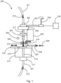
- Fig. 1 shows a sealant application station 200.
- the sealant application station 200 is supplied with a connector 215 via a hose system 101.
- the connector 215 is subjected to the work steps described below in the sealant application station 200 and transferred to the hose system 201 for further processing.
- the sealant application station 200 initially has a transfer station 202.
- the connector 215 is fed to the sealant application station 200 via the hose system 101 and the transfer station 202.
- the transfer station 202 brings the connector 215 into the sealant application station 200.
- the sealant application station 200 has a rotation unit 240, which is coupled to a gripper 205.
- the rotation unit 240 can be set in rotation by a drive unit 204 via a drive belt 203, whereby the gripper 205 is also set in rotation about the axis of rotation 217, wherein the rotation can take place in both directions 207 about the axis of rotation 217.
- the gripper 205 has a plurality of gripping fingers 206 which grip the connector 215.
- a connector 215 is supplied via the hose system 101 and the transfer station 202 and hits the holding unit 210.
- the holding unit 210 can be designed, for example, as a stop plate.
- the connector 215 is axially aligned with the axis of rotation 217, i.e. a central axis or longitudinal axis of the connector 215 coincides with the axis of rotation 217, and the connector is gripped by the gripping fingers 206 of the gripper 205.
- the drive unit 204 causes the rotation unit 240 and the gripper 205 to rotate via the drive belt 203, whereby the connector 215 is also rotated about the rotation axis 217.
- the functions of the sealant application station 200 are controlled by a controller 230.
- the controller 230 is also designed to control a movement of the holding unit 210 and the sealant application unit 208.
- the connector 215 is rotated about the axis of rotation 217.
- a sealant is applied to a portion of the surface of the connector with the sealant application unit 208 215 applied.
- the sealant application unit 208 can be moved radially in the direction of the connector 215 and assume a predetermined distance from the connector 215.
- the sealant is applied to the connector 215 via an opening or nozzle 218.
- the sealant is pressed out with a path-controlled squeezing force 209.
- the connector 215 While the sealant is being applied to the connector 215, the connector 215 preferably rotates through 360°, thereby applying the sealant over the entire circumference of the connector 215.
- a sensor unit 250 is arranged to detect the distance between the sealant application unit 208 and the connector 215.
- the sensor unit 250 can also be designed to detect a position and orientation of the connector 215 in order to enable gripping of the connector 215 with the gripper 205.
- the holding unit 210 is moved to release the discharge opening 214 in the mounting block 213.
- the holding unit 210 can be moved to the right to move the opening 219 in the holding unit so that the opening 219 lies above the discharge opening 214 and the connector 215 into the transfer unit 211 field, where the connector 215 is fed to the hose system 201.
- the holding unit 210 can also be moved to the left in order to release the discharge opening 214.
- the sealant application station 200 is preferably set up so that gravity brings the connector 215 from the transfer station 202 into the intended position on the holding unit 210 and brings the connector 215 to the transfer unit 211 as soon as the discharge opening 214 is released from the holding unit 210.
- the function of the sealant application station can be described as follows: the connectors 215 are removed within a hose system 101, 201, handed over to a sealant application unit 208 in order to provide the connector 215 with sealant 220, and handed over again to the hose system for further transport.
- the connector 215 is transported to the sealant application station 200, for example by means of compressed air, and is axially fixed in a fixed position by a horizontally movable slide (i.e. by the holding unit 210).
- the connector 215 is gripped with a radially gripping gripper 205 and its gripping fingers 206 (eg in the form of a parallel jaw gripper).
- the gripper 205 is attached to a rotation unit 240, which now begins to rotate through 360°, together with the connector 215 and the gripper.
- a sealant application unit 208 is delivered to the corresponding connector 215 by means of sensors 250 and either assumes a predetermined distance from the connector 215 or rests on the surface of the connector 215.
- the sealant application unit 208 has, for example, a sealant cartridge which is pressed out using a motor.
- the sealant is conveyed from the sealant cartridge to the connector 215 by means of a cannula.
- the sealant is applied to the connector at a transition between the cylindrical shaft and the head of the connector. The sealant is therefore protected against abrasion at this point during further transport through the hose system 201.
- the application of the sealant starts at the beginning of the rotation 207 about the axis of rotation 217 and ends after the rotation is completed.
- the gripper 205 now releases the connector 215 by releasing the gripping fingers so that the connector 215 remains freely on the horizontally movable slide 210 again.
- the slide 210 is now moved horizontally and the connector 215 falls axially back into the hose system 201.
- the connector 215 is guided axially through the opening 219 and discharge opening 214 by the gripper 205 with the mounted gripping fingers 206.
- the sealant After the sealant is applied to the connector and not to the workpiece to be machined, the sealant can be applied specifically and sparingly and it is ensured that the sealant is also at the point where the surface of the connector 215 with the machined workpiece is in contact.
- the sealant application station 200 described here is therefore positioned in a hose system 101, 201 supplied with compressed air and a connector 215 is supplied with sealant while it is transported to a device for further processing.
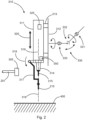
- Fig. 2 shows an end effector 310 of an assembly tool.
- the end effector 310 has a drilling spindle 311, which can be moved toward or away from a workpiece 400 to be machined in a direction of movement 320 along a machining axis 319.
- the drill spindle 311 is used to drill a hole in the workpiece 400 to be machined and to insert the connector 215 into the drilled hole. In these two steps, only a linear movement is carried out in both directions 320 along the machining axis 319 and the drilling spindle in particular does not have to be repositioned laterally along the surface of the workpiece 400.
- the end effector 310 can, for example, be used together with the sealant application station 200 Fig. 2 be used.
- the connector 215 is transported from the sealant application station 200 to the end effector 310 via the hose system 201.
- the end of the hose system 201 runs onto a transfer station 305.
- the connector 215 is delivered to a vacuum setting finger 317.
- the setting finger 317 holds the connector 215 in position using negative pressure/vacuum.
- the setting finger 317 can accommodate different connectors and be moved into a working position of the setting finger 317 via a pivot unit or a joint 318.
- the drilling spindle 311 has a controller 325 and a sensor unit 350.
- the drilling spindle 311 is coupled to a guide element or guide rails 312 via a carriage 313.
- a drive unit (not shown), which can be designed as a spindle drive, the drilling spindle 311 can be moved in both directions 320 along the machining axis 319. During this movement, the drilling spindle moves toward or away from the workpiece 400.
- the drive unit is controlled by the controller 325.
- the drill spindle has a drill chuck 314 and a drill 315.
- the drill 315 is positioned so that its longitudinal axis or central axis coincides with the machining axis 319.
- any drill 315 can be used, which is designed to drill a hole in the workpiece 400.
- the drill spindle 311 is moved toward the workpiece 400 until the drill has reached a desired depth in the workpiece 400.
- the drilling spindle 311 is then linearly moved away from the workpiece 400 along the machining axis 319 so that the drill is brought to a corresponding distance from the surface of the workpiece 400. Now the setting finger 317 can pivot into the processing position together with the received connector 215.
- the connector 215 In the machining position, the connector 215 is axially aligned with the drill 315 and the center axis of the connector 215 coincides with the center axis of the drill, with the connector 215 disposed along the machining axis 319 between the drill and the workpiece.
- the drill spindle 311 can be moved again toward the workpiece 400 with the connector 215 so arranged to insert the connector 215 into the hole drilled by the drill.
- the connector is released by the setting finger and the drill spindle is moved to a new working position.
- the drilling spindle 311 is connected to a kinematics 330.
- the kinematics 330 is designed to move the drilling spindle 311 from the current working position to a new working position after carrying out the steps described above.
- the sensor units 350 can detect the position of the drill spindle 311 relative to the workpiece 400 and transmit corresponding position information to the controller 325.
- the controller 325 can then control the kinematics 330 accordingly to bring the drilling spindle to the desired working position in order to then drill a hole there again and place a connector.
- the kinematics 330 is, for example, a construction with several joints, each of which can be moved about at least one axis.
- the kinematics 330 has, for example, three joints 331, 332, 333, each of which can be pivoted or rotated about an axis.
- the kinematics 330 can of course have further joints, not shown, in order to position the drill spindle 311 as desired.
- the kinematics 330 is only used to move the drill spindle 311 to a new working position.
- the working position here is understood to be the position of the drilling spindle along the surface of the workpiece 400, this working position being achieved in particular by a lateral movement of the drilling spindle, which, however, does not exclude other movement patterns of the kinematics 330.
- the drilling spindle 311 moves to drill the hole in the workpiece 400 and place the connector 215 in the hole only along the machining axis 319, which, for example, relates to a surface of the workpiece 400 runs orthogonally.
- a vacuum-applied setting unit 317 takes over the connector 215 from the hose system 201.
- the setting unit 317 is pivoted into a position so that it protrudes laterally from the drilling spindle 311 at least not between the drill and the workpiece located. From this position, in which the setting unit 317 receives the connector 215, the setting unit can be pivoted between the drill and the workpiece after the drill has drilled a hole in the workpiece.
- the hose system 201 leads the connector 215 loaded with sealant head first to the transfer station 305. At this point, the setting unit 317 takes over the connector 215.
- the connector for example a rivet, places its head on the setting unit 317 and is by means of Negative pressure or vacuum is sucked into the setting unit 317 and held.
- the transfer station 305 is moved away from the setting unit 317 so that the setting unit can perform a pivoting movement together with the connector to bring the connector between the drill and the workpiece.
- the connector can be inserted orthogonally into the borehole located in the workpiece by moving the drilling spindle 311 towards the workpiece along the machining axis 319.
- the vacuum in the setting unit 317 is now released, whereby the connector 215 is released, and the drill spindle 311 is moved away from the workpiece and moves to the new working position.
- measured values and machine data recorded by the sensor unit 350 can be transmitted to the controller 325 in order to evaluate and display the drilling and setting quality of a connection.
- the sensor unit can, for example, detect a movement profile of the drilling spindle along the machining axis 319 together with a drive power required to move the drilling spindle along the machining axis 319. This makes it possible to show the force with which the hole was drilled and the force with which the connector was inserted into the hole. From this data, conclusions can be drawn about the quality and strength of the connection produced.
- the sensor unit 350 can also be used to correct this working position after the drill spindle has moved to a working position to be carried out.
- the sensor units 350 can detect the relative position between the drilling spindle and the surface of the workpiece and correct this relative position if necessary.
- the sensor units 350 can, for example, detect a marker/pre-drill/tacking rivet on the surface of the workpiece 400 and thereby draw conclusions about the relative position between the drilling spindle and the workpiece.
- the drilling spindle can have one or more outlets for compressed air, through which compressed air is emitted when the drilling spindle approaches the surface of the workpiece in order to free the surface of the workpiece from contaminants.
- the contaminants can also be vacuumed off the surface of the workpiece. This operation can be carried out in particular after drilling a hole in the workpiece and before placing the connector in the drilled hole.
- the drilling spindle may have a foot which rests on the surface of the workpiece when drilling a hole and placing a connector into the workpiece.
- the foot can be placed on the surface of the workpiece using pneumatic cylinders and/or kinematics 330 and exert a process force or holding force on the workpiece 400 to fix the workpiece 400 for the drilling and setting steps of the connector 215.
- the drill spindle can be moved relative to the base along the machining axis 319 to drill the hole and seat the connector.
- the outlets for compressed air can also be arranged so that they clean a support surface of the foot before placing it on the surface of the workpiece.
- the drill spindle After drilling the hole in the workpiece 400 and placing the connector in the hole, the drill spindle is not activated.
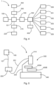
- Fig. 3 shows a schematic representation of an end effector 310 with a pressure foot 321.
- the perspective of Fig. 3 is chosen so that the setting finger 317 is at the front in the viewing direction, which is why the setting finger 317 is shown in dashed lines.
- the joint 318 including the setting finger 317, the drill chuck 314 and the drill 315, as well as the function of the setting finger 317 for placing the connector 215 reference is made to the previous description, in particular to Fig. 2 .
- the pressure foot 321 is arranged in the axial extension of the drilling spindle 311 in the direction of the workpiece 400.
- the pressure foot 321 is coupled to a piston rod 323 via a cylinder 322.
- the piston rod 323 By means of the piston rod 323, the pressure foot 321 can be moved along the machining axis 319 and along the direction of movement 324 in order to place the end effector 310 on the workpiece 400 and carry out the work steps described above (drilling, setting connectors).
- the pressure foot 321 rests on the workpiece 400 with an outer lower surface.
- the drilling spindle 311 is movable in both directions relative to the piston rod 323, the cylinder 322 and the pressure foot 321 along the machining axis 319, as indicated by the arrow 324.
- the drill spindle 311 moves to the workpiece, drills the hole and places the connector therein as described above.
- the pressure foot 321 is designed on its lower surface so that the drill and the setting finger with the connector have access to the surface of the workpiece 400 to drill the hole at the intended position and set the connector.
- Fig. 4 is a schematic representation of the functional blocks of an assembly system 1 having a sealant application station 200 as in Fig. 1 shown and an assembly tool 300 as in Fig. 2 shown.
- the assembly system 1 initially has a separation system 100 for providing connectors.
- the connectors 215 are guided to the sealant application station 200 via a hose system 101.
- the connector 215 At the sealant application station 200, the connector 215 first arrives at the transfer station 202 and is made available for the subsequent work steps.
- sealant 220 is applied to connector 215 at sealant application station 201.
- the kinematics 330 moves the drilling spindle of the assembly tool 300 to a desired working position with respect to the workpiece 400.
- the sensor unit 350 is used to adjust the working position with respect to the workpiece 400 if necessary.
- the multifunctional pressure foot 321 is then activated at 351 (see Fig. 3 ) to prepare the drill spindle with respect to the workpiece 400 for drilling the workpiece 400 and setting the connector 215.
- the setting finger 317 is controlled to pick up a connector 215 from the transfer station 305.
- the drill spindle 311 is moved along the machining axis 319 to drill a hole in the workpiece 400 and insert the connector into the hole.
- the connector 215 can be picked up at the transfer station 305 with the setting unit 317 before or after the drilling spindle 311 drills the hole in the workpiece 400 with the drill 315.
- the drill spindle is controlled at 354 according to the specifications of a process to drill the hole and insert the connector into the drilled hole.
- the process data recorded with the sensor unit is transmitted to the controller and evaluated.
- a hose system 101 pressurized with compressed air is used to supply the connectors 215 and transports the connectors 215 from the separating system 100 to the sealant application station 200.
- the separating system 100 can be designed to provide connectors 215 of different shapes and dimensions.
- the assembly tool 300 requests a specific connector 215 from the separation system 100.
- the separating system 100 guides the requested connector into the hose system 101 via a turret.
- the requested and provided connector is fed to the hose system 101 with the head oriented in the conveying direction.
- the connector 215 is transported within the hose system 101 using compressed air.
- the connector 215 then moves through the sealant application station 200 and via the hose system 201 to the assembly tool 300, here in each case with reference to Fig. 1 and Fig. 2 the steps described must be carried out.
- Fig. 5 describes an assembly system 1 having the sealant application station 200 as in Fig. 1 shown and the end effector 310 as in Fig. 2 shown.
- Fig. 5 shows the structural design of the assembly system 1, with those elements shown here which correspond to the in Fig. 4 correspond to the function blocks shown.
- the separation system 100 provides several different connectors, which are transferred to the sealant application station 200 via the hose system 101.
- sealant is applied to a connector.
- the sealant-applied connector is transported from the sealant application station 200 to the end effector 310 via a single hose 201.
- the hose 201 is designed to transport connectors of different shapes and dimensions, so that only a single hose 201 is used for different connectors.
- the end effector 310 drills a hole in the components 400A and 400B and connects these components together by inserting a connector into the drilled hole.
- the components 400A, 400B represent the workpiece that is processed by the assembly system.
- the two components at least partially overlap each other.
- a pressure foot applies a process force to at least one of the two components and the end effector then becomes linear along the machining axis 319, as referred to Fig. 2 described, moves to both drill a hole in the two components and insert the connector into the drilled hole.
- the components 400A, 400B lie on an assembly table 340 or a corresponding counter-holder, which in turn is guided and delivered by a second kinematics.
- the counterholder can be designed to screw on a screw nut for the connector with a rotating device, which can also be referred to as an automatic drilling unit, ADU, so that the counterholder can, on the one hand, apply a process force for clamping 400A and 400B, as well as a connector a mother can provide.
- ADU automatic drilling unit
- the end effector 310 is then moved to a new working position using the kinematics 330 when a connection has been established between the two components at one point. Even if Fig. 5 shows that the kinematics 330 is attached to the assembly table 340, the kinematics 330 can also be attached elsewhere.
Applications Claiming Priority (1)
| Application Number | Priority Date | Filing Date | Title |
|---|---|---|---|
| DE102022111518.6A DE102022111518A1 (de) | 2022-05-09 | 2022-05-09 | Dichtmittelauftragstation und Montagesystem zum Verbinden von Komponenten |
Publications (1)
| Publication Number | Publication Date |
|---|---|
| EP4275801A1 true EP4275801A1 (fr) | 2023-11-15 |
Family
ID=86330596
Family Applications (1)
| Application Number | Title | Priority Date | Filing Date |
|---|---|---|---|
| EP23172100.2A Pending EP4275801A1 (fr) | 2022-05-09 | 2023-05-08 | Poste d'application de produit d'étanchéité et système de montage pour relier des composants |
Country Status (4)
| Country | Link |
|---|---|
| US (1) | US20230364724A1 (fr) |
| EP (1) | EP4275801A1 (fr) |
| JP (1) | JP2023166347A (fr) |
| DE (1) | DE102022111518A1 (fr) |
Families Citing this family (1)
| Publication number | Priority date | Publication date | Assignee | Title |
|---|---|---|---|---|
| DE102022111519A1 (de) * | 2022-05-09 | 2023-11-09 | Premium Aerotec Gmbh | Montagewerkzeug und Montagesystem zum Verbinden von Komponenten |
Citations (4)
| Publication number | Priority date | Publication date | Assignee | Title |
|---|---|---|---|---|
| US20050049126A1 (en) * | 2003-09-02 | 2005-03-03 | The Boeing Company | Multi-function end effector |
| JP3841187B2 (ja) * | 1997-02-17 | 2006-11-01 | 株式会社ニッセイテクニカ | ねじのゆるみ止め液塗布装置 |
| US20150251212A1 (en) * | 2012-10-30 | 2015-09-10 | Mitsubishi Heavy Industries, Ltd. | Sealant applying apparatus and sealant applying method |
| US10183366B2 (en) * | 2014-12-22 | 2019-01-22 | Kuka Systems Aerospace | Feeder mechanism for feeding mechanical fasteners |
Family Cites Families (4)
| Publication number | Priority date | Publication date | Assignee | Title |
|---|---|---|---|---|
| DE19548431C2 (de) | 1995-12-22 | 1998-12-17 | Fraunhofer Ges Forschung | Vorrichtung für die automatische Fertigung von Aussparungen und Montage von Einpresselementen, wie z.B. Holz- oder Kunststoffdübel |
| DE112005002827B4 (de) | 2004-11-19 | 2014-02-20 | Richard Bergner Verbindungstechnik Gmbh & Co. Kg | Roboterhand sowie Verfahren zum automatischen Setzen eines Elements |
| DE202008014886U1 (de) | 2008-11-10 | 2010-04-01 | Kuka Systems Gmbh | Fügeeinrichtung |
| EP2329898A1 (fr) | 2009-12-01 | 2011-06-08 | Lorenz Stöger | Dispositif automatique de fixation de rivets |
-
2022
- 2022-05-09 DE DE102022111518.6A patent/DE102022111518A1/de active Pending
-
2023
- 2023-05-08 US US18/144,442 patent/US20230364724A1/en active Pending
- 2023-05-08 EP EP23172100.2A patent/EP4275801A1/fr active Pending
- 2023-05-09 JP JP2023077367A patent/JP2023166347A/ja active Pending
Patent Citations (4)
| Publication number | Priority date | Publication date | Assignee | Title |
|---|---|---|---|---|
| JP3841187B2 (ja) * | 1997-02-17 | 2006-11-01 | 株式会社ニッセイテクニカ | ねじのゆるみ止め液塗布装置 |
| US20050049126A1 (en) * | 2003-09-02 | 2005-03-03 | The Boeing Company | Multi-function end effector |
| US20150251212A1 (en) * | 2012-10-30 | 2015-09-10 | Mitsubishi Heavy Industries, Ltd. | Sealant applying apparatus and sealant applying method |
| US10183366B2 (en) * | 2014-12-22 | 2019-01-22 | Kuka Systems Aerospace | Feeder mechanism for feeding mechanical fasteners |
Also Published As
| Publication number | Publication date |
|---|---|
| US20230364724A1 (en) | 2023-11-16 |
| JP2023166347A (ja) | 2023-11-21 |
| DE102022111518A1 (de) | 2023-11-09 |
Similar Documents
| Publication | Publication Date | Title |
|---|---|---|
| DE10029749C2 (de) | Vorrichtung und Verfahren zum Beschicken und/oder Entnehmen von Werkstücken an einer Werkzeugmaschine | |
| DE602004010978T2 (de) | Handhabungsroboter mit Greifer zur Handhabung von Werkstücken mit unterschiedlichen Formen | |
| DE102017208318B4 (de) | Werkstückklemmvorrichtung | |
| DE1477578B2 (de) | Numerisch gesteuerte werkzeugmaschine | |
| WO2006103263A1 (fr) | Dispositif pour acheminer de petites pieces de montage, comme des rivets, des vis, des boulons a souder ou similaires | |
| EP3481605B1 (fr) | Procédé et système de changement automatique d'arbres | |
| EP3600798A1 (fr) | Système de préhension et de positionnement servant au transport d'un dispositif de serrage entre différentes positions | |
| EP0125529A2 (fr) | Dispositif de changement d'outil pour machine-outil | |
| EP3292950A1 (fr) | Système d'amenée d'agent de refroidissement et outil à rectifier doté d'un système d'amenée d'agent de refroidissement pour une machine-outil | |
| EP1362660B1 (fr) | Tête, système et méthode pour l'approvisionnement et la fixation d'éléments | |
| EP4275801A1 (fr) | Poste d'application de produit d'étanchéité et système de montage pour relier des composants | |
| DE2951565A1 (de) | Zweispindel-drehmaschine | |
| DE112006003145B4 (de) | Zuführungsvorrichtung für ein Schneidwerkzeug zur Innenbearbeitung | |
| DE112005002826B4 (de) | Ausgleichseinheit | |
| EP2881219A1 (fr) | Dispositif de changement d'outil destiné à être utilisé dans un centre d'usinage et centre d'usinage destiné à l'usinage mécanique d'une pièce à usiner | |
| DE2328080C3 (de) | Vorrichtung zum Zentrieren und Halten eines an ein Rohr anzuschweißenden glatten Flansches | |
| EP3772162B1 (fr) | Système de transmission de mandrin des composants d'une machine électrique | |
| EP1884303B1 (fr) | Procédé destiné à centrer des pièces à usiner tout comme dispositif destiné à la réalisation d'un tel procédé | |
| DE3634018C2 (fr) | ||
| DE102017101619A1 (de) | Werkstückklemmvorrichtung und Bearbeitungssystem mit einer Werkstückklemmvorrichtung | |
| WO2023247056A1 (fr) | Procédé et appareil de positionnement d'une pièce à usiner entre deux étaux | |
| EP4275798A1 (fr) | Outil de montage et système de montage pour assembler des composants | |
| DE3226605C2 (fr) | ||
| DE102016125237A1 (de) | Rundtaktmaschine | |
| EP1413385A2 (fr) | Cadre de serrage et station d'usinage avec un cadre de serrage |
Legal Events
| Date | Code | Title | Description |
|---|---|---|---|
| PUAI | Public reference made under article 153(3) epc to a published international application that has entered the european phase |
Free format text: ORIGINAL CODE: 0009012 |
|
| STAA | Information on the status of an ep patent application or granted ep patent |
Free format text: STATUS: THE APPLICATION HAS BEEN PUBLISHED |
|
| AK | Designated contracting states |
Kind code of ref document: A1 Designated state(s): AL AT BE BG CH CY CZ DE DK EE ES FI FR GB GR HR HU IE IS IT LI LT LU LV MC ME MK MT NL NO PL PT RO RS SE SI SK SM TR |