EP1361598A2 - Trichterstruktur einer Kathodenstrahlröhre - Google Patents
Trichterstruktur einer Kathodenstrahlröhre Download PDFInfo
- Publication number
- EP1361598A2 EP1361598A2 EP02027239A EP02027239A EP1361598A2 EP 1361598 A2 EP1361598 A2 EP 1361598A2 EP 02027239 A EP02027239 A EP 02027239A EP 02027239 A EP02027239 A EP 02027239A EP 1361598 A2 EP1361598 A2 EP 1361598A2
- Authority
- EP
- European Patent Office
- Prior art keywords
- funnel
- yoke portion
- neck
- line
- evaluation line
- Prior art date
- Legal status (The legal status is an assumption and is not a legal conclusion. Google has not performed a legal analysis and makes no representation as to the accuracy of the status listed.)
- Withdrawn
Links
Images




Classifications
-
- H—ELECTRICITY
- H01—ELECTRIC ELEMENTS
- H01J—ELECTRIC DISCHARGE TUBES OR DISCHARGE LAMPS
- H01J29/00—Details of cathode-ray tubes or of electron-beam tubes of the types covered by group H01J31/00
- H01J29/86—Vessels; Containers; Vacuum locks
- H01J29/861—Vessels or containers characterised by the form or the structure thereof
-
- H—ELECTRICITY
- H01—ELECTRIC ELEMENTS
- H01J—ELECTRIC DISCHARGE TUBES OR DISCHARGE LAMPS
- H01J29/00—Details of cathode-ray tubes or of electron-beam tubes of the types covered by group H01J31/00
- H01J29/46—Arrangements of electrodes and associated parts for generating or controlling the ray or beam, e.g. electron-optical arrangement
- H01J29/70—Arrangements for deflecting ray or beam
- H01J29/72—Arrangements for deflecting ray or beam along one straight line or along two perpendicular straight lines
- H01J29/76—Deflecting by magnetic fields only
-
- H—ELECTRICITY
- H01—ELECTRIC ELEMENTS
- H01J—ELECTRIC DISCHARGE TUBES OR DISCHARGE LAMPS
- H01J2229/00—Details of cathode ray tubes or electron beam tubes
- H01J2229/86—Vessels and containers
- H01J2229/8603—Neck or cone portions of the CRT vessel
- H01J2229/8606—Neck or cone portions of the CRT vessel characterised by the shape
- H01J2229/8609—Non circular cross-sections
Definitions
- the present invention relates to a cathode ray tube, and more particularly, to a funnel structure of a cathode ray tube in an optimum funnel corn shape that is capable of improving a sensitivity of a deflection yoke and capable of satisfying a beam shadow neck margin of an electron beam.
- a conventional cathode ray tube includes a fluorescent face 4 is formed with R (red), G (green) and B (blue) fluorescent material coated thereon, a panel 1 formed at a front portion with an explosion-proof unit fixed thereon, a funnel 2 melt at a rear end of the panel 1, an electron gun (no reference numeral given) inserted into a neck portion 13 of the funnel 2 and emitting electron beam 6, a deflection yoke 5 for deflecting the electron beam 6, a shadow mask 3 mounted to have a certain interval with an inner face of the panel 1 and having a plurality of holes for passing the electron beam 6, a main frame 7 and a sub-frame 8 fixedly supporting the shadow mask 3 so that the shadow mask 3 can be maintained with a certain interval with the inner face of the panel 1, a corner spring 9 for connecting and supporting the main frame 7 and the panel 1, an inner shield 10 for shielding the cathode ray tube so that the cathode ray tube can be less influenced by an external earth magnetism,
- a magnet 11 made of 2, 4 and 6 poles is provided to correct a proceeding trajectory of the electron beam so that the electron beam can accurately hit the fluorescent material is provided, by which a color purity defect can be prevented.
- a rug 14 is welded at a corner portion of the reinforcing band 12 and coupled with an outer case of a television set or a monitor.
- the overall fabrication process of the CRT can be divided into a former process and a latter process.
- step of coating the fluorescent face 4 onto the inner surface of the panel 1 includes the following several steps.
- the fluorescent face 4 is formed, and the panel 1 having a mask assembly in which the shadow mask 3 and the frames 7 and 8 are coupled inserted therein and the funnel 2 having a sealing face with a frit glass coated thereon are sealed at a high temperature through an envelop process. Thereafter, the electron gun is inserted into the inner side of the neck portion 13 of the funnel 2 through an encapsulating process, and the inside of the CRT is vacuumized through an exhausting process and then enclosed.
- the CRT When the inside of the CRT is vacuumized through these processes, the CRT is compressed or receives a tensile stress according to a shape of the CRT due to an atmosphere pressure.
- the stress concentration occurring at the panel 1 and the funnel 2 can be distributed by attaching the reinforcing band 12 at an outer circumferential surface of the panel 1 so as to make an effect of reducing its absolute value. But such an effect is made little in case of a slim type CRT.
- the funnel 2 of a general CRT is divided into a funnel body portion 2a, a funnel yoke portion 2b where the deflection yoke 5 is positioned, and a neck portion 2c where the electron gun is positioned.
- a boundary line at which the funnel body portion 2a and the funnel yoke portion 2b meet is defined as a top of round 21
- a boundary line at which the funnel yoke portion 2b and the neck portion 2c meet is defined as a neck seal line 23
- a reference line, though not shown with an actual object but always defined in designing, in measuring a depth of the CRT is defined as a reference line 22.
- a region of the screen actually shown is an effective screen and diagonal ends of the four corners of the effective screen are effective surface end 25, when the point at which the tube axis 24 and the reference line 22 intersect is connected to the effective surface end 25, an angle with the tube axis 24 is defined as a deflection angle 26.
- the CRT is mainly used for a television set, a computer monitor, or the like, and recently, it is also applied to a high quality product such as an HDTV.
- a deflection frequency of the deflection yoke 5 needs to be heightened. In this respect, however, heightening of the deflection frequency causes problems that a leakage magnetic field is generated due to an increase in a deflection power and a power consumption is increased.
- the leakage magnetic field leaked from the product is regulated by a related agency. If a compensation coil is mounted at the deflection yoke 5 in order to reduce the leakage magnetic field, the effect of reducing the leakage magnetic field may be expected to a degree but a power consumption is increased according to the use of the compensation coil which results in an increase in an expense.
- the funnel 2 to which the deflection yoke 5 is mounted has such an outer circumference shape that it is changed from a circular form to an oval form as it goes from the neck portion 2c of the funnel 2 toward the panel 1, or an almost rectangular funnel yoke portion 2b, not the circular funnel yoke portion 2b, is used so that a horizontal or vertical coil of a deflection coil (no reference numeral given) comes near the region where the electron beam 6 formed inside the funnel 2, thereby resultantly reducing power required for the deflection.
- the CRT is made slim, even though the rectangular yoke portion is used, the amount of increase in the deflection power is meager compared with the CRT with the existing deflection angle. In addition, due to the structural characteristics of the rectangular shape, the stress concentration is more severe to the diagonal portion of the rectangular yoke portion.
- Figure 3 is a sectional view of the funnel yoke portion 2b of the conventional art.
- the deflection yoke 5 is attached to the funnel yoke portion 2b to control the electron beam 6 emitted from the electron gun to reach the fluorescent material coated at the inner surface of the panel 1.
- the rectangular yoke portion of the funnel 2 is designed to come closer to the tube axial direction in order to reduce the deflection power, the electron beam 6 collides with the inner surface of the funnel 2, causing a problem of a BSN phenomenon that it is shown black in an actual screen, as shown in Figure 4.
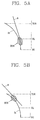
- the position with which the electron beam 6 collides differs depending on the deflection angle as designed in the CRT. If the deflection angle is small, as shown in Figure 5A, the electron beam collides with the neck seal line 23 of the inner surface 31 of the yoke portion. Meanwhile, if the deflection angle is large, as shown in Figure 5B, the electron beam collides with the inner surface 31 of the yoke portion at the side of the top of round 21.
- the BSN phenomenon occurs according to the margin between the inner surface 31 of the yoke portion 2b and the electron beam passing region. If there is no margin, as shown in Figure 6, a shadow is formed at the end 25 of the effective surface diagonal portion due to the BSN phenomenon.
- the yoke portion 2b of the funnel 2 should be designed to be small so that it can come as close as possible to the electron beam 6. But in the aspect of implementation of an image without the BSN phenomenon, there is a limitation in designing to make the yoke portion 2b small.
- an object of the present invention is to provide a method for designing an optimum funnel yoke portion that is capable of reducing a deflection power in fabricating a slim type CRT and capable of obtaining a margin between an inner side of a funnel and an electron beam passing region without causing a BSN phenomenon.
- a funnel structure of a cathode ray tube having a panel with a fluorescent screen inside thereof, a funnel sealed to the panel in a vacuum state, an electron gun mounted at a neck portion of the funnel and emitting an electron beam toward the fluorescent screen, and a deflection yoke mounted at a yoke portion of the funnel and deflecting the electron beam, wherein provided that a deflection angle is 110° or more, a length of an outer surface evaluation line formed by connecting a TOR outer surface end where the funnel yoke portion and the funnel body portion meet and a neck seal outer surface end where the funnel yoke portion and the neck portion meet by a straight line is 'a' and a length of a straight line from the outer surface evaluation line where a vertical distance between the funnel yoke portion outer surface and the outer surface evaluation line is maximized, to the neck seal outer surface end is 'b'
- a funnel structure of a cathode ray tube having a panel with a fluorescent screen inside thereof, a funnel sealed to the panel in a vacuum state, an electron gun mounted at a neck portion of the funnel and emitting an electron beam toward the fluorescent screen, and a deflection yoke mounted at a yoke portion of the funnel and deflecting the electron beam, wherein provided that a deflection angle is 110° or more, a length of an outer surface evaluation line formed by connecting a TOR outer surface end where the funnel yoke portion and the funnel body portion meet and a neck seal outer surface end where the funnel yoke portion and the neck portion meet by a straight line is 'a', a length of a straight line from the outer surface evaluation line where a vertical distance between the funnel yoke portion outer surface and the outer surface evaluation line is maximized, to the neck seal outer surface end is 'b', a length of a straight line from a point on an outer surface of the funnel
- a funnel structure of a cathode ray tube having a panel with a fluorescent screen inside thereof, a funnel sealed to the panel in a vacuum state, an electron gun mounted at a neck portion of the funnel and emitting an electron beam toward the fluorescent screen, and a deflection yoke mounted at a yoke portion of the funnel and deflecting the electron beam, wherein provided that a deflection angle is 110° or more, a length of an inner surface evaluation line formed by connecting a TOR inner surface end where the funnel yoke portion and the funnel body portion meet and a neck seal inner surface end where the funnel yoke portion and the neck portion meet by a straight line is 'a", a length of a straight line from the inner surface evaluation line where a vertical distance between the funnel yoke portion inner surface and the inner surface evaluation line is maximized, to the neck seal inner surface end is 'b", a formula of 0.20 ⁇ b'/a' ⁇ 0.40 is satisfied,
- a funnel structure of a cathode ray tube having a panel with a fluorescent screen inside thereof, a funnel sealed to the panel in a vacuum state, an electron gun mounted at a neck portion of the funnel and emitting an electron beam toward the fluorescent screen, and a deflection yoke mounted at a yoke portion of the funnel and deflecting the electron beam, wherein provided that a deflection angle is 110° or more, a length of an inner surface evaluation line formed by connecting a TOR inner surface end where the funnel yoke portion and the funnel body portion meet and a neck seal inner surface end where the funnel yoke portion and the neck portion meet by a straight line is 'a", a length of a straight line from the inner surface evaluation line where a vertical distance between the funnel yoke portion inner surface and the inner surface evaluation line is maximized, to the neck seal inner surface end is 'b", a length of a straight line from a point on an inner surface of the funnel yok
- the present invention is directed to an optimum shape design of a funnel yoke portion, allowing a BSN margin so as to restrain a BSN phenomenon caused when an electron beam is deflected at an inner surface of a funnel while maintaining optimum deflection power, in case that CRT is made slim.
- the optimization of the funnel structure of the CRT starts from that a straight line connecting an end of an outer surface 32 of a top of round 21 where a funnel yoke portion 2b and a funnel body portion 2a meet and an end of an outer surface 32 of a neck seal line 23 where the funnel yoke portion 2b and a neck portion 2c meet is defined as an outer surface evaluation line (OL), a length of the outer surface evaluation line (OL) is defined as 'a', and a distance on the outer surface evaluation line (OL) from the end of the neck seal line 23 to a point where the distance can be the maximum is 'b' when a straight line is drawn to the outer surface evaluation line (OL) from an arbitrary one point of an outer surface 32 of the funnel 2.
- OL outer surface evaluation line
- the conventional CRTs have the b/a ratio of above 0.41 by models.
- the ratio between 'a' and 'b', the lengths of the outer surface evaluation lines (OL) of the funnel yoke portion 2b for the wide angle product is designed to satisfy the below formula so that a BSN margin can be obtained and deflection power can be reduced. 0.20 ⁇ b/a ⁇ 0.40
- Figure 11 is a graph showing a BSN margin according to the b/a value, the length ratio of the outer surface evaluation line (OL) of the funnel yoke portion 2b of the wide angle production with a deflection angle of 110° or more. It is noted that in case of applying the funnel yoke portion 2b designed in the ratio of above 0.41 as in the conventional art to the wide angle product with the deflection angle of 110° or more, the BSN margin is absolutely insufficient.
- the position of the deflection yoke 5 is moved to be corrected in the direction of the tube axis 24, so as to adjust an optimal value.
- the length ratio b/a of the outer surface evaluation line (OL) of the funnel yoke portion 2b satisfies the following formula: 0.20 ⁇ b/a ⁇ 0.35
- a straight line connecting an end of an outer surface 32 of a top of round 21 where a funnel yoke portion 2b and a funnel body portion 2a meet and an end of an outer surface 32 of a neck seal line 23 where funnel yoke portion 2b and a neck portion 2c meet is defined as an outer surface evaluation line (OL)
- a length of the outer surface evaluation line (OL) is defined as 'a'
- a distance on the outer surface evaluation line (OL) from the end of the neck seal line 23 to a point where the distance can be the maximum is 'b' when a straight line is drawn to the outer surface evaluation line (OL) from an arbitrary one point of an outer surface 32 of the funnel 2
- a straight line from a point on the outer surface 32 of the funnel yoke portion 2b where a vertical distance from the outer surface 32 of the funnel yoke portion 2b to the outer surface evaluation line (OL) is maximized to the end of the neck seal line 23 is 'b1'
- a ratio of d/c can be determined, which becomes a reference to evaluate the shape of the funnel yoke portion 2b as to whether the BSN margin is obtained or not when the deflection angle is a wide angle.
- the CRT has the optimum BSN margin. 0.22 ⁇ d/c ⁇ 0.42
- Table 2 shows the deflection power level of a wide angle product according to d/c ratios for the optimum BSN margin. As shown in below Table 2, if the d/c ratio is above 0.22, the deflection power is also reduced. Deflection power ⁇ ⁇ ⁇ o ⁇ d/c ratio 0.12 0.22 0.32 0.42 o ⁇ : Very Good ⁇ : Good ⁇ : Common ⁇ : Bad
- the inner surface 31 of the funnel yoke portion 2b should be taken into consideration in its design by applying the concept of the present invention.
- the inner and outer surface the funnel 2 of the conventional CRT has such a shape that the thickness is increased as it goes from the neck seal line 23 to the funnel body portion 2a in order to smoothly connect the thickness of the funnel body portion 2a and the funnel yoke portion 2b.
- the shapes are almost the same, with little difference value, the ratio of b/a and d/c of the outer surface 32 of the funnel yoke portion 2b of the present invention were obtained the same as that of an experiment result on the inner surface 31 of the funnel yoke portion of the conventional art.
- the experiment value at the outer surface 32 of the funnel yoke portion 2b can be adoptable to the inner surface 31 of the funnel yoke portion 2b.
- a straight line connecting an end of an inner surface 31 of a top of round 21 where a funnel yoke portion 2b and a funnel body portion 2a meet and an end of an inner surface 31 of a neck seal line 23 where funnel yoke portion 2b and a neck portion 2c meet is defined as an inner surface evaluation line (IL)
- a length of the inner surface evaluation line (IL) is defined as 'a"
- a distance on the inner surface evaluation line (IL) from the end of the neck seal line 23 to a point where the distance can be the maximum is 'b" when a straight line is drawn to the inner surface evaluation line (IL) from an arbitrary one point of the outer surface 32 of the funnel 2
- the CRT should satisfy the following formula (4): 0.20 ⁇ b'/a' ⁇ 0.40
- a straight line connecting an end of an inner surface 31 of a top of round 21 where a funnel yoke portion 2b and a funnel body portion 2a meet and an end of an inner surface 31 of a neck seal line 23 where funnel yoke portion 2b and a neck portion 2c meet is defined as an inner surface evaluation line (IL)
- a length of the inner surface evaluation line (IL) is defined as 'a"
- a distance on the inner surface evaluation line (IL) from the end of the neck seal line 23 to a point where the distance can be the maximum is 'b" when a straight line is drawn to the inner surface evaluation line (IL) from an arbitrary one point of the inner surface 31 of the funnel 2
- a straight line from a point on the inner surface 31 of the funnel yoke portion 2b where a vertical distance from the inner surface 31 of the funnel yoke portion 2b to the outer surface evaluation line (OL) is maximized to the end of the neck seal line 23 is 'b1", the angle between 'b
- the funnel structure of the CRT of the present invention has the following advantages.
- the CRT designed according to the above optimum conditions would reduce a power applied for lots of deflection accompanying in fabricating a slim type CRT.
- occurrence of a shadow at the corner portions of the panel can be prevented.
Landscapes
- Vessels, Lead-In Wires, Accessory Apparatuses For Cathode-Ray Tubes (AREA)
Applications Claiming Priority (2)
| Application Number | Priority Date | Filing Date | Title |
|---|---|---|---|
| KR2002025931 | 2002-05-10 | ||
| KR10-2002-0025931A KR100447662B1 (ko) | 2002-05-10 | 2002-05-10 | 음극선관 |
Publications (2)
| Publication Number | Publication Date |
|---|---|
| EP1361598A2 true EP1361598A2 (de) | 2003-11-12 |
| EP1361598A3 EP1361598A3 (de) | 2005-05-18 |
Family
ID=29244832
Family Applications (1)
| Application Number | Title | Priority Date | Filing Date |
|---|---|---|---|
| EP02027239A Withdrawn EP1361598A3 (de) | 2002-05-10 | 2002-12-06 | Trichterstruktur einer Kathodenstrahlröhre |
Country Status (5)
| Country | Link |
|---|---|
| US (1) | US6777866B2 (de) |
| EP (1) | EP1361598A3 (de) |
| JP (1) | JP2003331756A (de) |
| KR (1) | KR100447662B1 (de) |
| CN (1) | CN1236472C (de) |
Families Citing this family (2)
| Publication number | Priority date | Publication date | Assignee | Title |
|---|---|---|---|---|
| ITMI20041929A1 (it) * | 2004-10-12 | 2005-01-12 | Videocolor Spa | Involucro in vetro per tubo a raggi catodici |
| KR20060035151A (ko) * | 2004-10-21 | 2006-04-26 | 엘지.필립스 디스플레이 주식회사 | 음극선관 |
Family Cites Families (9)
| Publication number | Priority date | Publication date | Assignee | Title |
|---|---|---|---|---|
| JP3405675B2 (ja) * | 1998-03-16 | 2003-05-12 | 株式会社東芝 | 陰極線管装置 |
| KR100334015B1 (ko) * | 1998-11-10 | 2002-09-26 | 삼성에스디아이 주식회사 | 음극선관 |
| KR100300320B1 (ko) * | 1998-11-16 | 2001-11-30 | 김순택 | 음극선관_ |
| KR100605761B1 (ko) * | 1999-04-14 | 2006-07-31 | 엘지전자 주식회사 | 음극선관 |
| KR100667592B1 (ko) * | 1999-05-10 | 2007-01-12 | 엘지전자 주식회사 | 음극선관 |
| KR100318376B1 (ko) * | 1999-06-01 | 2001-12-22 | 김순택 | 음극선관 |
| KR100589396B1 (ko) * | 1999-06-07 | 2006-06-13 | 삼성에스디아이 주식회사 | 음극선관 |
| KR100551044B1 (ko) * | 1999-07-05 | 2006-02-09 | 삼성에스디아이 주식회사 | 음극선관 |
| KR100589397B1 (ko) * | 1999-06-25 | 2006-06-13 | 삼성에스디아이 주식회사 | 음극선관 |
-
2002
- 2002-05-10 KR KR10-2002-0025931A patent/KR100447662B1/ko not_active Expired - Fee Related
- 2002-12-06 EP EP02027239A patent/EP1361598A3/de not_active Withdrawn
- 2002-12-11 US US10/315,988 patent/US6777866B2/en not_active Expired - Fee Related
- 2002-12-31 CN CNB021517169A patent/CN1236472C/zh not_active Expired - Fee Related
-
2003
- 2003-01-29 JP JP2003020710A patent/JP2003331756A/ja active Pending
Also Published As
| Publication number | Publication date |
|---|---|
| CN1457079A (zh) | 2003-11-19 |
| US20030209969A1 (en) | 2003-11-13 |
| JP2003331756A (ja) | 2003-11-21 |
| US6777866B2 (en) | 2004-08-17 |
| KR20030087849A (ko) | 2003-11-15 |
| KR100447662B1 (ko) | 2004-09-07 |
| CN1236472C (zh) | 2006-01-11 |
| EP1361598A3 (de) | 2005-05-18 |
Similar Documents
| Publication | Publication Date | Title |
|---|---|---|
| CA1159874A (en) | Deflection yoke comprising magnetically permeable members forming a pincushion shape field within the neck of a crt | |
| KR100443611B1 (ko) | 음극선관용 패널 | |
| US6777866B2 (en) | Funnel structure of cathode ray tube | |
| KR100489604B1 (ko) | 평면 칼라 음극선관 | |
| EP1310977A2 (de) | Schattenmaske für Farbkathodenstrahlröhre | |
| US7154215B2 (en) | Color cathode ray tube capable of reducing stress | |
| KR100502465B1 (ko) | 상하주사형 음극선관 | |
| US7291964B2 (en) | Color cathode ray tube | |
| KR100605761B1 (ko) | 음극선관 | |
| US7355331B2 (en) | Cathode-ray tube apparatus | |
| US7183703B2 (en) | Cathode ray tube and manufacturing method of deflection coil | |
| KR100510903B1 (ko) | 칼라음극선관용 펀넬 | |
| KR100493513B1 (ko) | 평면 음극선관 | |
| KR100426013B1 (ko) | 칼라 음극선관 | |
| KR20010069127A (ko) | 평면 브라운관의 새도우마스크 도밍 방지구조 | |
| KR100414495B1 (ko) | 상하주사형 음극선관 | |
| KR100414484B1 (ko) | 평면 브라운관의 프레임 구조 | |
| KR100468427B1 (ko) | 칼라 음극선관 | |
| KR20040006520A (ko) | 음극선관용 편향 요크 | |
| KR100489606B1 (ko) | 음극선관 | |
| US20030227244A1 (en) | Cathode ray tube | |
| US20030222563A1 (en) | Structure of slot feature for shadow mask | |
| KR20020018424A (ko) | 편향요크의 버티컬 센터 라스터 보정편 | |
| JPH07182987A (ja) | カラー受像管 | |
| KR20020092738A (ko) | 음극선관 |
Legal Events
| Date | Code | Title | Description |
|---|---|---|---|
| PUAI | Public reference made under article 153(3) epc to a published international application that has entered the european phase |
Free format text: ORIGINAL CODE: 0009012 |
|
| AK | Designated contracting states |
Kind code of ref document: A2 Designated state(s): AT BE BG CH CY CZ DE DK EE ES FI FR GB GR IE IT LI LU MC NL PT SE SI SK TR |
|
| AX | Request for extension of the european patent |
Extension state: AL LT LV MK RO |
|
| PUAL | Search report despatched |
Free format text: ORIGINAL CODE: 0009013 |
|
| AK | Designated contracting states |
Kind code of ref document: A3 Designated state(s): AT BE BG CH CY CZ DE DK EE ES FI FR GB GR IE IT LI LU MC NL PT SE SI SK TR |
|
| AX | Request for extension of the european patent |
Extension state: AL LT LV MK RO |
|
| 17P | Request for examination filed |
Effective date: 20051021 |
|
| AKX | Designation fees paid |
Designated state(s): DE FR GB NL |
|
| STAA | Information on the status of an ep patent application or granted ep patent |
Free format text: STATUS: THE APPLICATION HAS BEEN WITHDRAWN |
|
| 18W | Application withdrawn |
Effective date: 20060616 |