EP1361460A2 - Tripelreflektor und diesen enthaltendes Weitwinkelsensorsystem - Google Patents
Tripelreflektor und diesen enthaltendes Weitwinkelsensorsystem Download PDFInfo
- Publication number
- EP1361460A2 EP1361460A2 EP03007645A EP03007645A EP1361460A2 EP 1361460 A2 EP1361460 A2 EP 1361460A2 EP 03007645 A EP03007645 A EP 03007645A EP 03007645 A EP03007645 A EP 03007645A EP 1361460 A2 EP1361460 A2 EP 1361460A2
- Authority
- EP
- European Patent Office
- Prior art keywords
- triple
- reflector
- wide
- light
- angle
- Prior art date
- Legal status (The legal status is an assumption and is not a legal conclusion. Google has not performed a legal analysis and makes no representation as to the accuracy of the status listed.)
- Granted
Links
- 239000011521 glass Substances 0.000 claims description 4
- 239000004033 plastic Substances 0.000 claims description 4
- 229920003023 plastic Polymers 0.000 claims description 4
- 229920003229 poly(methyl methacrylate) Polymers 0.000 claims description 3
- 239000004926 polymethyl methacrylate Substances 0.000 claims description 3
- PXHVJJICTQNCMI-UHFFFAOYSA-N Nickel Chemical compound [Ni] PXHVJJICTQNCMI-UHFFFAOYSA-N 0.000 claims 4
- 229910052751 metal Inorganic materials 0.000 claims 3
- 239000002184 metal Substances 0.000 claims 3
- 229910001369 Brass Inorganic materials 0.000 claims 2
- 229910000906 Bronze Inorganic materials 0.000 claims 2
- RYGMFSIKBFXOCR-UHFFFAOYSA-N Copper Chemical compound [Cu] RYGMFSIKBFXOCR-UHFFFAOYSA-N 0.000 claims 2
- BQCADISMDOOEFD-UHFFFAOYSA-N Silver Chemical compound [Ag] BQCADISMDOOEFD-UHFFFAOYSA-N 0.000 claims 2
- 229910000831 Steel Inorganic materials 0.000 claims 2
- RTAQQCXQSZGOHL-UHFFFAOYSA-N Titanium Chemical compound [Ti] RTAQQCXQSZGOHL-UHFFFAOYSA-N 0.000 claims 2
- 229910052782 aluminium Inorganic materials 0.000 claims 2
- XAGFODPZIPBFFR-UHFFFAOYSA-N aluminium Chemical compound [Al] XAGFODPZIPBFFR-UHFFFAOYSA-N 0.000 claims 2
- 239000010951 brass Substances 0.000 claims 2
- 239000010974 bronze Substances 0.000 claims 2
- 229910052802 copper Inorganic materials 0.000 claims 2
- 239000010949 copper Substances 0.000 claims 2
- KUNSUQLRTQLHQQ-UHFFFAOYSA-N copper tin Chemical compound [Cu].[Sn] KUNSUQLRTQLHQQ-UHFFFAOYSA-N 0.000 claims 2
- PCHJSUWPFVWCPO-UHFFFAOYSA-N gold Chemical compound [Au] PCHJSUWPFVWCPO-UHFFFAOYSA-N 0.000 claims 2
- 229910052737 gold Inorganic materials 0.000 claims 2
- 239000010931 gold Substances 0.000 claims 2
- 239000011133 lead Substances 0.000 claims 2
- 229910052759 nickel Inorganic materials 0.000 claims 2
- MOFOBJHOKRNACT-UHFFFAOYSA-N nickel silver Chemical compound [Ni].[Ag] MOFOBJHOKRNACT-UHFFFAOYSA-N 0.000 claims 2
- 239000010956 nickel silver Substances 0.000 claims 2
- 229910052709 silver Inorganic materials 0.000 claims 2
- 239000004332 silver Substances 0.000 claims 2
- 239000010959 steel Substances 0.000 claims 2
- 239000010936 titanium Substances 0.000 claims 2
- 229910052719 titanium Inorganic materials 0.000 claims 2
- VYPSYNLAJGMNEJ-UHFFFAOYSA-N Silicium dioxide Chemical compound O=[Si]=O VYPSYNLAJGMNEJ-UHFFFAOYSA-N 0.000 claims 1
- 230000005540 biological transmission Effects 0.000 claims 1
- 239000005388 borosilicate glass Substances 0.000 claims 1
- 239000005329 float glass Substances 0.000 claims 1
- 239000005304 optical glass Substances 0.000 claims 1
- 239000004417 polycarbonate Substances 0.000 claims 1
- 229920000515 polycarbonate Polymers 0.000 claims 1
- 239000004800 polyvinyl chloride Substances 0.000 claims 1
- 238000007493 shaping process Methods 0.000 claims 1
- 238000004544 sputter deposition Methods 0.000 claims 1
- 238000007740 vapor deposition Methods 0.000 claims 1
- 238000004519 manufacturing process Methods 0.000 description 15
- 238000005286 illumination Methods 0.000 description 13
- 230000011514 reflex Effects 0.000 description 13
- 238000005516 engineering process Methods 0.000 description 11
- 238000000034 method Methods 0.000 description 10
- 238000012360 testing method Methods 0.000 description 6
- 238000010276 construction Methods 0.000 description 5
- 238000013461 design Methods 0.000 description 5
- 230000010287 polarization Effects 0.000 description 5
- 230000000694 effects Effects 0.000 description 4
- 238000005259 measurement Methods 0.000 description 4
- 238000000465 moulding Methods 0.000 description 3
- 238000003491 array Methods 0.000 description 2
- 239000011888 foil Substances 0.000 description 2
- 239000000463 material Substances 0.000 description 2
- 230000003287 optical effect Effects 0.000 description 2
- 230000015572 biosynthetic process Effects 0.000 description 1
- 238000012937 correction Methods 0.000 description 1
- 230000007423 decrease Effects 0.000 description 1
- 238000009826 distribution Methods 0.000 description 1
- 238000005304 joining Methods 0.000 description 1
- 238000003754 machining Methods 0.000 description 1
- 238000000691 measurement method Methods 0.000 description 1
- 238000012986 modification Methods 0.000 description 1
- 230000004048 modification Effects 0.000 description 1
- 238000005375 photometry Methods 0.000 description 1
- 238000012545 processing Methods 0.000 description 1
- 230000001953 sensory effect Effects 0.000 description 1
Images





Classifications
-
- B—PERFORMING OPERATIONS; TRANSPORTING
- B29—WORKING OF PLASTICS; WORKING OF SUBSTANCES IN A PLASTIC STATE IN GENERAL
- B29D—PRODUCING PARTICULAR ARTICLES FROM PLASTICS OR FROM SUBSTANCES IN A PLASTIC STATE
- B29D11/00—Producing optical elements, e.g. lenses or prisms
- B29D11/00605—Production of reflex reflectors
-
- G—PHYSICS
- G02—OPTICS
- G02B—OPTICAL ELEMENTS, SYSTEMS OR APPARATUS
- G02B5/00—Optical elements other than lenses
- G02B5/12—Reflex reflectors
- G02B5/122—Reflex reflectors cube corner, trihedral or triple reflector type
-
- G—PHYSICS
- G02—OPTICS
- G02B—OPTICAL ELEMENTS, SYSTEMS OR APPARATUS
- G02B5/00—Optical elements other than lenses
- G02B5/12—Reflex reflectors
- G02B5/122—Reflex reflectors cube corner, trihedral or triple reflector type
- G02B5/124—Reflex reflectors cube corner, trihedral or triple reflector type plural reflecting elements forming part of a unitary plate or sheet
Definitions
- the invention relates to a method and the formation of a suitable Reflector for wide-angle observation of a reflective surface using a Reflex sensor, which may also be equipped with polarization filters or can work as a laser reflex sensor.
- the wide-angle sensor system with triple reflector consists of one teaching to choose the observation angle and a triple reflector that is made up of a large number of triples.
- the one around the triple center arranged triple partial surfaces namely mirror sides, almost on the right Angle to each other and the axis of the triple alternately by -5 ° and + 5 ° or more deviates from the incidence of the reflector surface.
- a special feature of the triple is the considerable lengthening at least one triple surface.
- the aim of the wide-angle sensor system with triple reflector is to To create reflex sensor system with which an area can be observed can with an opening angle of 80 ° and more at a Retroreflective value at each angle of illumination of the observed horizontal area of at least 3,000 mcd / Ix.
- the problem is that so far there have been none for the tasks of reflex sensors high-quality reflective surfaces on the market that a deliver an intense retroflex signal consistently, especially not when the reflecting surface is positioned differently from the plumb at 40 ° and more.
- the reflectors or reflective foils on the market as far as they are have wide-angle properties, are designed for road traffic, for reflective signs or personal protection reflectors on clothes. These reflective structures create a broadband distribution of the reflected light. As a result, their reflected light energy is insufficient from giving reflex sensors bundled reliable retroflex signals. Most of the light must be available for reflex sensors are retro-reflected to the recipient.
- the main purpose of the polarization filter system is that of the sensor emitted light and then via the retroflector in its polarity distinguish rotated and reflected light from extraneous light or reflections that can emanate from other bodies in the room.
- the wide-angle system according to the invention with its triple reflector special design enables the operation of the sensor with Polarizing filter system.
- this novel triple reflector can also be designed using known technology as a micro cube reflector, as is required in particular for laser sensors or film technology.
- the requirements for laser sensor technology are described by the inventor in DE 197 27 527 . Because pyramidal triple surfaces are completely unsuitable for the aim of the present invention, on the one hand because they retroflect only about 66 ° of the light, and on the other hand because they are unsuitable for the required light beam contour and precision for laser sensors.
- the invention therefore uses a special design of full-cube triples.
- a full cube triple consists of three square mirrors that are at right angles to each other and retroflect the light to the light source.
- Stimson tools are described which suggest the production of the cube-shaped, reflecting surfaces by using single ground pins or notched plates.
- the reflector described in the present invention and the Production of the tools is based on the known methods for Manufacture of triple reflectors, but choose a new shape, the comes close to the Fullcube.
- the invention makes use of the experience gained in the manufacture and use of full-cube triples in technology.
- the full-cube triple has the excellent property of receiving incident light within a wide tolerance range of the angle of incidence and retroflecting it almost completely to the light source.
- the retroflexion takes place via the reflection of light on the three square surfaces of the full-cube triple.
- This angle tolerance for the incident light is used in practical use with most retro-reflective sensors today.
- the assembly and alignment of the reflectors at an angle to the transmitter / receiver system is simple and fault-tolerant. Beam movements due to vibrations are usually tolerated by this reflection element with full-cube triples.
- the manufacture of the reflector technology knows Fullcube-Triple, their Triple axis deviating from the incidence of the reflector surface is aligned.
- This enlarged, elongated triple partial area helps a lot to catch light falling at wide angles and to the rest Pass triple subareas so that the light towards Light source is retroflected.
- a triple is created that is completely Surprisingly, in practice, it works much more widely than you do could expect.
- Manufacturing methods are selected for the reflector according to the invention that create a special triple surface, the character of which clearly distinguishes from reflex surfaces, which are formed by pins were.
- the triple partial surfaces are approximately the same size, square, so are in the special variation of the full-cube triple, as in the invention Reflector is used, at least one triple partial surface per triple is significantly larger than the smallest triple partial area of the triple.
- the triple axes of the triple are aligned in the reflector according to the invention in a manner very different from the incidence perpendicular to the reflector surface, namely at least +/- 5 ° and more and combined with triples whose triple axes, for example +/- 15 ° from Incidence slot of the reflector surface deviate.
- the desired extended triple partial surface is created when the notch Tool element plates when using the Stimson plate method by the oblique wedge-shaped incision in the plates (Fig. 11 and 12).
- a triple partial surface which is also long but almost unlimited in width, is obtained when using the plate method as described by Gubela in DE 44 10 994 C2 , for example in FIGS. 13 and 14 there.
- the triple axes are aligned by 5 ° deviating from the incidence of the reflector surface very advantageous for that Wide-angle sensor system according to the invention. You get at Representation of the reflector with this method additionally one Wide angle not only in the horizontal, but also in the Vertical.
- the invention proposes a wide-angle sensor with a reflector, at which a light receiver is used for a light transmitter so that the observation angle is as small as possible.
- the observation angle of 0 ° means that the light receiver is positioned in relation to the light transmitter that the retroreflected light from the reflector is on the same axis is received as it was sent.
- Such arrangements are in the Sensors are known and are, for example, by using semi-transparent mirrors or beam splitters solved. However, comes with this arrangement lost some light energy because it is also undesirable Beam paths arise.
- the light receiver as close as possible to the axis of the Position light transmitter so that an observation angle of greater than 0 °, for example 0.2 °, and no more than 1 °. Then can the reflector is observed over a horizontal of approximately + 40 ° to -40 ° be what an opening angle of the area observed by the sensor corresponds to about 80 ° and a continuous retroreflective power of Reflector of over 3,000 mcd / lx.
- By changing the triple axes some triple in the reflector up to about +/- 15 ° and more Opening angle can be expanded significantly. Because with the tipping the triple axis away from the incidence of the reflector surface, i.e.
- the lengthened also increases Partial triple surface that captures the light much better.
- the amazing Effect of the system according to the invention is based on this particular Triple shape of the reflector, the wide angle of the reflector is not achieved only by pivoting the triple axis, but by associated enlargement of the extended triple partial area. So is achieved by pivoting the triple axes horizontally +/- 5 ° already a horizontal wide-angle of more than 40 °, remains but the extremely high reflective power of over 9,000 mcd / Ix at horizontal and vertical 0 °.
- the invention thus enables a wide-angle sensor system To create triple reflector through an observation angle of Wide angle sensor of 1 ° or smaller and the design of a Triple arrays for the reflector, which consists of a variety of full-cube triples of which the majority of triples are at least one have much longer triple partial area and their triple axis Is inclined +/- 5 ° or more with respect to the incidence of the light entry surface, and when using a manufacturing method of the full-cube triple Stimson plates or Gubela strands, so that one Illumination angle of +/- 40 ° or more of the wide-angle sensor his entire observation angle of 80 ° or more Retroflex signal, whose retroreflective value never falls below 3,000 mcd / lx decreases and so the wide-angle sensor also with a polarization filter can be equipped.
- the reflector on the Light entrance surface can be equipped with a Fresnel lens that the Illumination range increased.
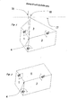
- Fig. 1 shows a single triple of the wide-angle mirror structure of the reflector, according to claim 1.
- the triple consists of three mirror surfaces (1, 2, 3) which are almost at right angles to each other, namely between 89 ° and 91 °.
- the slight deviations of 90 ° are due to the different refractive properties for processing coming plastics or glasses and the different Shrinkage behavior of the materials required in tool making leading angle correction.
- the shape of the mirror surface (3) is striking Is square.
- This shape is created in an inventive Wide-angle structure of the reflector when the structure is horizontal should be wide-angled on both sides, i.e. the angle of inclination Triple axes to the incidence of the reflector surface for one Group of triples should be + 5 ° and for the second triple group -5 ° should be. It should be noted that you can of course use other triples other angles of inclination of the triple axes of the wide-angle structure can add, for example with a tilt angle of 0 ° or about +/- 15 °.
- An essential feature of the triple is that the two triple partial surfaces, the mirror surfaces (2 and 3), are significantly larger and longer than the triple partial surface 1.
- at least one triple partial surface is to be significantly extended in the direction of the light to be received from a wide-angle position ,
- the elongated triple partial surface (2) according to the invention thus achieves the illumination wide angle in FIG. 3 horizontally, the triple partial surface (3) in a substantially smaller vertical direction. See also the table in FIG. 33.
- the center of the triple is the lowest point (4) that all three mirror surfaces touch.
- the base of the triple projected onto a plane is an uneven hexagon.
- the shape of the cube corner is such that it may communicate with other similar cube corners to a wide-angle mirror structure of the reflector (Fig. 3 and Fig. 4) are assembled that can capture the incident light of two opposing directions.
- the light entrance surface (17) of the reflector is not positioned to scale here.
- the incident perpendicular (16) to the light entry surface (17) corresponds to a direct angle of incidence of the light at 0 ° horizontally and vertically.
- the triple axis (18) of the triple points away to the right by approximately -5 ° from the perpendicular, inclined to the triple partial surface (2).
- the slope could also be towards the edge of the triple be performed, which is formed by the triple partial surfaces (2 and 3). It is important for the present invention that the inclination of the Triple axis in the direction of the extended triple partial surface or partial surfaces towards, or to the triple edge, which extended from these Partial areas is formed. Because this is the invention Light trapping effect of the extended triple surfaces for the Wide-angle range effective.
- Fig . 2 a single triple of the wide-angle mirror structure of the reflector, said triplet included in a segment, see Fig. 20 and Fig. 21, the wide-angle mirror structure that is oriented to one side only at a wide angle out for being illuminated, as shown in Figs. 7 to 10 shown.
- This triple consists of three mirror surfaces (1, 2, 5), which in turn are almost at right angles to each other.
- its triple axis is inclined by -5 ° to the right toward the triple surface 2.
- the shape of the triple partial surfaces, mirror surfaces (2 and 5), are each elongated rectangles.
- the center of the triple is the lowest point (4).
- the base of the triple projected onto a plane is an uneven hexagon.
- the shape of the cube corner is so designed that it can be assembled with other similar cube corners to a wide-angle mirror structure of the reflector (Fig. 7 and Fig. 8), the incident light predominantly from one direction in space is located to the right of the axis of incidence and retroflexed.
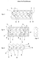
- Fig. 3 is a wide-angle mirror structure of the reflector, which is assembled from triplets of Fig. 1. Due to the perspective view, the mirror surfaces (2 and 7) of FIG. 4 are not visible.
- the mirror surfaces (1) and (3) show the triples of the first orientation.
- the mirror surfaces (6) and (8) show the triples of the second orientation in their position rotated by 180 ° compared to the triples of the first orientation.
- the triples of the same orientation are arranged in rows. Rows with opposite directions alternate.
- the orientation of the triple roughly determines the spatial direction from which it preferably receives light.
- the angle of inclination of the triple axis is referred to indicated with minus if the inclination in the figure for shows the viewer to the right and is given a plus if the Inclination to the left in the figure.
- Fig. 4 shows the wide-angle mirror structure of the reflector of Fig. 3 in the view from above and thus the projection of all edges onto a base.
- Fig. 5 is a section through the wide-angle mirror structure of the reflector of Fig. 4. The section goes through the opposing Tripel-2n.
- Fig. 6 rotated the wide-angle mirror structure of the reflector in space so that all mirror surfaces (3) of the triple of the first orientation (9) with the mirror surfaces (8) of the triple of the second orientation (10) show a closed reflecting surface for the viewer. It is clear here that the wide-angle mirror structure of the reflector can be seamlessly assembled from the triples of FIG. 1.
- Fig. 7 shows the wide-angle mirror structure of the reflector, which is aligned on one side to the right and which is assembled from triplets of Fig. 2. Due to the perspective view, one mirror surface (12) of FIG. 8 is not visible.
- Fig. 8 shows the same wide-angle mirror structure of the reflector of Fig. 7 in the view from above and thus the projection of all edges onto a base. All mirror surfaces of the triples are rectangles. The mirror surfaces (11, 12, 13) are arranged around the triple center (14). All triples are evenly aligned and therefore receive the light predominantly from the right side of the slot.
- Fig. 9 shows the section through the wide-angle mirror structure of the reflector of FIG. 8. The section goes through all arranged in the same orientation triplet.
- Fig. 10 rotated the wide-angle mirror structure of the reflector of Fig. 7 in space so that all mirror surfaces (13) of the triple of the same orientation (15) show a closed surface for the viewer like a single large mirror.
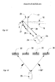
- Fig. 11 shows the principle of the triple with the extended triple partial surface (2).
- the two other triple partial surfaces face this at an almost right angle, shown in this two-dimensional sketch as line (23).
- the triple axis (18) deviates from the incident perpendicular (16) of the light entry surface (17) by, for example, 5 °.
- the triple axis is inclined towards the extended triple partial surface (2).
- the light transmitter (24) of the reflex sensor sends the light beam (26), which still finds reference points within the triple on the extended triple partial surface (2), which enables the light to be retroflected via the beam path (28) to the receiver (25). Even if the transmitter and receiver are exchanged in this example, the beam path results in the opposite direction.
- the sensor (29) capable of deviating observe the reflectors also upon rotation of more than +/- 40 ° from the optical path between the sensor and the reflector.
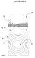
- Fig. 16 in a vertical section the reflector (30) on the light entry side (17) was additionally structured on the surface with a Fresnel lens.
- the Fresnel lens reinforces the ability of the reflector to be wide-angled.
- the theoretical lens shape (31) has an arc flattened in the center and determines the shape of the Fresnel structure applied linearly in circles in this example.
- the Fresnel structure can be micronized using known technology in a machining process.
- Fig. 17 the reflector (30) of Fig. 16 in view of the light entry surface (17) with the linear circles of the Fresnel structure (32) and the flat center (33) of the surface of the light entry side (17), which was not structured.
- the Fresnel lens can also have a completely different shape for special sensory tasks.
- the reflector can also be curved in itself or only that Light entering side.
- Fig. 18 the reflector (30), in the view from the light entry surface, with a division of the reflex structure into the segments (35) and (36).
- the wide-angledness could be produced by rotating the second segment 90 ° to one another, pointing horizontally and vertically to all four sides of the reflector.
- this figure shows that one-sided structures of FIG. 7 are arranged next to one another rotated by 180 °, so that the structural surface (34) is effective to the left (37) and the structural surface (35) is effective to the right (36) is.
- the arrows show the direction in which the extended triple partial surfaces point.
- the reflector (30) in the view from the light entry surface, divided into numerous segments that point in very different directions with the extended triple partial surfaces, for example (38) and (39). However, segments can also be added whose triples are not inclined, so that their triple axis corresponds to the perpendicular to the reflector surface.
- Fig. 20 to Fig. 31 show the tool production to produce the wide-angle acting reflectors with the aid of Gubela plate method.
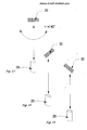
- Fig. 20 is a tool element (40), which is designed as a glass body and can also be a reflector element itself, with a chamfer that forms an almost unlimited triple partial surface (41).
- the plate-shaped tool element is notched on the upper edge. The edges of the notches form the two further triple partial surfaces (42) and (43) visible in FIG. 25.
- Fig. 21 shows the tool element from the broad side with the chamfer (41).
- Fig. 22 the tool element of the narrow side with the angle (44) which determines the location of the notch. If the triple axis is to be inclined to the large triple partial surface (41) by, for example, 5 °, an angle of approximately 30 ° would be used here in relation to the light entry surface of the reflector.
- Fig. 23 shows the strand-like tool element in a view perpendicularly from the light entrance surface.
- the triple partial surface extending over the entire length of the strand is opposite the triple partial surfaces (42) and (43). All triple partial surfaces are at almost right angles to each other.
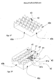
- Fig. 24 is a full reflector structure assembled from the four tool elements (40).
- FIG. 25 corresponds to FIG. 24 viewed from the light incidence slot.
- the triple partial surface (41) enlarged in length and in width and the triple partial surfaces (42) and (43).
- Fig. 26 the block of the four tool elements in section.
- FIG. 27 shows the negative of FIG. 24, which corresponds to the galvanic impression and can be used as a metallic reflector or as a tool structure for the molding of wide-angle reflectors.
- the triple partial surfaces (42) and (43) are marked.
- the triple partial surface (41) cannot be seen.
- the outer edges of the negative are identified by (40a) and (40b) and the hidden outer edge (40c), so that the rotation of the negative in relation to the viewer can be seen in the following FIG. 28.
- Fig. 28 the rotated toward the viewer negative in FIG. 27 with the outer edge (40b) and the now exposed outer edges (40c).
- the lengthened triple partial surfaces (41) according to the invention run in their width over the entire length of the negative.
- the triple partial surfaces (42) and (43) are almost at right angles to the triple partial surface (41).
- the part (41a) visible in this illustration and the part (41b) which is not visible are shown on the actually effective triple partial surface (41) which bears reference points suitable for the two marked triple partial surfaces (42) and (43) in order to provide light from a wide angle of illumination capture.
- the design with the Gubela strands enables wide-angle triples belonging to the group of full-cube triplets with a very large light trapping area for wide-angle light.
- the large triple partial surface (41) can simultaneously provide overlapping reference surfaces, which are formed from the sum of all reference points and which can capture light and can transmit this to the other triple partial surfaces for retroflexion.
- Fig. 29 to Fig. 31 yet another variation of the Gubela show strands to frame additional light trapping extended for a second spatial direction, for example vertical.
- Fig. 29 the tool element (45) which is similar to the tool element (40) of Fig. 22. However, the notches (46) that meet the chamfer (47) are formed with non-uniform sides, which is visible in Fig. (30).
- Fig. 30 the tool element in longitudinal section with the indicated chamfer (47) and the non-shaped notches (46).
- the edges (48) and (49) of the notches (46) form the two triple partial surfaces, which are almost at right angles to the chamfer (47), which corresponds to the third triple partial surface .
- Fig. 31 the view of the tool element from the light entry side to the incoming perpendicular corresponding.
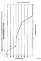
- FIG. 32 shows the retroreflection values of an exemplary reflector made of PMMA, which corresponds to the retroflective structure of FIG. 3, as a function of the angle of illumination in the horizontal axis of FIG. 4 at an observation angle of 0.2 °.
- the measurement method The vertical angle is 0 °.
- the Xoffset is 0 ° and the Yoffset is 0.5 °.
- the horizontal angles are entered on the x-axis and the reflectance values in mcd / lx on the y-axis.
- the test sample "IMOS Wide Angle 1" was commissioned by the company IMOS Gubela GmbH, Renchen, Germany, for the inventor and consists of a 50x50 mm reflector plate with a welded back box.
- the reflecting surface is approximately 47 ⁇ 47 mm in size and consists of the structures according to the invention from FIG. 3 with significantly extended triple partial surfaces, the maximum power of which is somewhat horizontal.
- the reflex structure consists of triples, which are set in tracks and whose extended triple side is rotated by 180 ° per track. The inclination of the triple axes is 5 ° inclined towards the extended triple surfaces.
- the triples are designed as microcube triples, the smallest edge length of which is approximately 1 mm.
- the triple structure is suitable for sensors with polarization filters or laser sensors.
- the construction of the structure of the test specimen is like all in this invention proposed designs of the triple arrays also for the production micro-structured reflective foils.
- FIG. 33 shows the table of the photometric measurement results in detail from FIG. 32. It means (test point), the indication of the observation angle 0.2 ° followed by the illumination angles in degrees with horizontal (H) and vertical (V). (HV) is the angle of illumination at 0 ° horizontally and vertically. It can be seen that the test sample was designed for horizontal wide-angle.
Landscapes
- Physics & Mathematics (AREA)
- Engineering & Computer Science (AREA)
- Optics & Photonics (AREA)
- General Physics & Mathematics (AREA)
- Ophthalmology & Optometry (AREA)
- Mechanical Engineering (AREA)
- Health & Medical Sciences (AREA)
- Manufacturing & Machinery (AREA)
- Optical Elements Other Than Lenses (AREA)
- Length Measuring Devices By Optical Means (AREA)
- Photometry And Measurement Of Optical Pulse Characteristics (AREA)
- Optical Radar Systems And Details Thereof (AREA)
- Aerials With Secondary Devices (AREA)
- Navigation (AREA)
- Measurement Of Velocity Or Position Using Acoustic Or Ultrasonic Waves (AREA)
Abstract
Description
Die Messmethode: Der Vertikalwinkel ist 0°. Um die Spiegelung auf der Lichteintrittsfläche des Reflektors auszublenden betragen der Xoffset 0°, der Yoffset 0,5°. Auf der x-Achse sind die Horizontalwinkel, auf der Y-Achse die Rückstrahlwerte in mcd/lx eingetragen. Das Prüfmuster "IMOS Weitwinkel 1" ist von der Firma IMOS Gubela GmbH, Renchen, Deutschland, für den Erfinder auftragsgefertigt und besteht aus einer 50x50 mm großen Reflektorplatte mit aufgeschweißtem Rückkasten. Die Reflexfläche ist etwa 47x47 mm groß und besteht aus den erfindungsgemäßen Strukturen der Fig. 3 mit deutlich verlängerten Tripelteilflächen, deren Leistungsmaximum etwas aus der Horizontalen liegt. Die Reflexstruktur besteht aus Tripeln, die in Spuren gesetzt sind und deren verlängerte Tripelseite je Spur um 180° gedreht ist. Die Neigung der Tripelachsen betragen 5° jeweils zu den verlängerten Tripelflächen hin geneigt. Die Tripel sind als Mikrocubetripel ausgebildet, deren kleinste Kantenlänge etwa 1 mm beträgt. Die Tripelstruktur ist für Sensoren mit Polarisationsfilter oder Lasersensoren geeignet.
Man erkennt, dass das Prüfmuster auf die horizontale Weitwinkligkeit hin gestaltet wurde.
Claims (20)
- Reflektor mit einer Vielzahl von Tripeln, wobei die Tripel jeweils aus drei Tripelteilflächen (1, 2, 3) bestehen, die zueinander in einem Winkel von 89° bis 91° angeordnet sind, wobei mindestens eine Tripelteilfläche von über 50 % der Tripel nicht quadratisch ist und größer ist als die übrigen Tripelteilflächen, und wobei die Tripelachse (18) dieser Tripel um mindestens 5° vom Einfallslot (16) der Reflektoroberfläche (17) in einer Richtung hin zu der größeren Tripelteilfläche abweicht.
- Reflektor nach Anspruch 1, dadurch gekennzeichnet, dass jeweils zwei Tripelteilflächen von über 50 % der Tripel nicht quadratisch sind und größer sind als die übrige Tripelteilfläche und dass die Tripelachse (18) dieser Tripel um mindestens 5° vom Einfallslot (16) der Reflektoroberfläche (17) in einer Richtung hin zu den größeren Tripelteilflächen abweicht.
- Reflektor nach Anspruch 1 oder 2, dadurch gekennzeichnet, dass die Tripelteilflächen (1, 2, 3) Spiegelflächen sind.
- Reflektor nach einem der vorangehenden Ansprüche, dadurch gekennzeichnet, dass die Tripel in Reihen angeordnet sind, und dass die Tripel zueinander benachbarter Reihen Abweichungen der Tripelachse (18) vom Einfallslot (16) in entgegengesetzte Richtungen aufweisen.
- Reflektor nach einem der vorangehenden Ansprüche, dadurch gekennzeichnet, dass die die Tripel formenden Werkzeugelemente (40) strangförmige Platten sind, die auf ihrer Kante Einkerbungen besitzen, die mindestens zwei Tripelteilflächen formen können.
- Reflektor nach einem der vorangehenden Ansprüche, dadurch gekennzeichnet, dass mindestens ein Teil seiner Lichteintrittsoberfläche (17) als Fresnel-Linse ausgebildet ist.
- Reflektor nach Anspruch 6, dadurch gekennzeichnet, dass seine gesamte Lichteintrittsoberfläche (17) als Fresnel-Linse ausgebildet ist.
- Reflektor nach einem der vorangehenden Ansprüche, dadurch gekennzeichnet, dass er als optischer Glaskörper ausgebildet ist, gefertigt aus Glas, vorzugsweise Floatglas, Borosilikatglas oder Quarzglas.
- Reflektor nach einem der Ansprüche 1 bis 7, dadurch gekennzeichnet, dass er aus lichtdurchlässigem Kunststoff ausgebildet ist, vorzugsweise aus Polymethylmethacrylat (PMMA), Polyvinylchlorid (PVC) oder Polycarbonat (PC).
- Reflektor nach einem der vorangehenden Ansprüche, dadurch gekennzeichnet, dass er als Hartteil ausgebildet ist.
- Reflektor nach einem der Ansprüche 1 bis 9, dadurch gekennzeichnet, dass er als Prägeteil ausgebildet ist.
- Reflektor nach einem der Ansprüche 1 bis 9, dadurch gekennzeichnet, dass er als elastische Folie ausgebildet ist.
- Reflektor nach einem der vorangehenden Ansprüche, dadurch gekennzeichnet, dass die Tripel aus Metall ausgebildet sind, vorzugsweise aus Gold, Silber, Aluminium, Nickel, Messing, Kupfer, Bronze, Neusilber, Titan, Blei oder Stahl.
- Reflektor nach einem der Ansprüche 1 bis 12, dadurch gekennzeichnet, dass die Tripel eine auf einen formgebenden Trägerkörper aufgebrachte Metallfläche, vorzugsweise aus Gold, Silber, Aluminium, Nickel, Messing, Kupfer, Bronze, Neusilber, Titan, Blei oder Stahl, aufweisen.
- Reflektor nach Anspruch 14, dadurch gekennzeichnet, dass die Metallfläche durch Bedampfen oder Sputtern aufgebracht ist.
- Weitwinkelsensorsystem, gekennzeichnet durch einen Reflektor nach einem der Ansprüche 1 bis 15.
- Weitwinkelsensorsystem nach Anspruch 16, gekennzeichnet durch einen Lichtsender (24) und einen Lichtempfänger (25).
- Weitwinkelsensorsystem nach Anspruch 17, dadurch gekennzeichnet, dass der Lichtempfänger (25) mit dem Lichtsender (24) einen Beobachtungswinkel von maximal 1° einschließt.
- Weitwinkelsensorsystem nach Anspruch 18, dadurch gekennzeichnet, dass der Lichtempfänger (25) so bezüglich des Lichtsenders (24) angeordnet ist, dass er reflektiertes Licht auf der gleichen Achse empfängt, auf der es vom Lichtsender (24) gesendet wurde.
- Weitwinkelsensorsystem nach einem der Ansprüche 16 bis 19, dadurch gekennzeichnet, dass der Sendestrahl des Weitwinkelsensors so groß in seiner Form gewählt wird, dass er mindestens zwei Tripel des Reflektors berührt.
Priority Applications (2)
| Application Number | Priority Date | Filing Date | Title |
|---|---|---|---|
| EP08164500A EP1998192A3 (de) | 2002-04-14 | 2003-04-03 | Tripelreflektor mit Fresnel-Linse und diesen enthaltendes Weitwinkelsensorsystem |
| EP08164497A EP2012147A3 (de) | 2002-04-14 | 2003-04-03 | Tripelreflektor und diesen enthaltendes Weitwinkelsensorsystem |
Applications Claiming Priority (2)
| Application Number | Priority Date | Filing Date | Title |
|---|---|---|---|
| DE10216579 | 2002-04-14 | ||
| DE10216579A DE10216579A1 (de) | 2002-04-14 | 2002-04-14 | Weitwinkelsensorsystem mit Tripelreflektor und Herstellung der Werkzeuge |
Related Child Applications (2)
| Application Number | Title | Priority Date | Filing Date |
|---|---|---|---|
| EP08164500A Division EP1998192A3 (de) | 2002-04-14 | 2003-04-03 | Tripelreflektor mit Fresnel-Linse und diesen enthaltendes Weitwinkelsensorsystem |
| EP08164497A Division EP2012147A3 (de) | 2002-04-14 | 2003-04-03 | Tripelreflektor und diesen enthaltendes Weitwinkelsensorsystem |
Publications (3)
| Publication Number | Publication Date |
|---|---|
| EP1361460A2 true EP1361460A2 (de) | 2003-11-12 |
| EP1361460A3 EP1361460A3 (de) | 2005-01-05 |
| EP1361460B1 EP1361460B1 (de) | 2009-01-21 |
Family
ID=28458830
Family Applications (3)
| Application Number | Title | Priority Date | Filing Date |
|---|---|---|---|
| EP03007645A Expired - Lifetime EP1361460B1 (de) | 2002-04-14 | 2003-04-03 | Tripelreflektor und diesen enthaltendes Weitwinkelsensorsystem |
| EP08164500A Withdrawn EP1998192A3 (de) | 2002-04-14 | 2003-04-03 | Tripelreflektor mit Fresnel-Linse und diesen enthaltendes Weitwinkelsensorsystem |
| EP08164497A Withdrawn EP2012147A3 (de) | 2002-04-14 | 2003-04-03 | Tripelreflektor und diesen enthaltendes Weitwinkelsensorsystem |
Family Applications After (2)
| Application Number | Title | Priority Date | Filing Date |
|---|---|---|---|
| EP08164500A Withdrawn EP1998192A3 (de) | 2002-04-14 | 2003-04-03 | Tripelreflektor mit Fresnel-Linse und diesen enthaltendes Weitwinkelsensorsystem |
| EP08164497A Withdrawn EP2012147A3 (de) | 2002-04-14 | 2003-04-03 | Tripelreflektor und diesen enthaltendes Weitwinkelsensorsystem |
Country Status (4)
| Country | Link |
|---|---|
| US (3) | US7135671B2 (de) |
| EP (3) | EP1361460B1 (de) |
| AT (1) | ATE421706T1 (de) |
| DE (2) | DE10216579A1 (de) |
Cited By (3)
| Publication number | Priority date | Publication date | Assignee | Title |
|---|---|---|---|---|
| CN104148898A (zh) * | 2014-08-08 | 2014-11-19 | 浙江道明光电科技有限公司 | 具有微棱镜阵列结构的反光材料模具的制作方法 |
| EP2442148B1 (de) | 2003-03-06 | 2016-06-08 | 3M Innovative Properties Co. | Schicht mit würfeleckförmigen Elementen und retroreflektive Folie |
| CN111830777A (zh) * | 2014-05-27 | 2020-10-27 | 米拉维兹公司 | 用于优化逆反射显示系统的方法 |
Families Citing this family (22)
| Publication number | Priority date | Publication date | Assignee | Title |
|---|---|---|---|---|
| US7152983B2 (en) | 2003-03-06 | 2006-12-26 | 3M Innovative Properties Company | Lamina comprising cube corner elements and retroreflective sheeting |
| US7308207B2 (en) * | 2003-11-17 | 2007-12-11 | Raytheon Company | Method for identifying an interrogated object using a dynamic optical tag identification system |
| ZA200802679B (en) * | 2005-09-26 | 2009-08-26 | Avery Dennison Corp | Retroreflective sheeting comprising a divergence enhancing layer |
| DE202006013375U1 (de) † | 2006-08-31 | 2006-11-02 | Sick Ag | Ziel für eine optoelektronische Schutzeinrichtung |
| US8465639B2 (en) * | 2008-04-09 | 2013-06-18 | Orafol Americas Inc. | Pin based method of precision diamond turning to make prismatic mold and sheeting |
| CN102246067B (zh) * | 2008-12-08 | 2014-07-16 | 日本电石工业株式会社 | 回射物品 |
| US9295741B2 (en) * | 2012-03-27 | 2016-03-29 | Earl Yerby | Apparatus and method for sanitizing articles utilizing a plurality of reflector units to evenly distribute UV radiation |
| JP2016080937A (ja) * | 2014-10-20 | 2016-05-16 | 株式会社アスカネット | 再帰性反射体製造用の金型及びこの金型を用いた再帰性反射体の製造方法 |
| RU2707211C2 (ru) * | 2014-11-20 | 2019-11-25 | Авери Деннисон Корпорейшн | Световозвращатель из плиток, изготовленный способом многоэтапной нарезки кубиками |
| DE102016118656B4 (de) | 2016-09-30 | 2022-10-20 | Automotive Lighting Reutlingen Gmbh | Fahrzeug mit einem Retroreflektor mit mehreren Retroreflektorelementen |
| CN110300904A (zh) | 2017-02-20 | 2019-10-01 | 3M创新有限公司 | 包括延迟片的回射制品 |
| EP3582642A4 (de) | 2017-02-20 | 2021-01-13 | 3M Innovative Properties Company | Optische artikel und damit interagierende systeme |
| EP3583449A4 (de) | 2017-02-20 | 2020-12-30 | 3M Innovative Properties Company | Retroreflektierender gegenstand mit kontrastverringerungsschicht |
| WO2019064108A1 (en) | 2017-09-27 | 2019-04-04 | 3M Innovative Properties Company | PERSONAL PROTECTIVE EQUIPMENT MANAGEMENT SYSTEM USING OPTICAL PATTERNS FOR EQUIPMENT AND SECURITY MONITORING |
| DE102018101289B4 (de) | 2018-01-22 | 2019-10-17 | Imos Gubela Gmbh | Retroreflektor mit einer gekrümmten Oberfläche, Abformwerkzeug zur Herstellung des Retroreflektors und Verfahren zur Herstellung des Abformwerkzeugs |
| DE102018101291B4 (de) | 2018-01-22 | 2020-10-29 | Hans-Erich Gubela | Verwendung und Verfahren zur Herstellung eines elastischen Retroreflektors |
| DE102018101292B4 (de) | 2018-01-22 | 2020-10-29 | Hans-Erich Gubela | Retroreflektorelement zur Verwendung im Straßenverkehr und Spritzgussform |
| DE102018112043B4 (de) * | 2018-05-18 | 2022-01-13 | Hans-Erich Gubela | Anordnung eines Retroreflektors mit Optikelementen |
| DE102018117569B4 (de) | 2018-07-20 | 2023-09-07 | Hans-Erich Gubela | Retroreflektor, Spritzgussform und Verwendung eines Retroreflektors |
| CN109765537B (zh) * | 2019-01-04 | 2020-10-13 | 北京环境特性研究所 | 一种极化可调节的角反射器和角反射器极化调节方法 |
| DE102020004967B4 (de) * | 2020-08-14 | 2024-08-01 | Hans-Erich Gubela | Retroreflektierendes Element mit einem Sicherheitselement |
| DE102021111397B4 (de) | 2021-05-03 | 2026-01-08 | Endress+Hauser Sick Gmbh+Co. Kg | Reflektor für ein Transmissiometer und damit ausgerüstetes Transmissiometer |
Family Cites Families (28)
| Publication number | Priority date | Publication date | Assignee | Title |
|---|---|---|---|---|
| GB269760A (en) | 1926-07-02 | 1927-04-28 | Jonathan Cass Stimson | Process and apparatus for making central triple reflectors |
| US3649153A (en) * | 1969-11-04 | 1972-03-14 | Peter E Brudy | Faceted core |
| US3899154A (en) * | 1970-09-05 | 1975-08-12 | Ichikoh Industries Ltd | Light reflector mold |
| US3923378A (en) * | 1973-04-24 | 1975-12-02 | Amerace Corp | Cube-corner reflector with non-aligned cube axes and element axes |
| US3833285A (en) * | 1973-05-22 | 1974-09-03 | Amerace Esna Corp | Retrodirective reflector visible over wide range of observation angles |
| USRE29396E (en) * | 1975-02-18 | 1977-09-13 | Amerace Corporation | Pin having nonaligned cube axis and pin axis and bundle of such pins |
| US4066236A (en) * | 1976-06-25 | 1978-01-03 | Beatrice Foods Co. | Cube corner type retroreflector bodies and molds made therewith |
| US4095773A (en) * | 1976-11-18 | 1978-06-20 | Beatrice Foods Co. | Subassemblies for cube corner type retroreflector molds |
| US4189209A (en) * | 1978-10-13 | 1980-02-19 | Ferro Corporation | Retroreflector of integrated light reflecting units of varying configurations |
| US4588258A (en) * | 1983-09-12 | 1986-05-13 | Minnesota Mining And Manufacturing Company | Cube-corner retroreflective articles having wide angularity in multiple viewing planes |
| DE4410994C2 (de) * | 1992-10-30 | 1996-01-25 | Gubela Sen Hans Erich | Körper oder Bauteil eines strangförmigen Tripelreflektors und Werkzeugelement zur Abformung von Tripelreflektoren |
| WO1994018581A1 (de) * | 1993-01-30 | 1994-08-18 | Kernforschungszentrum Karlsruhe Gmbh | Abformwerkzeug, verfahren zu dessen herstellung und tripelspiegel |
| DK111293D0 (da) * | 1993-10-04 | 1993-10-04 | Franke Kell Erik | Retroreflektivt foliemateriale |
| US5565151A (en) * | 1994-09-28 | 1996-10-15 | Reflexite Corporation | Retroreflective prism structure with windows formed thereon |
| JP3359456B2 (ja) * | 1995-01-31 | 2002-12-24 | 日本カーバイド工業株式会社 | 内部全反射型再帰反射シート |
| CN1106252C (zh) * | 1995-07-28 | 2003-04-23 | 日本电石工业株式会社 | 微棱镜母型 |
| US6010609A (en) * | 1995-07-28 | 2000-01-04 | Nippon Carside Kogyo Kabushiki Kaisha | Method of making a microprism master mold |
| US6159407A (en) * | 1996-01-26 | 2000-12-12 | 3M Innovative Properties Company | Stacked laminate mold and method of making |
| US6015214A (en) * | 1996-05-30 | 2000-01-18 | Stimsonite Corporation | Retroreflective articles having microcubes, and tools and methods for forming microcubes |
| DE29707066U1 (de) * | 1997-04-21 | 1997-08-14 | IMOS Gubela GmbH, 77871 Renchen | Mikroretroflektor |
| DE19727527C5 (de) * | 1997-06-30 | 2015-02-19 | Hans-Erich Gubela sen. | Auf der Retroreflexion eines Laserstrahlers basierende Sensoreinrichtung |
| EP1017557B1 (de) * | 1997-07-02 | 2004-12-08 | Minnesota Mining And Manufacturing Company | Form für würfeleckenbahnen und verfahren zu deren herstellung |
| US5981032A (en) * | 1997-07-02 | 1999-11-09 | 3M Innovative Properties Company | Retroreflective cube corner sheeting mold and sheeting formed therefrom |
| AU1662801A (en) * | 1999-11-23 | 2001-06-04 | Digilens Inc. | Optical retro-reflection device |
| JP3468418B2 (ja) * | 2000-03-15 | 2003-11-17 | 日本カーバイド工業株式会社 | 三角錐型キユーブコーナー型再帰反射シート |
| US6353489B1 (en) * | 2000-11-23 | 2002-03-05 | Digilens, Inc. | Optical retro-reflection device |
| US6626544B2 (en) * | 2001-03-28 | 2003-09-30 | Reflexite Corporation | Prismatic retroreflector having a multi-plane facet |
| DE10119671A1 (de) * | 2001-04-20 | 2002-10-24 | Sen Hans-Erich Gubela | Umlenkspiegelstruktur, bestehend aus einer Vielzahl von Tripeln |
-
2002
- 2002-04-14 DE DE10216579A patent/DE10216579A1/de not_active Ceased
-
2003
- 2003-04-03 DE DE50311110T patent/DE50311110D1/de not_active Expired - Lifetime
- 2003-04-03 EP EP03007645A patent/EP1361460B1/de not_active Expired - Lifetime
- 2003-04-03 EP EP08164500A patent/EP1998192A3/de not_active Withdrawn
- 2003-04-03 AT AT03007645T patent/ATE421706T1/de not_active IP Right Cessation
- 2003-04-03 EP EP08164497A patent/EP2012147A3/de not_active Withdrawn
- 2003-04-14 US US10/412,936 patent/US7135671B2/en not_active Expired - Lifetime
-
2006
- 2006-08-14 US US11/503,750 patent/US7268340B2/en not_active Expired - Lifetime
-
2007
- 2007-05-30 US US11/807,845 patent/US20070258157A1/en not_active Abandoned
Cited By (3)
| Publication number | Priority date | Publication date | Assignee | Title |
|---|---|---|---|---|
| EP2442148B1 (de) | 2003-03-06 | 2016-06-08 | 3M Innovative Properties Co. | Schicht mit würfeleckförmigen Elementen und retroreflektive Folie |
| CN111830777A (zh) * | 2014-05-27 | 2020-10-27 | 米拉维兹公司 | 用于优化逆反射显示系统的方法 |
| CN104148898A (zh) * | 2014-08-08 | 2014-11-19 | 浙江道明光电科技有限公司 | 具有微棱镜阵列结构的反光材料模具的制作方法 |
Also Published As
| Publication number | Publication date |
|---|---|
| DE50311110D1 (de) | 2009-03-12 |
| US7268340B2 (en) | 2007-09-11 |
| EP1361460B1 (de) | 2009-01-21 |
| US20070007441A1 (en) | 2007-01-11 |
| ATE421706T1 (de) | 2009-02-15 |
| US20030193717A1 (en) | 2003-10-16 |
| EP2012147A3 (de) | 2009-04-29 |
| EP2012147A2 (de) | 2009-01-07 |
| US20070258157A1 (en) | 2007-11-08 |
| EP1361460A3 (de) | 2005-01-05 |
| US7135671B2 (en) | 2006-11-14 |
| DE10216579A1 (de) | 2003-10-23 |
| EP1998192A3 (de) | 2009-04-29 |
| EP1998192A2 (de) | 2008-12-03 |
Similar Documents
| Publication | Publication Date | Title |
|---|---|---|
| EP1361460B1 (de) | Tripelreflektor und diesen enthaltendes Weitwinkelsensorsystem | |
| DE69429113T2 (de) | Zur verwendung in der verglasung geeignetes optisches bauelement | |
| DE3624188C2 (de) | ||
| DE3688123T2 (de) | Flexibler duenner film mit totaler interner reflexion. | |
| DE69222765T2 (de) | Optischer spiegel | |
| DE3689417T2 (de) | Lichtablenkungsvorrichtung. | |
| DE69504496T2 (de) | Optische vorrichtung mit gerichteter reflexion | |
| EP3688367A1 (de) | Kraftfahrzeugbeleuchtungsvorrichtung mit unterteilte mikro-eintrittsoptiken aufweisenden mikrooptik-systemen | |
| DE69932853T2 (de) | Abbildende artikel und zweiachsige retroreflektierende elemente verwendende verfahren | |
| DE4236799A1 (de) | Verfahren zur Herstellung von Tripel-Reflektoren und deren Werkzeugen | |
| DE4429683C1 (de) | Körper oder Bauteil eines strangförmigen Tripelreflektors und/ oder Werkzeugelements zur Abformung von Tripelreflektoren | |
| EP1251367B1 (de) | Umlenkspiegelstruktur, bestehend aus einer Vielzahl von Tripeln | |
| DE102008055857B4 (de) | Effiziente Lichtumlenkvorrichtung mit zweiseitiger prismatischer und linsenartiger Oberflächenstrukturierung | |
| DE202008015402U1 (de) | Optische Lichtstreueinheit | |
| DE102012022418B4 (de) | Retroreflektor, optisches System, ortsfeste Anordnung eines Retroreflektors und Abformwerkzeug | |
| EP3523572B1 (de) | Lichtumlenkvorrichtung, verfahren zur herstellung einer lichtumlenkvorrichtung und beleuchtungsvorrichtung | |
| EP1894043B1 (de) | Licht reflektierendes tripel, reflektor sowie verfahren zur erkennung eines gegenstands | |
| DE10324402A1 (de) | Optische Vorrichtung mit vielen Gruppierungen Eindimensionaler optischer Elemente | |
| DE102016001543A1 (de) | Retro-Rückstrahler | |
| DE19622670C2 (de) | Lichtumlenkplatte mit zwei flächig ausgebildeten Elementen | |
| DE112020001104T5 (de) | Verfahren zur herstellung einer lichtleiterplatte, eine lichterleitplatte und eine beleuchtungseinrichtung für fahrzeuge | |
| DE3842199A1 (de) | Refraktor mit veraenderbarem brechungsverhalten | |
| DE102018101289B4 (de) | Retroreflektor mit einer gekrümmten Oberfläche, Abformwerkzeug zur Herstellung des Retroreflektors und Verfahren zur Herstellung des Abformwerkzeugs | |
| DE678176C (de) | Rueckstrahler fuer Nah- und Fernlicht | |
| DE2552267C3 (de) | Rückblickspiegel für Straßenfahrzeuge, insbesondere Kraftfahrzeuge |
Legal Events
| Date | Code | Title | Description |
|---|---|---|---|
| PUAI | Public reference made under article 153(3) epc to a published international application that has entered the european phase |
Free format text: ORIGINAL CODE: 0009012 |
|
| AK | Designated contracting states |
Kind code of ref document: A2 Designated state(s): AT BE BG CH CY CZ DE DK EE ES FI FR GB GR HU IE IT LI LU MC NL PT RO SE SI SK TR |
|
| AX | Request for extension of the european patent |
Extension state: AL LT LV MK |
|
| PUAL | Search report despatched |
Free format text: ORIGINAL CODE: 0009013 |
|
| AK | Designated contracting states |
Kind code of ref document: A3 Designated state(s): AT BE BG CH CY CZ DE DK EE ES FI FR GB GR HU IE IT LI LU MC NL PT RO SE SI SK TR |
|
| AX | Request for extension of the european patent |
Extension state: AL LT LV MK |
|
| RIC1 | Information provided on ipc code assigned before grant |
Ipc: 7G 02B 5/12 A Ipc: 7B 23Q 16/00 B Ipc: 7G 02B 5/124 B Ipc: 7B 29D 11/00 B |
|
| 17P | Request for examination filed |
Effective date: 20050324 |
|
| AKX | Designation fees paid |
Designated state(s): AT BE BG CH CY CZ DE DK EE ES FI FR GB GR HU IE IT LI LU MC NL PT RO SE SI SK TR |
|
| GRAP | Despatch of communication of intention to grant a patent |
Free format text: ORIGINAL CODE: EPIDOSNIGR1 |
|
| GRAS | Grant fee paid |
Free format text: ORIGINAL CODE: EPIDOSNIGR3 |
|
| GRAS | Grant fee paid |
Free format text: ORIGINAL CODE: EPIDOSNIGR3 |
|
| GRAA | (expected) grant |
Free format text: ORIGINAL CODE: 0009210 |
|
| AK | Designated contracting states |
Kind code of ref document: B1 Designated state(s): AT BE BG CH CY CZ DE DK EE ES FI FR GB GR HU IE IT LI LU MC NL PT RO SE SI SK TR |
|
| REG | Reference to a national code |
Ref country code: GB Ref legal event code: FG4D Free format text: NOT ENGLISH |
|
| REG | Reference to a national code |
Ref country code: CH Ref legal event code: EP |
|
| REG | Reference to a national code |
Ref country code: IE Ref legal event code: FG4D Free format text: LANGUAGE OF EP DOCUMENT: GERMAN |
|
| REF | Corresponds to: |
Ref document number: 50311110 Country of ref document: DE Date of ref document: 20090312 Kind code of ref document: P |
|
| PG25 | Lapsed in a contracting state [announced via postgrant information from national office to epo] |
Ref country code: NL Free format text: LAPSE BECAUSE OF FAILURE TO SUBMIT A TRANSLATION OF THE DESCRIPTION OR TO PAY THE FEE WITHIN THE PRESCRIBED TIME-LIMIT Effective date: 20090121 |
|
| NLV1 | Nl: lapsed or annulled due to failure to fulfill the requirements of art. 29p and 29m of the patents act | ||
| PG25 | Lapsed in a contracting state [announced via postgrant information from national office to epo] |
Ref country code: SI Free format text: LAPSE BECAUSE OF FAILURE TO SUBMIT A TRANSLATION OF THE DESCRIPTION OR TO PAY THE FEE WITHIN THE PRESCRIBED TIME-LIMIT Effective date: 20090121 Ref country code: FI Free format text: LAPSE BECAUSE OF FAILURE TO SUBMIT A TRANSLATION OF THE DESCRIPTION OR TO PAY THE FEE WITHIN THE PRESCRIBED TIME-LIMIT Effective date: 20090121 Ref country code: ES Free format text: LAPSE BECAUSE OF FAILURE TO SUBMIT A TRANSLATION OF THE DESCRIPTION OR TO PAY THE FEE WITHIN THE PRESCRIBED TIME-LIMIT Effective date: 20090502 |
|
| REG | Reference to a national code |
Ref country code: IE Ref legal event code: FD4D |
|
| PG25 | Lapsed in a contracting state [announced via postgrant information from national office to epo] |
Ref country code: PT Free format text: LAPSE BECAUSE OF FAILURE TO SUBMIT A TRANSLATION OF THE DESCRIPTION OR TO PAY THE FEE WITHIN THE PRESCRIBED TIME-LIMIT Effective date: 20090622 Ref country code: SE Free format text: LAPSE BECAUSE OF FAILURE TO SUBMIT A TRANSLATION OF THE DESCRIPTION OR TO PAY THE FEE WITHIN THE PRESCRIBED TIME-LIMIT Effective date: 20090421 |
|
| PG25 | Lapsed in a contracting state [announced via postgrant information from national office to epo] |
Ref country code: IE Free format text: LAPSE BECAUSE OF FAILURE TO SUBMIT A TRANSLATION OF THE DESCRIPTION OR TO PAY THE FEE WITHIN THE PRESCRIBED TIME-LIMIT Effective date: 20090121 Ref country code: EE Free format text: LAPSE BECAUSE OF FAILURE TO SUBMIT A TRANSLATION OF THE DESCRIPTION OR TO PAY THE FEE WITHIN THE PRESCRIBED TIME-LIMIT Effective date: 20090121 Ref country code: DK Free format text: LAPSE BECAUSE OF FAILURE TO SUBMIT A TRANSLATION OF THE DESCRIPTION OR TO PAY THE FEE WITHIN THE PRESCRIBED TIME-LIMIT Effective date: 20090121 Ref country code: CZ Free format text: LAPSE BECAUSE OF FAILURE TO SUBMIT A TRANSLATION OF THE DESCRIPTION OR TO PAY THE FEE WITHIN THE PRESCRIBED TIME-LIMIT Effective date: 20090121 |
|
| BERE | Be: lapsed |
Owner name: GUBELA, HANS-ERICH, SR. Effective date: 20090430 |
|
| PLBE | No opposition filed within time limit |
Free format text: ORIGINAL CODE: 0009261 |
|
| STAA | Information on the status of an ep patent application or granted ep patent |
Free format text: STATUS: NO OPPOSITION FILED WITHIN TIME LIMIT |
|
| PG25 | Lapsed in a contracting state [announced via postgrant information from national office to epo] |
Ref country code: RO Free format text: LAPSE BECAUSE OF FAILURE TO SUBMIT A TRANSLATION OF THE DESCRIPTION OR TO PAY THE FEE WITHIN THE PRESCRIBED TIME-LIMIT Effective date: 20090121 Ref country code: SK Free format text: LAPSE BECAUSE OF FAILURE TO SUBMIT A TRANSLATION OF THE DESCRIPTION OR TO PAY THE FEE WITHIN THE PRESCRIBED TIME-LIMIT Effective date: 20090121 |
|
| REG | Reference to a national code |
Ref country code: CH Ref legal event code: PL |
|
| GBPC | Gb: european patent ceased through non-payment of renewal fee |
Effective date: 20090421 |
|
| 26N | No opposition filed |
Effective date: 20091022 |
|
| REG | Reference to a national code |
Ref country code: FR Ref legal event code: ST Effective date: 20091231 |
|
| PG25 | Lapsed in a contracting state [announced via postgrant information from national office to epo] |
Ref country code: LI Free format text: LAPSE BECAUSE OF NON-PAYMENT OF DUE FEES Effective date: 20090430 Ref country code: CH Free format text: LAPSE BECAUSE OF NON-PAYMENT OF DUE FEES Effective date: 20090430 Ref country code: BG Free format text: LAPSE BECAUSE OF FAILURE TO SUBMIT A TRANSLATION OF THE DESCRIPTION OR TO PAY THE FEE WITHIN THE PRESCRIBED TIME-LIMIT Effective date: 20090421 |
|
| PG25 | Lapsed in a contracting state [announced via postgrant information from national office to epo] |
Ref country code: MC Free format text: LAPSE BECAUSE OF NON-PAYMENT OF DUE FEES Effective date: 20090430 Ref country code: GB Free format text: LAPSE BECAUSE OF NON-PAYMENT OF DUE FEES Effective date: 20090421 Ref country code: FR Free format text: LAPSE BECAUSE OF NON-PAYMENT OF DUE FEES Effective date: 20091222 |
|
| PG25 | Lapsed in a contracting state [announced via postgrant information from national office to epo] |
Ref country code: BE Free format text: LAPSE BECAUSE OF NON-PAYMENT OF DUE FEES Effective date: 20090430 |
|
| PG25 | Lapsed in a contracting state [announced via postgrant information from national office to epo] |
Ref country code: AT Free format text: LAPSE BECAUSE OF NON-PAYMENT OF DUE FEES Effective date: 20090403 |
|
| PGFP | Annual fee paid to national office [announced via postgrant information from national office to epo] |
Ref country code: DE Payment date: 20100424 Year of fee payment: 8 |
|
| PG25 | Lapsed in a contracting state [announced via postgrant information from national office to epo] |
Ref country code: GR Free format text: LAPSE BECAUSE OF FAILURE TO SUBMIT A TRANSLATION OF THE DESCRIPTION OR TO PAY THE FEE WITHIN THE PRESCRIBED TIME-LIMIT Effective date: 20090422 |
|
| PG25 | Lapsed in a contracting state [announced via postgrant information from national office to epo] |
Ref country code: IT Free format text: LAPSE BECAUSE OF FAILURE TO SUBMIT A TRANSLATION OF THE DESCRIPTION OR TO PAY THE FEE WITHIN THE PRESCRIBED TIME-LIMIT Effective date: 20090121 |
|
| PG25 | Lapsed in a contracting state [announced via postgrant information from national office to epo] |
Ref country code: LU Free format text: LAPSE BECAUSE OF NON-PAYMENT OF DUE FEES Effective date: 20090403 |
|
| PG25 | Lapsed in a contracting state [announced via postgrant information from national office to epo] |
Ref country code: HU Free format text: LAPSE BECAUSE OF FAILURE TO SUBMIT A TRANSLATION OF THE DESCRIPTION OR TO PAY THE FEE WITHIN THE PRESCRIBED TIME-LIMIT Effective date: 20090722 |
|
| PG25 | Lapsed in a contracting state [announced via postgrant information from national office to epo] |
Ref country code: TR Free format text: LAPSE BECAUSE OF FAILURE TO SUBMIT A TRANSLATION OF THE DESCRIPTION OR TO PAY THE FEE WITHIN THE PRESCRIBED TIME-LIMIT Effective date: 20090121 |
|
| PG25 | Lapsed in a contracting state [announced via postgrant information from national office to epo] |
Ref country code: CY Free format text: LAPSE BECAUSE OF FAILURE TO SUBMIT A TRANSLATION OF THE DESCRIPTION OR TO PAY THE FEE WITHIN THE PRESCRIBED TIME-LIMIT Effective date: 20090121 |
|
| PG25 | Lapsed in a contracting state [announced via postgrant information from national office to epo] |
Ref country code: DE Free format text: LAPSE BECAUSE OF NON-PAYMENT OF DUE FEES Effective date: 20111101 |
|
| REG | Reference to a national code |
Ref country code: DE Ref legal event code: R119 Ref document number: 50311110 Country of ref document: DE Effective date: 20111101 |