EP1361326B1 - Treibstangenbeschlag mit Handgriff für Tür- und Fensterrahmen - Google Patents
Treibstangenbeschlag mit Handgriff für Tür- und Fensterrahmen Download PDFInfo
- Publication number
- EP1361326B1 EP1361326B1 EP03006446A EP03006446A EP1361326B1 EP 1361326 B1 EP1361326 B1 EP 1361326B1 EP 03006446 A EP03006446 A EP 03006446A EP 03006446 A EP03006446 A EP 03006446A EP 1361326 B1 EP1361326 B1 EP 1361326B1
- Authority
- EP
- European Patent Office
- Prior art keywords
- shaft
- crown wheel
- axial
- cremone
- snap
- Prior art date
- Legal status (The legal status is an assumption and is not a legal conclusion. Google has not performed a legal analysis and makes no representation as to the accuracy of the status listed.)
- Expired - Lifetime
Links
- 230000000284 resting effect Effects 0.000 claims description 13
- 238000006243 chemical reaction Methods 0.000 claims description 4
- 238000006073 displacement reaction Methods 0.000 claims description 2
- 230000008878 coupling Effects 0.000 description 2
- 238000010168 coupling process Methods 0.000 description 2
- 238000005859 coupling reaction Methods 0.000 description 2
- 230000002035 prolonged effect Effects 0.000 description 2
- 230000000712 assembly Effects 0.000 description 1
- 238000000429 assembly Methods 0.000 description 1
- 230000000903 blocking effect Effects 0.000 description 1
- 238000004891 communication Methods 0.000 description 1
- 230000000295 complement effect Effects 0.000 description 1
- 230000006835 compression Effects 0.000 description 1
- 238000007906 compression Methods 0.000 description 1
- 238000010276 construction Methods 0.000 description 1
Images

Classifications
-
- E—FIXED CONSTRUCTIONS
- E05—LOCKS; KEYS; WINDOW OR DOOR FITTINGS; SAFES
- E05C—BOLTS OR FASTENING DEVICES FOR WINGS, SPECIALLY FOR DOORS OR WINDOWS
- E05C9/00—Arrangements of simultaneously actuated bolts or other securing devices at well-separated positions on the same wing
- E05C9/04—Arrangements of simultaneously actuated bolts or other securing devices at well-separated positions on the same wing with two sliding bars moved in opposite directions when fastening or unfastening
- E05C9/041—Arrangements of simultaneously actuated bolts or other securing devices at well-separated positions on the same wing with two sliding bars moved in opposite directions when fastening or unfastening with rack and pinion mechanism
-
- E—FIXED CONSTRUCTIONS
- E05—LOCKS; KEYS; WINDOW OR DOOR FITTINGS; SAFES
- E05B—LOCKS; ACCESSORIES THEREFOR; HANDCUFFS
- E05B15/00—Other details of locks; Parts for engagement by bolts of fastening devices
- E05B15/0053—Other details of locks; Parts for engagement by bolts of fastening devices means providing a stable, i.e. indexed, position of lock parts
- E05B2015/0066—Other details of locks; Parts for engagement by bolts of fastening devices means providing a stable, i.e. indexed, position of lock parts axially operated
-
- E—FIXED CONSTRUCTIONS
- E05—LOCKS; KEYS; WINDOW OR DOOR FITTINGS; SAFES
- E05B—LOCKS; ACCESSORIES THEREFOR; HANDCUFFS
- E05B9/00—Lock casings or latch-mechanism casings ; Fastening locks or fasteners or parts thereof to the wing
- E05B9/08—Fastening locks or fasteners or parts thereof, e.g. the casings of latch-bolt locks or cylinder locks to the wing
Definitions
- the present invention relates to a cremone handle for door and window frames of the type comprising a body carrying a turnable control lever to which there is fixed in rotation a shaft bearing an operating crown wheel, and in which operatively associated to the shaft is a snap-action positioning device for positioning the aforesaid control lever.
- the object of the present invention is to overcome the aforesaid drawbacks.
- this object is achieved basically thanks to the fact that the crown wheel is coupled to the shaft by means of a bayonet joint which uses the aforesaid snap-action positioning device.
- the snap-action positioning device includes a helical spring set coaxially to the shaft between a resting element carried by the shaft itself and a reaction bushing.
- the shaft will have at least one axial groove, from which there branches off a lateral seat, and the crown wheel will be formed internally with a radial projection which can be slidably engaged in said axial groove and in said lateral seat as a result of its axial translation along the shaft against said resting element of the helical spring, followed by its angular displacement with respect to said shaft.
- the resting element of the helical spring is constituted by a ring having at least one axial key appendage slidably engaged in the axial groove of the shaft in order to block the crown wheel angularly following upon engagement of the radial projection of the latter within the lateral seat of the shaft.
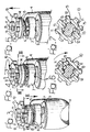
- the number 1 designates, as a whole, a cremone handle according to the invention basically comprising a hollow body 2, from the front side of which there projects a boss 3, in a position corresponding to which there is applied a manual control lever 4.
- the lever 4 is able to turn through 90° or through 180° with respect to the body 2 in order to control in rotation a shaft 5 fixed thereto, which extends within the body 2.
- a crown wheel 10 Fitted on the shaft 5, according to the modalities that will emerge more clearly from what follows, is a crown wheel 10, the teeth of which mesh, on opposite sides, with two rack assemblies (not illustrated), mounted so that they can slide longitudinally in mutually opposite directions within the body 2 for actuating, via respective control sliders, the closing members of the door or window frame to which the handle 1 is designed to be applied.
- the positioning device comprises a helical compression spring 6 wound around the shaft 5 and set between a reaction bushing 7, mounted stationary with respect to the body 2 and traversed coaxially in a slidable manner by the shaft 5, and a resting ring 8 carried by the shaft 5.
- the reaction bushing 7, which is normally made of self-lubricating plastic material is formed with slots 9, which are designed to cooperate, as a result of rotation of the lever 4, with corresponding positioning projections (not visible in the drawings).
- the crown wheel 10 For fitting of the crown wheel 10 on the shaft 5, the latter is formed with one or, more conveniently, a pair of diametrically opposite axial grooves 11, each of which is in communication - at a certain distance from the free end of the shaft 5 - with a respective lateral seat 12.
- the crown wheel 10 is in turn made with one or, more conveniently, a pair of internal radial projections 13 which can be slidably engaged along the grooves 11 and in the corresponding lateral seats 12 of the shaft 5.
- the resting ring 8, or else a bushing 14 resting against said ring or fixed to the ring 8, is able to slide on the shaft 5 and has a pair of axial key appendages 15 slidably engaged in the axial grooves 11 of the shaft 5.
- the crown wheel 10 is inserted axially on the free end of the shaft 5, engaging the radial projections 13 within the axial grooves 11.
- the crown wheel 10 is then translated axially in the direction of the handle 4, at the same time causing the resting ring 8 with the corresponding bushing 14 to move backwards as a result of the thrust of the crown wheel 10 itself or with manual aid against the action of the spring 6, until the key appendages 15 are positioned underneath the toothed lateral seats 12.
- the crown wheel 10 can thus be positioned axially along the shaft 5 so that the two radial projections 13 will be set in a position axially corresponding to the seats 12, as illustrated in Figures 3 and 6.
- the crown wheel 10 is caused to turn (in a clockwise direction, as viewed in the figures) so as to engage the radial projections 13 within the lateral seats 12 of the shaft 15 in the way represented in Figures 4 and 7.
- the annular resting element is axially released, i.e., the corresponding axial key appendages 15 are able to slide along the grooves 11 under the action of the force of elastic return of the spring 6.
- the radial projections 13 of the crown wheel 10 are firmly blocked within the lateral seats 12 of the shaft 5 by the axial key appendages 15, which traverse the crown wheel 10. In this way, the crown wheel 10 is rendered stably fixed in rotation to the shaft 5.
- the system for fitting the crown wheel 10 of the cremone handle 1 according to the invention is obtained by means of a bayonet-joint system, which uses, as elastic element of the joint, the spring 6 already present on the snap-action positioning device of the control lever 4.
- the said fitting system proves not only simpler and less expensive, but also appreciably safer and more reliable, in so far as it guarantees a firm torsional blocking without any play between the crown wheel 10 and the shaft 5, even following upon a prolonged working life of the cremone handle.
- the resting ring 8 and the bushing 14 may be made of a single monolithic piece.
Landscapes
- Engineering & Computer Science (AREA)
- Mechanical Engineering (AREA)
- Window Of Vehicle (AREA)
- Mechanical Control Devices (AREA)
- Digital Computer Display Output (AREA)
- Lock And Its Accessories (AREA)
- Securing Of Glass Panes Or The Like (AREA)
- Special Wing (AREA)
Claims (5)
- Verschlusshandgriff (1) für Tür- und Fensterrahmen, aufweisend ein Gehäuse (2), welches einen drehbaren Steuerhebel (4) trägt, an welchem in Drehung ein Schaft (5) befestigt ist, der ein Kranzrad (10) trägt, und in welchem betriebsmäßig dem Schaft (5) eine Schnapppositioniervorrichtung (6, 7, 8, 9) zum Positionieren des Steuerhebels (4) zugeordnet ist, wobei der Handgriff dadurch gekennzeichnet, dass das Kranzrad (10) mit dem Schaft (5) mit Hilfe eines Bajonettverschlusses (11, 12, 13, 6) verbunden ist, welcher die Schnapppositioniervorrichtung (6, 7, 8) benutzt.
- Verschlusshandgriff nach Anspruch 1, in welchem die Schnapppositioniervorrichtung eine spiralförmige Feder (6) aufweist, die koaxial auf dem Schaft (5) zwischen einem vom Schaft selbst getragenen Stützelement (8) und einer Reaktionshülse (7) sitzt, dadurch gekennzeichnet, dass der Schaft (5) mindestens eine axiale Nut (11) hat, von welcher sich ein seitlicher Sitz (12) abzweigt, und dass das Kranzrad (10) innen mit mindestens einem radialen Vorsprung (13) ausgebildet ist, welcher gleitbar in die axiale Nut (11) und den seitlichen Sitz (12) des Schaftes (5) als Ergebnis seiner axialen Translation längs des Schaftes gegen das Stützelement (8) der spiralförmigen Feder (6) eingreift, gefolgt von seiner Winkelverschiebung in Bezug auf den Schaft (5).
- Verschlusshandgriff nach Anspruch 2, dadurch gekennzeichnet, dass das Stützelement (8) einen Ring (14) mit mindestens einem axialen Schlüsselansatz (15) aufweist, der gleitbar in die axiale Nut (11) des Schaftes (5) eingreift, um das Kranzrad (10) winkelmäßig zu blockieren folgend dem Eingriff des radialen Vorsprungs (13) innerhalb des seitlichen Sitzes (12).
- Verschlusshandgriff nach Anspruch 2 und 3, dadurch gekennzeichnet, dass der Schaft (5) ein Paar von diametral gegenüberliegenden axialen Nuten (11), das Kranzrad (10) ein Paar von diametral gegenüberliegenden radialen Vorsprüngen (13) und der Ring (14) ein Paar von diametral gegenüberliegenden axialen Schlüsselansätzen (15) hat.
- Verschlusshandgriff nach Anspruch 3, dadurch gekennzeichnet, dass der Ring (14) aus einem Stück mit dem Stützelement (8) besteht.
Applications Claiming Priority (2)
| Application Number | Priority Date | Filing Date | Title |
|---|---|---|---|
| IT2002TO000353A ITTO20020353A1 (it) | 2002-04-24 | 2002-04-24 | Maniglia cremonese per serramenti. |
| ITTO20020353 | 2002-04-24 |
Publications (2)
| Publication Number | Publication Date |
|---|---|
| EP1361326A1 EP1361326A1 (de) | 2003-11-12 |
| EP1361326B1 true EP1361326B1 (de) | 2005-01-26 |
Family
ID=27639027
Family Applications (1)
| Application Number | Title | Priority Date | Filing Date |
|---|---|---|---|
| EP03006446A Expired - Lifetime EP1361326B1 (de) | 2002-04-24 | 2003-03-21 | Treibstangenbeschlag mit Handgriff für Tür- und Fensterrahmen |
Country Status (6)
| Country | Link |
|---|---|
| EP (1) | EP1361326B1 (de) |
| AT (1) | ATE288013T1 (de) |
| DE (1) | DE60300286D1 (de) |
| ES (1) | ES2236637T3 (de) |
| IT (1) | ITTO20020353A1 (de) |
| PT (1) | PT1361326E (de) |
Family Cites Families (4)
| Publication number | Priority date | Publication date | Assignee | Title |
|---|---|---|---|---|
| DE9012497U1 (de) * | 1990-08-31 | 1990-12-13 | Roto Frank AG, 7022 Leinfelden-Echterdingen | Beschlag für ein Fenster, eine Tür o.dgl. |
| IT232178Y1 (it) * | 1993-03-22 | 1999-12-17 | Accessori S R L Centro | Cinematismo per chiusure a cremonese per serramenti. |
| EP0874119B1 (de) * | 1997-04-25 | 2003-06-18 | Medal S.r.l. | Handgriff vom sogenannten Schliessbolzentyp |
| DE20009771U1 (de) * | 2000-06-02 | 2000-09-07 | Emka Beschlagteile Gmbh & Co. Kg, 42551 Velbert | Stangenschloß für ein Verschlußsystem |
-
2002
- 2002-04-24 IT IT2002TO000353A patent/ITTO20020353A1/it unknown
-
2003
- 2003-03-21 EP EP03006446A patent/EP1361326B1/de not_active Expired - Lifetime
- 2003-03-21 DE DE60300286T patent/DE60300286D1/de not_active Expired - Lifetime
- 2003-03-21 PT PT03006446T patent/PT1361326E/pt unknown
- 2003-03-21 ES ES03006446T patent/ES2236637T3/es not_active Expired - Lifetime
- 2003-03-21 AT AT03006446T patent/ATE288013T1/de not_active IP Right Cessation
Also Published As
| Publication number | Publication date |
|---|---|
| ITTO20020353A0 (it) | 2002-04-24 |
| ES2236637T3 (es) | 2005-07-16 |
| ATE288013T1 (de) | 2005-02-15 |
| EP1361326A1 (de) | 2003-11-12 |
| PT1361326E (pt) | 2005-05-31 |
| ITTO20020353A1 (it) | 2003-10-24 |
| DE60300286D1 (de) | 2005-03-03 |
Similar Documents
| Publication | Publication Date | Title |
|---|---|---|
| US6286183B1 (en) | Caster with securing device | |
| EP2664734B1 (de) | Entriegelvorrichtung für fahrzeugtür | |
| US6076304A (en) | Window opening and closing assembly | |
| EP0267423A2 (de) | Kraftfahrzeugtür-Verriegelungsvorrichtung | |
| CA1320241C (en) | Actuator for automotive door locking device | |
| US5125701A (en) | Child protecting mechanism in door lock apparatus | |
| KR900002523Y1 (ko) | 터언 시그널 스위치의 캔슬 기구 | |
| KR20060053945A (ko) | 듀얼 베어링 릴의 드래그 조정 장치 | |
| US20180112442A1 (en) | Door lock apparatus | |
| US5083823A (en) | Latch bolt operating device with lever handles and improved privacy lock mechanism | |
| CN110036165A (zh) | 窗和门开关机构 | |
| US20050126329A1 (en) | Shifter for a bicycle transmission | |
| EP1361326B1 (de) | Treibstangenbeschlag mit Handgriff für Tür- und Fensterrahmen | |
| JPS62234A (ja) | 魚釣用リ−ルのクラツチ機構 | |
| JPH064129Y2 (ja) | シフトレバー装置 | |
| US6212335B1 (en) | Driving mechanism of lens barrier and zoom lens for camera | |
| US20240318475A1 (en) | Locking means for a front flap of a motor vehicle | |
| US11028912B2 (en) | Drive arrangement for motorized adjustment of an actuating element rotatably mounted in a motor vehicle door latch housing | |
| JP7187796B2 (ja) | ドアクローザ | |
| WO2017126321A1 (ja) | 減速機および減速機付きモータ | |
| JP2001305409A (ja) | レンズ鏡筒 | |
| JP3810476B2 (ja) | レンズバリアの開閉装置 | |
| KR200248023Y1 (ko) | 도어록의손잡이구 | |
| EP1801326A1 (de) | Verriegelunganordnung und abschliessbarer Fenstergriff | |
| JPH0536049Y2 (de) |
Legal Events
| Date | Code | Title | Description |
|---|---|---|---|
| PUAI | Public reference made under article 153(3) epc to a published international application that has entered the european phase |
Free format text: ORIGINAL CODE: 0009012 |
|
| AK | Designated contracting states |
Kind code of ref document: A1 Designated state(s): AT BE BG CH CY CZ DE DK EE ES FI FR GB GR HU IE IT LI LU MC NL PT RO SE SI SK TR |
|
| AX | Request for extension of the european patent |
Extension state: AL LT LV MK |
|
| 17P | Request for examination filed |
Effective date: 20040430 |
|
| GRAP | Despatch of communication of intention to grant a patent |
Free format text: ORIGINAL CODE: EPIDOSNIGR1 |
|
| AKX | Designation fees paid |
Designated state(s): AT BE BG CH CY CZ DE DK EE ES FI FR GB GR HU IE IT LI LU MC NL PT RO SE SI SK TR |
|
| GRAS | Grant fee paid |
Free format text: ORIGINAL CODE: EPIDOSNIGR3 |
|
| GRAA | (expected) grant |
Free format text: ORIGINAL CODE: 0009210 |
|
| AK | Designated contracting states |
Kind code of ref document: B1 Designated state(s): AT BE BG CH CY CZ DE DK EE ES FI FR GB GR HU IE IT LI LU MC NL PT RO SE SI SK TR |
|
| PG25 | Lapsed in a contracting state [announced via postgrant information from national office to epo] |
Ref country code: LI Free format text: LAPSE BECAUSE OF FAILURE TO SUBMIT A TRANSLATION OF THE DESCRIPTION OR TO PAY THE FEE WITHIN THE PRESCRIBED TIME-LIMIT Effective date: 20050126 Ref country code: BE Free format text: LAPSE BECAUSE OF FAILURE TO SUBMIT A TRANSLATION OF THE DESCRIPTION OR TO PAY THE FEE WITHIN THE PRESCRIBED TIME-LIMIT Effective date: 20050126 Ref country code: AT Free format text: LAPSE BECAUSE OF FAILURE TO SUBMIT A TRANSLATION OF THE DESCRIPTION OR TO PAY THE FEE WITHIN THE PRESCRIBED TIME-LIMIT Effective date: 20050126 Ref country code: RO Free format text: LAPSE BECAUSE OF FAILURE TO SUBMIT A TRANSLATION OF THE DESCRIPTION OR TO PAY THE FEE WITHIN THE PRESCRIBED TIME-LIMIT Effective date: 20050126 Ref country code: SK Free format text: LAPSE BECAUSE OF FAILURE TO SUBMIT A TRANSLATION OF THE DESCRIPTION OR TO PAY THE FEE WITHIN THE PRESCRIBED TIME-LIMIT Effective date: 20050126 Ref country code: NL Free format text: LAPSE BECAUSE OF FAILURE TO SUBMIT A TRANSLATION OF THE DESCRIPTION OR TO PAY THE FEE WITHIN THE PRESCRIBED TIME-LIMIT Effective date: 20050126 Ref country code: FI Free format text: LAPSE BECAUSE OF FAILURE TO SUBMIT A TRANSLATION OF THE DESCRIPTION OR TO PAY THE FEE WITHIN THE PRESCRIBED TIME-LIMIT Effective date: 20050126 Ref country code: EE Free format text: LAPSE BECAUSE OF FAILURE TO SUBMIT A TRANSLATION OF THE DESCRIPTION OR TO PAY THE FEE WITHIN THE PRESCRIBED TIME-LIMIT Effective date: 20050126 Ref country code: SI Free format text: LAPSE BECAUSE OF FAILURE TO SUBMIT A TRANSLATION OF THE DESCRIPTION OR TO PAY THE FEE WITHIN THE PRESCRIBED TIME-LIMIT Effective date: 20050126 Ref country code: TR Free format text: LAPSE BECAUSE OF FAILURE TO SUBMIT A TRANSLATION OF THE DESCRIPTION OR TO PAY THE FEE WITHIN THE PRESCRIBED TIME-LIMIT Effective date: 20050126 Ref country code: CZ Free format text: LAPSE BECAUSE OF FAILURE TO SUBMIT A TRANSLATION OF THE DESCRIPTION OR TO PAY THE FEE WITHIN THE PRESCRIBED TIME-LIMIT Effective date: 20050126 Ref country code: CH Free format text: LAPSE BECAUSE OF FAILURE TO SUBMIT A TRANSLATION OF THE DESCRIPTION OR TO PAY THE FEE WITHIN THE PRESCRIBED TIME-LIMIT Effective date: 20050126 Ref country code: BG Free format text: LAPSE BECAUSE OF FAILURE TO SUBMIT A TRANSLATION OF THE DESCRIPTION OR TO PAY THE FEE WITHIN THE PRESCRIBED TIME-LIMIT Effective date: 20050126 Ref country code: IT Free format text: LAPSE BECAUSE OF FAILURE TO SUBMIT A TRANSLATION OF THE DESCRIPTION OR TO PAY THE FEE WITHIN THE PRESCRIBED TIME-LIMIT;WARNING: LAPSES OF ITALIAN PATENTS WITH EFFECTIVE DATE BEFORE 2007 MAY HAVE OCCURRED AT ANY TIME BEFORE 2007. THE CORRECT EFFECTIVE DATE MAY BE DIFFERENT FROM THE ONE RECORDED. Effective date: 20050126 |
|
| REG | Reference to a national code |
Ref country code: GB Ref legal event code: FG4D |
|
| REG | Reference to a national code |
Ref country code: CH Ref legal event code: EP |
|
| REG | Reference to a national code |
Ref country code: IE Ref legal event code: FG4D |
|
| REF | Corresponds to: |
Ref document number: 60300286 Country of ref document: DE Date of ref document: 20050303 Kind code of ref document: P |
|
| PG25 | Lapsed in a contracting state [announced via postgrant information from national office to epo] |
Ref country code: CY Free format text: LAPSE BECAUSE OF FAILURE TO SUBMIT A TRANSLATION OF THE DESCRIPTION OR TO PAY THE FEE WITHIN THE PRESCRIBED TIME-LIMIT Effective date: 20050321 Ref country code: LU Free format text: LAPSE BECAUSE OF NON-PAYMENT OF DUE FEES Effective date: 20050321 Ref country code: IE Free format text: LAPSE BECAUSE OF NON-PAYMENT OF DUE FEES Effective date: 20050321 |
|
| PG25 | Lapsed in a contracting state [announced via postgrant information from national office to epo] |
Ref country code: MC Free format text: LAPSE BECAUSE OF NON-PAYMENT OF DUE FEES Effective date: 20050331 |
|
| PG25 | Lapsed in a contracting state [announced via postgrant information from national office to epo] |
Ref country code: SE Free format text: LAPSE BECAUSE OF FAILURE TO SUBMIT A TRANSLATION OF THE DESCRIPTION OR TO PAY THE FEE WITHIN THE PRESCRIBED TIME-LIMIT Effective date: 20050426 Ref country code: DK Free format text: LAPSE BECAUSE OF FAILURE TO SUBMIT A TRANSLATION OF THE DESCRIPTION OR TO PAY THE FEE WITHIN THE PRESCRIBED TIME-LIMIT Effective date: 20050426 Ref country code: GR Free format text: LAPSE BECAUSE OF FAILURE TO SUBMIT A TRANSLATION OF THE DESCRIPTION OR TO PAY THE FEE WITHIN THE PRESCRIBED TIME-LIMIT Effective date: 20050426 |
|
| PG25 | Lapsed in a contracting state [announced via postgrant information from national office to epo] |
Ref country code: DE Free format text: LAPSE BECAUSE OF FAILURE TO SUBMIT A TRANSLATION OF THE DESCRIPTION OR TO PAY THE FEE WITHIN THE PRESCRIBED TIME-LIMIT Effective date: 20050427 Ref country code: HU Free format text: LAPSE BECAUSE OF FAILURE TO SUBMIT A TRANSLATION OF THE DESCRIPTION OR TO PAY THE FEE WITHIN THE PRESCRIBED TIME-LIMIT Effective date: 20050427 |
|
| REG | Reference to a national code |
Ref country code: PT Ref legal event code: SC4A Free format text: AVAILABILITY OF NATIONAL TRANSLATION Effective date: 20050324 |
|
| NLV1 | Nl: lapsed or annulled due to failure to fulfill the requirements of art. 29p and 29m of the patents act | ||
| REG | Reference to a national code |
Ref country code: ES Ref legal event code: FG2A Ref document number: 2236637 Country of ref document: ES Kind code of ref document: T3 |
|
| REG | Reference to a national code |
Ref country code: CH Ref legal event code: PL |
|
| PLBE | No opposition filed within time limit |
Free format text: ORIGINAL CODE: 0009261 |
|
| STAA | Information on the status of an ep patent application or granted ep patent |
Free format text: STATUS: NO OPPOSITION FILED WITHIN TIME LIMIT |
|
| REG | Reference to a national code |
Ref country code: IE Ref legal event code: MM4A |
|
| ET | Fr: translation filed | ||
| 26N | No opposition filed |
Effective date: 20051027 |
|
| GBPC | Gb: european patent ceased through non-payment of renewal fee |
Effective date: 20070321 |
|
| PG25 | Lapsed in a contracting state [announced via postgrant information from national office to epo] |
Ref country code: GB Free format text: LAPSE BECAUSE OF NON-PAYMENT OF DUE FEES Effective date: 20070321 |
|
| PGFP | Annual fee paid to national office [announced via postgrant information from national office to epo] |
Ref country code: FR Payment date: 20130325 Year of fee payment: 11 Ref country code: ES Payment date: 20130313 Year of fee payment: 11 |
|
| PGFP | Annual fee paid to national office [announced via postgrant information from national office to epo] |
Ref country code: PT Payment date: 20130320 Year of fee payment: 11 |
|
| REG | Reference to a national code |
Ref country code: PT Ref legal event code: MM4A Free format text: LAPSE DUE TO NON-PAYMENT OF FEES Effective date: 20140922 |
|
| REG | Reference to a national code |
Ref country code: FR Ref legal event code: ST Effective date: 20141128 |
|
| PG25 | Lapsed in a contracting state [announced via postgrant information from national office to epo] |
Ref country code: PT Free format text: LAPSE BECAUSE OF NON-PAYMENT OF DUE FEES Effective date: 20140922 |
|
| PG25 | Lapsed in a contracting state [announced via postgrant information from national office to epo] |
Ref country code: FR Free format text: LAPSE BECAUSE OF NON-PAYMENT OF DUE FEES Effective date: 20140331 |
|
| REG | Reference to a national code |
Ref country code: ES Ref legal event code: FD2A Effective date: 20150424 |
|
| PG25 | Lapsed in a contracting state [announced via postgrant information from national office to epo] |
Ref country code: ES Free format text: LAPSE BECAUSE OF NON-PAYMENT OF DUE FEES Effective date: 20140322 |