EP1361123A2 - Seat belt anchorage plate and method of manufacturing thereof - Google Patents
Seat belt anchorage plate and method of manufacturing thereof Download PDFInfo
- Publication number
- EP1361123A2 EP1361123A2 EP20030018277 EP03018277A EP1361123A2 EP 1361123 A2 EP1361123 A2 EP 1361123A2 EP 20030018277 EP20030018277 EP 20030018277 EP 03018277 A EP03018277 A EP 03018277A EP 1361123 A2 EP1361123 A2 EP 1361123A2
- Authority
- EP
- European Patent Office
- Prior art keywords
- belt
- protrusion
- long edge
- seat belt
- edge part
- Prior art date
- Legal status (The legal status is an assumption and is not a legal conclusion. Google has not performed a legal analysis and makes no representation as to the accuracy of the status listed.)
- Withdrawn
Links
Images


Classifications
-
- B—PERFORMING OPERATIONS; TRANSPORTING
- B60—VEHICLES IN GENERAL
- B60R—VEHICLES, VEHICLE FITTINGS, OR VEHICLE PARTS, NOT OTHERWISE PROVIDED FOR
- B60R22/00—Safety belts or body harnesses in vehicles
- B60R22/34—Belt retractors, e.g. reels
- B60R22/44—Belt retractors, e.g. reels with means for reducing belt tension during use under normal conditions
-
- B—PERFORMING OPERATIONS; TRANSPORTING
- B21—MECHANICAL METAL-WORKING WITHOUT ESSENTIALLY REMOVING MATERIAL; PUNCHING METAL
- B21C—MANUFACTURE OF METAL SHEETS, WIRE, RODS, TUBES OR PROFILES, OTHERWISE THAN BY ROLLING; AUXILIARY OPERATIONS USED IN CONNECTION WITH METAL-WORKING WITHOUT ESSENTIALLY REMOVING MATERIAL
- B21C37/00—Manufacture of metal sheets, bars, wire, tubes or like semi-manufactured products, not otherwise provided for; Manufacture of tubes of special shape
- B21C37/06—Manufacture of metal sheets, bars, wire, tubes or like semi-manufactured products, not otherwise provided for; Manufacture of tubes of special shape of tubes or metal hoses; Combined procedures for making tubes, e.g. for making multi-wall tubes
- B21C37/15—Making tubes of special shape; Making tube fittings
- B21C37/28—Making tube fittings for connecting pipes, e.g. U-pieces
- B21C37/29—Making branched pieces, e.g. T-pieces
- B21C37/292—Forming collars by drawing or pushing a rigid forming tool through an opening in the tube wall
-
- B—PERFORMING OPERATIONS; TRANSPORTING
- B21—MECHANICAL METAL-WORKING WITHOUT ESSENTIALLY REMOVING MATERIAL; PUNCHING METAL
- B21D—WORKING OR PROCESSING OF SHEET METAL OR METAL TUBES, RODS OR PROFILES WITHOUT ESSENTIALLY REMOVING MATERIAL; PUNCHING METAL
- B21D22/00—Shaping without cutting, by stamping, spinning, or deep-drawing
- B21D22/02—Stamping using rigid devices or tools
- B21D22/04—Stamping using rigid devices or tools for dimpling
-
- B—PERFORMING OPERATIONS; TRANSPORTING
- B21—MECHANICAL METAL-WORKING WITHOUT ESSENTIALLY REMOVING MATERIAL; PUNCHING METAL
- B21K—MAKING FORGED OR PRESSED METAL PRODUCTS, e.g. HORSE-SHOES, RIVETS, BOLTS OR WHEELS
- B21K1/00—Making machine elements
- B21K1/28—Making machine elements wheels; discs
-
- B—PERFORMING OPERATIONS; TRANSPORTING
- B21—MECHANICAL METAL-WORKING WITHOUT ESSENTIALLY REMOVING MATERIAL; PUNCHING METAL
- B21K—MAKING FORGED OR PRESSED METAL PRODUCTS, e.g. HORSE-SHOES, RIVETS, BOLTS OR WHEELS
- B21K1/00—Making machine elements
- B21K1/76—Making machine elements elements not mentioned in one of the preceding groups
-
- B—PERFORMING OPERATIONS; TRANSPORTING
- B21—MECHANICAL METAL-WORKING WITHOUT ESSENTIALLY REMOVING MATERIAL; PUNCHING METAL
- B21K—MAKING FORGED OR PRESSED METAL PRODUCTS, e.g. HORSE-SHOES, RIVETS, BOLTS OR WHEELS
- B21K23/00—Making other articles
- B21K23/04—Making other articles flanged articles
-
- B—PERFORMING OPERATIONS; TRANSPORTING
- B60—VEHICLES IN GENERAL
- B60R—VEHICLES, VEHICLE FITTINGS, OR VEHICLE PARTS, NOT OTHERWISE PROVIDED FOR
- B60R21/00—Arrangements or fittings on vehicles for protecting or preventing injuries to occupants or pedestrians in case of accidents or other traffic risks
- B60R21/02—Occupant safety arrangements or fittings, e.g. crash pads
- B60R21/16—Inflatable occupant restraints or confinements designed to inflate upon impact or impending impact, e.g. air bags
- B60R21/18—Inflatable occupant restraints or confinements designed to inflate upon impact or impending impact, e.g. air bags the inflatable member formed as a belt or harness or combined with a belt or harness arrangement
-
- B—PERFORMING OPERATIONS; TRANSPORTING
- B60—VEHICLES IN GENERAL
- B60R—VEHICLES, VEHICLE FITTINGS, OR VEHICLE PARTS, NOT OTHERWISE PROVIDED FOR
- B60R22/00—Safety belts or body harnesses in vehicles
- B60R22/18—Anchoring devices
-
- B—PERFORMING OPERATIONS; TRANSPORTING
- B60—VEHICLES IN GENERAL
- B60R—VEHICLES, VEHICLE FITTINGS, OR VEHICLE PARTS, NOT OTHERWISE PROVIDED FOR
- B60R22/00—Safety belts or body harnesses in vehicles
- B60R22/18—Anchoring devices
- B60R22/24—Anchoring devices secured to the side, door, or roof of the vehicle
-
- Y—GENERAL TAGGING OF NEW TECHNOLOGICAL DEVELOPMENTS; GENERAL TAGGING OF CROSS-SECTIONAL TECHNOLOGIES SPANNING OVER SEVERAL SECTIONS OF THE IPC; TECHNICAL SUBJECTS COVERED BY FORMER USPC CROSS-REFERENCE ART COLLECTIONS [XRACs] AND DIGESTS
- Y10—TECHNICAL SUBJECTS COVERED BY FORMER USPC
- Y10T—TECHNICAL SUBJECTS COVERED BY FORMER US CLASSIFICATION
- Y10T29/00—Metal working
- Y10T29/49—Method of mechanical manufacture
- Y10T29/49616—Structural member making
- Y10T29/49622—Vehicular structural member making
-
- Y—GENERAL TAGGING OF NEW TECHNOLOGICAL DEVELOPMENTS; GENERAL TAGGING OF CROSS-SECTIONAL TECHNOLOGIES SPANNING OVER SEVERAL SECTIONS OF THE IPC; TECHNICAL SUBJECTS COVERED BY FORMER USPC CROSS-REFERENCE ART COLLECTIONS [XRACs] AND DIGESTS
- Y10—TECHNICAL SUBJECTS COVERED BY FORMER USPC
- Y10T—TECHNICAL SUBJECTS COVERED BY FORMER US CLASSIFICATION
- Y10T29/00—Metal working
- Y10T29/49—Method of mechanical manufacture
- Y10T29/49995—Shaping one-piece blank by removing material
-
- Y—GENERAL TAGGING OF NEW TECHNOLOGICAL DEVELOPMENTS; GENERAL TAGGING OF CROSS-SECTIONAL TECHNOLOGIES SPANNING OVER SEVERAL SECTIONS OF THE IPC; TECHNICAL SUBJECTS COVERED BY FORMER USPC CROSS-REFERENCE ART COLLECTIONS [XRACs] AND DIGESTS
- Y10—TECHNICAL SUBJECTS COVERED BY FORMER USPC
- Y10T—TECHNICAL SUBJECTS COVERED BY FORMER US CLASSIFICATION
- Y10T83/00—Cutting
- Y10T83/04—Processes
- Y10T83/06—Blanking
Definitions
- the present invention relates to a seat belt anchorage plate formed by a belt mounting clamp for a seat belt device for attaching the end of, for example, a seat belt for an automobile to a fixed part such as a vehicle body.
- the present invention also relates to a method for manufacturing such a seat belt anchorage plate.
- a belt mounting clamp comprises a base (plate shaped member) 2 having a bolt hole 3 and a slot 69 formed thereon and is designed to be secured to a fixed part such as a vehicle body through the belt hole 3 and to be connected to a belt 13 through the slot 69.
- the belt 13 employs a thin band shaped woven fabric in which for example, polyester fibers are woven and is folded back in one long edge part 691 of the slot 69, so that tension is exerted on the one long edge part 691 which is linearly formed.
- the above mentioned conventional belt mounting clamp has one long edge part 691 formed in a straight line, when the tension of the belt 13 is not exerted in the direction perpendicular to the one long edge part 691, the belt 13 is liable to laterally slide on the one long edge part 691 and come together to the end part of the long edge part 691. In other words, there has been encountered a problem that the belt is apt to be gathered to the end part of one long edge part 691.
- the belt 13 Even if the tension of the belt 13 is exerted in the direction perpendicular to the one long edge part 691, for example, according to an examination through a strength measuring test, the belt 13 itself will be thinly converged and tend to meet at one part on the one long edge part 691 when the tension is exerted on the belt 13. Further, since the one long edge part 691 is elastically bent and slightly recessed by virtue of the tension of the belt 13, the belt 13 is undesirably liable to be gathered to one part on the long edge part 691 in addition to the defect that the belt 13 itself thinly converges into one part.
- the belt 13 is advantageously curved so as to be folded along a center line in its longitudinal direction in order to maintain the flat state of the belt 13. Therefore, the belt 13 is normally inserted into the slot 69 under its curved state as stated above.
- the belt 13 is curved in such a way, there arises a problem that both ends at the right and left sides of the belt 13 abut against, for example, both right and left ends of the one long edge part 691, and therefore, the belt 13 is inserted into the slot 69 with difficulty.
- Fig.38 when both the end parts of the belt 13 swell out roundly, there also arises a problem that these swelling parts tend to more easily abut against both the end parts of one long edge part 691.
- the slot 69 is formed by a press working.
- burs are liable to be formed at the corner parts in the side punched out by a press. When such burs are left as they are, they have possibility to cause an action similar to that of a cutter.
- the corner parts are ordinarily subjected to a rounding finish independent of a press working process, or a coating work to cover the entire corner parts with vinyl chloride or polyethylene or the like. As a result, a problem has been encountered in terms of cost-up owing to such a finishing work or a coating work.
- a belt mounting clamp is formed with a plate shaped base 2, the area of one long edge part 691 for holding the belt 13 is small, so that surface pressure exerting on the belt 13 is disadvantageously increased.
- the present invention was made by taking these problems into account and an object of the present invention is to provide a seat belt anchorage plate forming a belt mounting clamp for a seat belt device capable of completely reducing surface pressure to be exerted on the belt even when tension acts on the belt.
- the seat belt anchorage plate as defined in claims 1 to 6.
- Another object is to provide a method of manufacturing such a seat belt anchorage plate. Such an object is achieved through the method defined in claims 7 to 12.
- Such a seat belt anchorage plate can serve as a belt mounting clamp for a seat belt device which is formed with a plate shaped member, the plate shaped member having a slot formed into which the belt is inserted; the slot having long edge parts opposed to each other one of which bears the tension of the belt folded back therein.
- the one long edge part has a protrusion which protrudes from one surface side of the plate shaped member, the contact surface area of the belt abutting against the one long edge part is increased. As a result, the surface pressure of the belt can be reduced. Further, since the corner parts of the one long edge part are rounded along the direction in which the belt is folded back, the belt is prevented from breaking in the corner parts. Furthermore, since the corner parts are rounded and these corner parts do not need to undergo a coating work with vinyl chloride or polyethylene or the like, the cost required for such a coating work can be reduced. That is, the cost can be lowered.
- a protrusion which protrudes from the other surface of the plate shaped member is formed by bending a part of the plate shaped member from the one surface side to the other surface side of the plate shaped member, the protrusion can be projected greatly from the other surface side. Therefore, the area of the belt abutting against the one long edge part can be increased. In other words, surface pressure exerted on the belt from the one long edge part can be completely lowered. Therefore, the durability of the belt and the strength of the belt mounting clamp can be improved, and safety can be improved based on the improvement of their durability and strength. Further, since the corner parts of the one long edge part are rounded, the belt can be prevented from being broken in these corner parts. Additionally, since the corner parts are rounded and do not need to be subjected to a coating work with vinyl chloride or polyethylene or the like, the cost necessary for such a coating work can be reduced. Namely, the cost can be lowered.
- the one long edge part is formed so as to have one protrusion and the other protrusion which respectively protrude from one surface side and the other surface side of the plate shaped member, the contact surface area of the belt which abuts against the one long edge part is increased. As a result, the surface pressure of the belt can be further reduced.
- the one long edge part is formed so as to have one protrusion and the other protrusion which respectively protrude from one surface side and the other surface side by bending a part of the plate shaped member from the one surface side to the other surface side of the plate shaped member and pressing the bent part to return to surface side, the area of a part against which the belt abuts can be increased. Consequently, the surface pressure of the folded-back part of the belt can be furthermore reduced.
- the short edge parts are also provided with a protrusion, so that the strength of the short edge parts can be increased. Therefore, even if the belt is gathered to the short edge part so that force is concentrated to the short edge part, the safety of the short edge part can be more improved than the past until the present.
- the strength of an entire part around the slot can be improved.
- the short edges are formed to be curved in a circular arc shape, the concentration of stress to the short edge parts can be relieved.
- the contact surface area the belt which abuts against the one long edge part can be increased owing to the presence of the protrusion.
- the surface pressure of the belt can be reduced.
- the protrusions are formed so as to protrude from both the one surface side and the other surface side of the plate member, the surface pressure of the belt can be most reduced.
- the belt can be prevented from being broken in these corner parts. Further, since the corner parts are rounded and they do not need to undergo a coating work with vinyl chloride or polyethylene or the like, expenses required for such a coating work can be reduced. That is, the cost can be lowered.
- a seat belt anchorage plate Embodiments of a seat belt anchorage plate will be described hereinbelow with reference to Figs. 1 to 37. Initially, referring to Figs. 1 to 5, a first example of a seat belt anchorage plate will be described below, which is not part of the present invention.
- S designates the vehicle body of an automobile, D a driver's seat, and 1 a seat belt device.
- a retractor 11 for a shoulder belt is fixed to the vehicle body S.
- a shoulder belt 12 is connected to this retractor 11.
- a belt mounting clamp A1 is fixed to one side of the seat D in the vehicle body S.
- a waist belt 13 is connected to this belt mounting clamp A1.
- the above described tongue clamp 14 is detachably connected to a buckle 15 which is connected to another belt mounting clamp A2 through a connecting belt 151.
- This belt mounting clamp A2 is fixed to the vehicle body S opposite to that of the belt mounting clamp A1 by sandwiching the seat D therebetween. Since these belt mounting clamps A1 and A2 have substantially the same construction, the construction of the belt mounting clamp A1 will be specifically described using its reference symbols.
- the belt mounting clamp A1 forms a seat belt anchorage plate and is made of a plate shaped base (plate shaped member) 2, and slightly bent at a bending part 2a to be formed in a " ⁇ " shape, as illustrated in Figs. 1 to 2.
- the plate shaped base 2 is constituted of a fixing plate part 21 in one side and a belt winding plate part 22 in the other side which sandwich this bending part 2a therebetween as a border.
- a bolt hole 3 is formed in the fixing plate part 21, a bolt hole 3 is formed.
- a plurality of curved protrusions 31 are formed at equal intervals in the radial direction of the peripheral edge part of the bolt hole 3 (in the illustrated example, three protrusions are formed).
- the respective curved protrusions 31 are projected from the one surface side to the other surface side of the base 2 by a press working.
- the number of the curved protrusions is not limited and the protrusions may be finely radially provided like a chrysanthemum seat.
- a fixing bolt 5 is inserted into the bolt hole 3.
- the base 2 is designed to be fixed to the vehicle body S by means of this bolt 5 and a nut 51.
- the above stated curved protrusions 31 serve as means similar to a spring washer as well as locking means for stopping rotation due to the increase of friction.
- the curved protrusions are useful for assuredly fixing the base 2 to the vehicle body S.
- the spring washer which bas been conventionally usually employed does not need to be used. Therefore, the number of parts required can be reduced.
- a slot 6 for inserting and connecting one end part of the waist belt 13 is formed on the belt winding plate part 22 of the base 2.
- the waist belt 13 is folded back in one long edge part 691 of the slot 6 so that tension is exerted on the one long edge part 691.
- the one long edge part 691 bearing the tension is curved at a central part in its longitudinal direction so as to protrude in the direction opposite to that on which the tension is exerted.
- the waist belt 13 employs a belt similar to one shown in the conventional example, a band shaped and flattened thin woven fabric into which polyester fibers are woven.
- One end part of the belt 13 in its longitudinal direction is folded back in the one long edge part 691.
- the folded-back part is sewn onto the waist belt 13 so that it is fixed to the base 2.
- the other long edge part 692 opposed to the one long edge part 691 is also curved in the direction similar to that of the one long edge part 691.
- Parts through which the one long edge part is connected to the other long edge part 692 are short edge parts 7 and 7 formed in smoothly continued circular arc shapes.
- the slot 6 comprising one and the other long edge parts 691, 692 and the short edge parts 7 and 7 is formed as illustrated in Fig. 3.
- the slot 6 has a circular arc shaped inner surface 61 formed from one surface 22a side of the base 2 to the interior of the slot 6 and a protrusion 611 protruding in a circular arc shape which is formed from the interior of the slot 6 to the other surface 22b side.
- These inner surface 61 and protrusion 611 are formed by press-working.
- the belt mounting clamp for a seat belt device constructed as mentioned above, since the central part of the one long edge part 691 is curved so as to protrude in the direction opposite to the tension of the waist belt 13, even when the one long edge part 691 is elastically deformed in the direction of the tension, the long edge part 691 is not deformed in a recessed shape in the direction of tension. Thus, the belt does not gather to the recessed part and the width of the waist belt 13 is usually maintained to a normal width. Consequently, since the tension of the belt 13 is constantly uniformly distributed on the one long edge part 691, the strength performance of the waist belt 13 and the belt mounting clamp A1 and safety can be improved depending on the improvement of their strength.
- the other long edge part 692 is also curved in a similar way to the one long edge part 691, when the waist belt 13 is inserted into the slot 6 while it is curved so as to be folded back along a central line in its longitudinal direction in order to maintain the flat state of the waist belt 13, the configurations of the one and the other long edge parts 691 and 692 substantially correspond to the curved configuration of the waist belt 13.
- the waist belt 13 can be extremely easily inserted into the slot 6.
- the connecting parts of the one and the other long edge parts 691 and 692 namely, the short edge parts 7 and 7 are shaped in smooth circular arc in configuration, even when both the end parts of the waist belt 13 along its 5 longitudinal direction are expanded in a circular arc shape, the expanded parts do not collide with the short edge parts 7 and 7. Therefore, the waist belt 13 can be advantageously readily inserted into the slot 6. In addition, both the end parts of the waist belt 13 can fit in the short edge parts 7 and 7. When tension acts on the waist belt 13, the belt 13 can be stably held in its prescribed position of the slot 6.
- the slot 6 has a circular arc shaped inner surface 61 from the one surface 22a side of the base 2 to the interior of the slot 6 and a protrusion 611 protruding in a circular arc shape from the interior of the slot 6 to the other surface 22b side. Therefore, such a possibility can be removed that the waist belt 13 folded back in the one long edge part 691 collides with the corner parts and then is cut. Additionally, since an area of the waist belt 13 which abuts against the one long edge part 691 is increased due to the existence of the protrusion 611, surface pressure exerted on the waist belt 13 can be decreased and the durability and reliability of the waist belt 13 can be improved.
- the protrusion 611 is formed on the entire periphery of the slot 6, strength in the periphery of the slot is improved and the strength of the whole belt mounting clamp A1 can be improved.
- the short edge parts 7 can be strengthened, even if the end part of the waist belt 13 gather to the short edge part 7 and force is concentrated on the short edge part 7, the safety of the short edge part can be improved more than before.
- the waist belt 13 folded back in the one long edge part 691 comes into tight contact with the one long edge part 691. More specifically stated, the folded back part of the waist belt 13 is curved in a configuration similar to that of the one long edge part 691 and the central part of the belt in its lateral direction expands. Therefore, the waist belt 13 hardly slides in its lateral direction along the one long edge part 691. Accordingly, even when the direction of the tension of the waist belt 13 does not coincide with the direction perpendicular to the one long edge part 691, the waist belt 13 does not slide sideward along the one long edge part 691 nor gather to the end part of the slot 6.
- the waist belt 13 since the central part of the waist belt 13 in the direction of its width swells in a similar manner to the one long edge part 691, the waist belt 13 is always expanded in its lateral direction. Accordingly, even when the waist belt 13 itself tends to thinly converge upon exertion of tension on the waist belt 13, the waist belt 13 is maintained in its original expanded state on the one long edge part 691. That is, the waist belt 13 does not gather to one part on the one long edge part 691. As mentioned above, since the width of the belt folded back part is appropriately maintained, the tension of the belt is uniformly transmitted to the one long edge part. Consequently, not only the durability of the belt and the strength performance of the belt mounting clamp but also safety can be improved.
- a second example which is not part of the present invention will be described. While the second example is different from the first example in that the shapes of the respective slots 6 are different from each other, the second example is similar to the first example in terms of other points. Therefore, the explanation therefor will be omitted.
- a part corresponding to the slot 6 is formed in a recessed shape by a plurality of times of press-workings, as illustrated in Figs. 6A, 6B, and 6C. Then, the bottom of the recessed part is punched out to be removed so that a protruding piece 23 which protrudes from one surface 22a side of a base 2 to the other surface 22b side is formed. At this time, a curved surface R1 is formed which is curved in a circular arc shape from the one surface 22a to the inner surface of the protruding piece 23. As can be seen in Fig.
- the end part of the protruding piece 23 is folded back by a press-working (curling work) so that it further comes near the other surface 22b.
- a protrusion 611 which largely protrudes to the other surface 22b side is formed and a curved surface R2 is formed which is smoothly curled from the inner surface of the slot 6 to the protrusion 611.
- a belt mounting clamp A1 is bent substantially at right angles with a belt winding plate part 22 in a bent part 2a.
- a slot 6 is formed on the belt winding plate part 22.
- This slot 6 is provided with one protrusion 611a and the other protrusion 611b which respectively protrude to one surface 22a side and the other surface 22b side.
- the slot 6 has an inner surface whose length is increased due to the one protrusion 611a and the other protrusion 611b, so that the area of along edge part 691 against which a waist belt 13 abuts is increased.
- the one protrusion 611a and the other protrusion 611b are respectively projected to the one surface 22a side and the other surface 22b side in such a manner that a protrusion protruding from the other surface 22b is formed by bending (burring) a part of the base 2 from the one surface 22a side of the base 2 to the other surface 22b side and moving this protrusion to the one surface 22a side by a press. Consequently, the amount of protrusion of the one protrusion 611a and the other protrusion 611b are respectively determined based on the amount of initial bending (amount of protruding) of the base 2.
- the respective protrusions 611a and 611b have their end parts rounded.
- C chamfered parts 2b are formed on the end parts of the outer periphery of the base 2.
- a marking S10 is stamped on the periphery of a bolt hole 3 on the base 2.
- the belt mounting clamp A1 constructed as stated above, since the amount of respective protrusions of the one protrusion 611 a and the other protrusion 611b can be increased depending on the amount of bending (amount of protruding) of the base 2, the area of a part in the one long edge part 691 against which the waist belt 13 abuts can be increased up to a satisfactory value as required. Therefore, surface pressure exerted upon the waist belt 13 from the one long edge part 691 can be completely lowered and safety can be improved depending on the improvement of the durability of the waist belt 13 and the strength performance of the belt mounting clamp A1.
- the waist belt 13 can be prevented from being broken on the protrusions.
- the corner parts of the protrusions are rounded and the protrusions do not need to undergo a coating work with vinyl chloride or polyethylene or the like, expenses necessary for such a coating work can be reduced, namely, the cost can be reduced.
- a first lower hole S1 for forming a slot 6 is bored on a steel plate S as the raw material of a base 2 using a metal mold K1 and a punch K2.
- a circular arc shaped roundness S1a is formed from the upper part of the first preliminary hole S1 to the upper surface of the steel plate S, using a metal mold K3 and a metal mold K4.
- a circular arc shaped roundness S1b is formed from the lower part of the first preliminary hole S1 to the lower surface of the steel plate S, using a metal mold K5 and a metal mold K6.
- a fourth step illustrated in Fig. 11 the part of the first preliminary hole S1 is curved above the steel plate S (burring work), using a metal mold K7 and a metal mold K8 so that a second preliminary hole S2 is formed.
- a fifth step as illustrated in Fig. 12 the part of the second preliminary hole S2 which protrudes upward is surface-pressed downward by using a metal mold K9, a metal mold K10 and a metal mold K11 so that a protrusion S3 and a protrusion S4 are formed which protrude with substantially the same height from the upper and lower surfaces of the steel plate S.
- the protrusion S3 which protrudes toward the upper side is finished by using a metal mold K12 and a metal mold K13 so as to have an entirely smooth curved surface (restriking work). At this time, the surface of the second preliminary hole S2 is finely finished.
- the protrusion S4 which protrudes toward the lower side is finished by using a metal mold K14 and a metal mold K15 so as to have an entirely smooth curved surface (restriking work). At this time, the surface of the second preliminary hole S2 is also finely finished.
- a slot 6 is formed with the second preliminary hole S2 finished in such a way and one protrusion 611a and the other protrusion 611a are formed with the protrusions S3 and S4.
- a bolt hole 3 is bored on the steel plate S and markings are stamped on the periphery of the bolt hole 3 by using a metal mold K21, a punch K22 and marking presses K23 and K24.
- a product is in a state in which the bolt hole 3 is bored and the markings S10 are stamped.
- a ninth step as shown in Fig. 17 the outer periphery of a belt mounting clamp is cut (trimming work) by using a metal mold K25, metal molds K 26 and metal molds K27.
- the steel plate S which forms a belt mounting clamp is bent substantially at right angles with the rest of the steel plate S along a bent part 2a by employing a metal mold K31 and a metal mold K32.
- a belt mounting clamp A1 as shown in Fig. 22 is completed.
- the belt mounting clamp A1 is formed with the steel plate S by press-workings.
- the manufacturing method of the belt mounting clamp has been divided into the eleven steps and these steps have been individually explained according to the above description, this manufacturing method is actually divided into still more steps so that the material is gradually deformed until the belt mounting clamp is formed therewith.
- the protrusions protrude on both the one surface 22a and the other surface 22b side of the base 2, the protrusion may only protrude either on one surface 22a or on the other surface 22b.
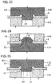
- a method for forming the protrusion protruding only on one side may be achieved by carrying out fifth to seventh steps shown in Figs. 23 to 25 after the fourth step shown in Fig.11.
- the part of the second preliminary hole S2 which protrudes to the upper side is surface-pressed to the lower side by using a metal mold K15 and a metal mold K16.
- a protrusion S3 is formed which protrudes with a substantially constant height from the upper surface of the steel plate S.
- a sixth step as illustrated in Fig. 24 an edge S5 opposite to the protrusion S3 protruding to the upper side is finished so as to have a smooth curved surface by employing a metal mold K17 and a metal mold K18. At this time, the surface of the second preliminary hole 2 is also clearly finished.
- the protrusion S3 protruding to the upper side is subjected to a finishing work so as to have an entirely smooth curved surface by using a metal mold K19 and a metal mold K20. At this time, the surface of the second preliminary hole S2 is also finely cleaned.
- a slot 6 is formed with the second preliminary hole S2 finished in this way, and a protrusion 611 protruding, for example, to the other surface 22b side of the belt mounting clamp A1 is formed with the protrusion S3.
- the constructions of the belt mounting clamp A1 and the waist belt 13 have been described in detail in the above stated first to third examples, the constructions of a belt mounting clamp A2 and a connecting belt 151 are same as those of the belt mounting clamp A1 and the waist belt 13. Further, the belt is not limited to the waist belt 13 or the connecting belt 151, but may include a shoulder belt 12 or other belts. Still further, according to the respective examples mentioned above, although the belt is formed by flattening a tubular one, it should be noted that a belt simply formed in a flat plate shape is employed.
- the other long edge part 692 has been curved in configuration in a similar way to the one long edge part 691, the other long edge part 692 may be formed in a linear shape or other shape. In this case, the other long edge part 692 is preferably formed to be curved substantially similarly to the one long edge part 691 so that the belt can be easily inserted into the slot.
- the protrusion 611 has been formed entirely on the slot 6, it may be provided only on the one long edge part 691, that is, a part against which the waist belt 13 abuts.
- the short edge parts 7 do not necessarily need to be configured in a circular arc shape, they are preferably formed in a curved circular arc shape so that the waist belt 13 or the like is inserted into the slot and stress concentration exerted on these parts is mitigated.
- the one or the other long edge parts 691 or 692 in the second example is provided with curved surfaces R1 and R2 only at both end parts thereof, the whole inner surface of the long edge part including both the end parts may be formed with a curved surface in a circular arc shape or an elliptical shape or the like.
- the one long edge part 691 has its central part in its longitudinal direction curved to protrude in the direction opposite to the direction to which tension is applied, it is to be noted that this long edge part may be formed so as to expand, in the direction opposite to that of the tension of the belt, from its ends to its central part in its longitudinal direction. In other words, if the central part of the one long edge part 691 in its longitudinal direction swells relative to both the ends thereof, the central part may be in a flattened state.
- Fig. 28 a first embodiment of the present invention will be described below.
- components common to those of the first example illustrated in Figs. 1 to 5 are affixed with the same reference symbols and the explanation thereof will be simplified.
- the first embodiment of the present invention shown in Fig. 28 is different from the first example shown in Figs. 1-5 in that one long edge part 691 and the other long edge part 692 in a slot 6 are formed linearly in its shape.
- the slot 6 is formed in an elongated shape, as shown in Fig. 28A.
- a protrusion 611 is formed only on one long edge part 691. This protrusion 611 protrudes only on the other surface 22b side of a base 2 forming a seat belt anchorage plate, as illustrated in Fig. 28B.
- the protrusion 611 may be formed as one protrusion 611a and the other protrusion 611b to protrude respectively from one surface 22a side and the other surface 22b from the base 2, as shown in Fig. 28C.
- Fig. 29A - 29C is different from the first embodiment shown in Figs. 28A - 28C, in that a protrusion is formed on the parts of one long edge part 691 and two short edge parts 7 and 7.
- the protrusion 611 is formed, as illustrated in Fig. 29A, so as to wind about the one long edge part 691 and the two short edge parts 7 and 7. As shown in Fig. 29B, this protrusion 611 protrudes only on the other surface 22b side of a base 2.
- the protrusion 611 may be formed, as can be seen in Fig. 29C, as one protrusion 611a and the other protrusion 611b to respectively protrude from one surface 22a side and the other surface 22b side of the base 2.
- the short edge parts 7 and 7 can be strengthened by the protrusion 611 or the one protrusion 611a and the other protrusion 611b. Besides, operational effects as good as those of the first embodiment can be achieved.
- a third embodiment of a belt mounting clamp according to the present invention will be described in the following.
- common components to those of the first embodiment of the present invention shown in Fig. 28 are affixed with the same reference symbols and the explanation thereof will be simplified.
- the third embodiment of the present invention shown in Fig. 30 is different from the first embodiment shown in Fig. 28 in that a protrusion 611 is formed on one long edge part 691, the other long edge part 692 and two short edge parts 7 and 7.
- the protrusion is formed on all the periphery of a slot 6.
- this protrusion 611 is provided to protrude only on the other surface 22b side of a base 2. Further, this protrusion 611 may be provided as one protrusion 611a and the other protrusion 611b to respectively protrude from one surface 22a and the other surface 22b of the base 2, as can be seen in Fig. 30C.
- a belt mounting clamp A1 constructed as stated above, the entire part of the slot 6 can be strengthened due to the presence of the protrusion 611 or the one protrusion 611a and the other protrusion 611b.
- operational effects similar to those of the first embodiment of the present invention shown in Fig. 28 and the second embodiment of the present invention shown in Fig. 29 can be attained.
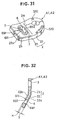
- a belt mounting clamp A1 to be manufactured is constructed as shown in Figs. 31 to 32, and has a construction substantially similar to that of the first example previously illustrated in Figs. 1 to 5 or that of the third example previously shown in Fig. 7. Accordingly, components common to those of the first example shown in Figs 1 to 5 and the third example shown in Fig. 7 are affixed with the same reference symbols and the explanation thereof will be simplified.
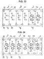
- the belt mounting clamp A1 is manufactured by a complete set of press machine which automatically and continuously carrying out the operations of respective steps illustrated in Figs. 33 to 36.
- a steel plate S wound like a coil which is a raw material of a base 2 is continuously fed to the press machine while it is restored to be flat.
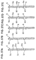
- the preliminary holes S1 of slots 6 are first punched out from the steel plate S and positioning holes H1 are punched out in a piercing step P1 (see Fig. 33).
- burs S1a are formed on one surface Sa side of the steel plate S owing to the punching-out of the preliminary holes S1.
- the burs S1a produced in the piercing step P1 are pressed and removed by a surface-pressing in a surface-pressing step P2 (see Fig. 33).
- a surface-pressing step P2 see Fig. 33.
- the steel plate is in a clear state in which the burs S1a are removed.
- the slot 6 is respectively formed by pushing a punch larger than the preliminary hole S1 into the preliminary slot S1 in a next burring step P3 (see Fig. 33) and a protrusion 611 is formed by projecting a part of the steel plate S along the slot 6.
- the protrusions 611 protruding from the other surface Sb of the steel plate S. In this case, however, the protrusions under this state have their corner parts left as they are.
- the protrusions 611 formed in the burring step P3 are respectively surface-pressed and their corner parts are rounded in a curved-surface forming step P4 (see Fig.34).
- the corner parts of the protrusions 611 are rounded.
- Edges 6a opposite to the protrusions 611 in the slots 6 are surface-pressed in a restriking step P5 so that the edge parts 6a are formed in a curved surface with larger radius of curvature. That is, the edge parts 6a are formed as illustrated in Fig. 37E.
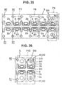
- the corner parts of the part cut in the cutting and stamping step P6 are slantingly surface-pressed so that C-shaped chamfered parts 2b are formed in a C surface-pressing step P7 (see Fig. 35).
- a bent part 2a is respectively formed on the steel plate S.
- a part is cut in a separating step P10 (see Fig. 36) so that it is continuous to the part cut in the cutting and stamping step P6, and that part is separated as a belt mounting clamp A1 with a prescribed configuration. Namely, the belt mounting clamp A1 displayed in Figs. 31 and 32 is completed.
- the protrusion 611 can be clearly projected in the burring step P3, and the corner parts of the protrusion 611 are clearly formed in a curved surface shape in the curved-surface forming step P4. Further, the edge part 6a opposite to the protrusion 611 in the slot 6 can be smoothly rounded with larger radius of curvature owing to the restriking step P5. Accordingly, since the corner parts in the slot 6 can be finished to be rounded only by the press machine, a finish working (barrel finish working) or a coating work does not need to be done in another step. Therefore, cost can be reduced.
- the belt mounting clamps A1 as single bodies are automatically and continuously completed. Therefore, the belt mounting clamps A1 can be continuously and efficiently manufactured.
- the protrusion 611 is formed by projecting a part of the steel plate S based on the burring work, it can be largely projected from the base 2.
- the protrusion 611 can be formed so that the amount of protrusion H of this protrusion 611 ranges from 15% to 60% as thick as the thickness T of the base 2, as can be seen in Fig. 32. Therefore, while the contact area of the belt with the belt mounting clamp can be increased, surface pressure exerted upon the belt can be decreased.
- One protrusion 611a and the other protrusion 611b can be formed which respectively protrude from the one surface 22a and the other surface 22b of the base 2 by carrying out the method shown in the third example illustrated in Figs 7 to 22, in addition to the burring step P3.
- the amount of protrusion H of the respective protrusions 611a and 611b which are formed in this case can also range from 15% to 60% as thick 5 as the thickness T of the base 2, as shown in Fig. 32.
- the respective protrusion 611, 611a and 611b can be formed, as illustrated in Fig. 32, so that the amount of protrusion H of them ranges from 15% to 60% as thick as the thickness T of the base 2.
- the belt mounting clamps A1 and A2 shown in the three embodiments of the present invention shown in Figs. 28 to 30 can be also manufactured by employing the manufacturing method of the fourth example shown in Figs. 31 to 37, or the method shown in Figs. 12 to 14 in addition to the above method.
- the respective protrusions 611, 611a and 611b can be formed so that the amount of protrusion H of them ranges from. 15% to 60% as thick as the thickness T of the base 2.
- the reasons why the amount of protrusion H is set to 15% to 60% as thick as the thickness T of the base, as mentioned above, are that when the amount of protrusion H is less than 15% as thick as the thickness T, desired effects can not be obtained, and when the amount of protrusion H exceeds 60% as thick as the thickness T, not only the cost necessary for forming the protrusion is significantly increased but also cracks may be undesirably generated in the protrusion during forming the protrusion.
- the amount of protrusion H is preferably located within a range of 20% to 50% of the thickness T of the base.
- the part of the belt which is reflected in one long edge part is tightly fixed to that one long edge part.
- the part of the belt which is folded back takes a configuration in which its central part in its lateral direction expands similarly to the one long edge part.
- the belt hardly slides laterally along the one long edge part. Therefore, even if the direction of the tension of the belt does not coincides with the direction perpendicular to the one long edge part, the belt will not slide sideward along the one long edge part so that it does not gather to the end part of the belt.
- the belt since the central part of the belt in its lateral direction swells similarly to that of the one long edge part, the belt is always brought into a state in which it is expanded in its lateral direction. Accordingly, even when the belt itself tends to thinly converge upon exertion of tension on the belt, the width of the belt is maintained in an original state in the one of the long edges. That is, the belt does not gather at one part on the one long edge part.
- the one long edge part expands in the direction opposite to the tension, even when the one long edge part is slightly elastically deformed toward the direction of tension, this one long edge part is not recessed depending on the tension of the belt. Thus, the belt does not come together to the recessed part of the one long edge part either.
- the width of the belt is properly maintained in the one long edge part, the tension of the belt is evenly transmitted to the one long edge part. Consequently, the durability of the belt and the belt mounting clamp can be improved and safety can be improved owing to the improvement of their durability.
- the belt is preferably curved so as to be folded along the central line in its longitudinal direction in order to maintain the flattened shape of the belt. Also when the belt is inserted into the slot while it is curved in such a manner, both the end parts at the right and left sides of the belt hardly strike against both the end parts of the one long edge parts, since the central part of the one long edge part is so formed as to swell and the curved shape of the belt substantially coincides with the shape of one long edge part. Additionally rounded and expanded parts at both the ends of the belt also hardly strike against the one long edge part. Therefore, the belt can be easily inserted into the slot.
- the configuration of the one or the other long edge part substantially correspond to that of the belt curved as stated above.
- the belt can be more easily inserted into the slot than in the case mentioned above.
- the belt seat mounting clamp since short edge parts through which the one long edge part is connected to the other long edge part are formed in curved shapes of circular arc which are smoothly continued from one and the other long edge parts, the rounded and expanded parts at both the ends of the belt hardly collide with the short edge parts.
- the belt can be advantageously more readily inserted into the slot.
- the one long edge part has a protrusion which protrudes from one surface side of the plate shaped member, the contact surface area of the belt abutting against the one long edge part is increased. As a result, the surface pressure of the belt can be reduced. Further, since the corner parts of the one long edge part are rounded along the direction in which the belt is folded back, the belt is prevented from breaking in the corner parts. Furthermore, since the corner parts are rounded and these corner parts do not need to undergo a coating work with vinyl chloride or polyethylene or the like, cost required for such a coating work can be reduced. That is, the cost can be lowered.
- the protrusion can be projected greatly from the other surface side. Therefore, the area of the belt abutting against the one long edge part can be increased. In other words, surface pressure exerted on the belt from the one long edge part can be completely lowered. Therefore, the durability of the belt and the strength of the belt mounting clamp can be improved, and safety can be improved based on the improvement of their durability and strength.
- the corner parts of the one long edge part are rounded long the direction in which the belt is folded back due to the existence of the protrusion, the belt can be prevented from being broken in these corner parts. Additionally, since the corner parts are rounded and do not need to be subjected to a coating work with vinyl chloride or polyethylene or the like, cost necessary for such a coating work can be reduced. Namely, the cost can be lowered.
- the one long edge part is formed so as to have one protrusion and the other protrusion which respectively protrude from one surface side and the other surface side of the plate shaped member, the contact surface area of the belt which abuts against the one long edge part is increased. As a result, the surface pressure of the belt can be further reduced.
- the one long edge part is formed so as to have one protrusion and the other protrusion which respectively protrude from one surface side and the other surface side by bending a part of the plate shaped member from the one surface side to the other surface side of the plate shaped member and pressing the bent part to return to the one surface side, the area of a part against which the belt abuts can be increased. Consequently, the surface pressure of the folded-back part of the belt can be furthermore reduced.
- the short edge parts are also provided with a protrusion, so that the strength of the short edge parts can be increased. Therefore, even if the belt is gathered to the short edge part so that force is concentrated to the short edge part, the safety of the short edge part can be more improved than the past until the present.
- the strength of an entire part around the slot can be improved.
- the short edges are formed to be curved in a circular arc shape, the concentration of stress to the short edge parts can be relieved.
- the contact surface area the belt which abuts against the one long edge part can be increased owing to the presence of the protrusion.
- the surface pressure of the belt can be reduced.
- the protrusions are formed so as to protrude from both the one surface side and the other surface side of the plate member, the surface pressure of the belt can be most reduced.
- the corner parts of the one long edge part are rounded along the direction in which the belt is folded back, the belt can be prevented from being broken in these corner parts. Further, since the corner parts are rounded and they do not need to undergo a coating work with vinyl chloride or polyethylene or the like, expenses required for such a coating work can be reduced. That is the cost can be lowered.
- the amount of protrusion of the respective protrusions which are projected from the plate shaped member ranges from 20% to 60% as thick as the thickness of the plate shaped member, so that the contact surface area of the belt which abuts against the one long edge part can be increased.
- a magnification as 20% to 60% is enabled by forming part of the slot by a bending work, or forming it by a burring work.
- the protrusion can be clearly projected in a burring step and the corner parts of the protrusion can be finely formed in a curved-surface forming step.
- the edge part opposite to the protrusion in the slot can be smoothly rounded with a larger radius of curvature in a restriking step. Therefore, since the corner parts can be finished so as to be rounded in a series of press working steps for forming the belt mounting clamp, a finishing work or a coating work must not be carried out in another step. Accordingly, the cost can be reduced.
Abstract

Description
- The present invention relates to a seat belt anchorage plate formed by a belt mounting clamp for a seat belt device for attaching the end of, for example, a seat belt for an automobile to a fixed part such as a vehicle body.
- The present invention also relates to a method for manufacturing such a seat belt anchorage plate.
- Conventionally, as such kind of belt mounting clamp, a clamp illustrated in Fig. 38 has been well known. That is, a belt mounting clamp comprises a base (plate shaped member) 2 having a
bolt hole 3 and aslot 69 formed thereon and is designed to be secured to a fixed part such as a vehicle body through thebelt hole 3 and to be connected to abelt 13 through theslot 69. - The
belt 13 employs a thin band shaped woven fabric in which for example, polyester fibers are woven and is folded back in onelong edge part 691 of theslot 69, so that tension is exerted on the onelong edge part 691 which is linearly formed. - Since the above mentioned conventional belt mounting clamp has one
long edge part 691 formed in a straight line, when the tension of thebelt 13 is not exerted in the direction perpendicular to the onelong edge part 691, thebelt 13 is liable to laterally slide on the onelong edge part 691 and come together to the end part of thelong edge part 691. In other words, there has been encountered a problem that the belt is apt to be gathered to the end part of onelong edge part 691. Even if the tension of thebelt 13 is exerted in the direction perpendicular to the onelong edge part 691, for example, according to an examination through a strength measuring test, thebelt 13 itself will be thinly converged and tend to meet at one part on the onelong edge part 691 when the tension is exerted on thebelt 13. Further, since the onelong edge part 691 is elastically bent and slightly recessed by virtue of the tension of thebelt 13, thebelt 13 is undesirably liable to be gathered to one part on thelong edge part 691 in addition to the defect that thebelt 13 itself thinly converges into one part. - Further, the
belt 13 is advantageously curved so as to be folded along a center line in its longitudinal direction in order to maintain the flat state of thebelt 13. Therefore, thebelt 13 is normally inserted into theslot 69 under its curved state as stated above. However, when thebelt 13 is curved in such a way, there arises a problem that both ends at the right and left sides of thebelt 13 abut against, for example, both right and left ends of the onelong edge part 691, and therefore, thebelt 13 is inserted into theslot 69 with difficulty. As shown in Fig.38, when both the end parts of thebelt 13 swell out roundly, there also arises a problem that these swelling parts tend to more easily abut against both the end parts of onelong edge part 691. - Still further, the
slot 69 is formed by a press working. In this case, burs are liable to be formed at the corner parts in the side punched out by a press. When such burs are left as they are, they have possibility to cause an action similar to that of a cutter. Accordingly, the corner parts are ordinarily subjected to a rounding finish independent of a press working process, or a coating work to cover the entire corner parts with vinyl chloride or polyethylene or the like. As a result, a problem has been encountered in terms of cost-up owing to such a finishing work or a coating work. - Additionally stated, as illustrated in Fig. 39, since a belt mounting clamp is formed with a plate shaped
base 2, the area of onelong edge part 691 for holding thebelt 13 is small, so that surface pressure exerting on thebelt 13 is disadvantageously increased. - The present invention was made by taking these problems into account and an object of the present invention is to provide a seat belt anchorage plate forming a belt mounting clamp for a seat belt device capable of completely reducing surface pressure to be exerted on the belt even when tension acts on the belt.
- In order to achieve the above described object, it is proposed, according to the invention, the seat belt anchorage plate as defined in
claims 1 to 6. - Another object is to provide a method of manufacturing such a seat belt anchorage plate. Such an object is achieved through the method defined in
claims 7 to 12. - Such a seat belt anchorage plate can serve as a belt mounting clamp for a seat belt device which is formed with a plate shaped member, the plate shaped member having a slot formed into which the belt is inserted; the slot having long edge parts opposed to each other one of which bears the tension of the belt folded back therein.
- In a first embodiment, since the one long edge part has a protrusion which protrudes from one surface side of the plate shaped member, the contact surface area of the belt abutting against the one long edge part is increased. As a result, the surface pressure of the belt can be reduced. Further, since the corner parts of the one long edge part are rounded along the direction in which the belt is folded back, the belt is prevented from breaking in the corner parts. Furthermore, since the corner parts are rounded and these corner parts do not need to undergo a coating work with vinyl chloride or polyethylene or the like, the cost required for such a coating work can be reduced. That is, the cost can be lowered.
- In a variant of the first embodiment, since a protrusion which protrudes from the other surface of the plate shaped member is formed by bending a part of the plate shaped member from the one surface side to the other surface side of the plate shaped member, the protrusion can be projected greatly from the other surface side. Therefore, the area of the belt abutting against the one long edge part can be increased. In other words, surface pressure exerted on the belt from the one long edge part can be completely lowered. Therefore, the durability of the belt and the strength of the belt mounting clamp can be improved, and safety can be improved based on the improvement of their durability and strength. Further, since the corner parts of the one long edge part are rounded, the belt can be prevented from being broken in these corner parts. Additionally, since the corner parts are rounded and do not need to be subjected to a coating work with vinyl chloride or polyethylene or the like, the cost necessary for such a coating work can be reduced. Namely, the cost can be lowered.
- Since the one long edge part is formed so as to have one protrusion and the other protrusion which respectively protrude from one surface side and the other surface side of the plate shaped member, the contact surface area of the belt which abuts against the one long edge part is increased. As a result, the surface pressure of the belt can be further reduced.
- Since the one long edge part is formed so as to have one protrusion and the other protrusion which respectively protrude from one surface side and the other surface side by bending a part of the plate shaped member from the one surface side to the other surface side of the plate shaped member and pressing the bent part to return to surface side, the area of a part against which the belt abuts can be increased. Consequently, the surface pressure of the folded-back part of the belt can be furthermore reduced.
- According to a second embodiment, the short edge parts are also provided with a protrusion, so that the strength of the short edge parts can be increased. Therefore, even if the belt is gathered to the short edge part so that force is concentrated to the short edge part, the safety of the short edge part can be more improved than the past until the present. In addition, where a whole edge part except the one long edge part is also provided with a protrusion, the strength of an entire part around the slot can be improved.
- Since the operational advantages as mentioned above can be exhibited, and the short edges are formed to be curved in a circular arc shape, the concentration of stress to the short edge parts can be relieved.
- According to the above mentioned first and second embodiments, the contact surface area the belt which abuts against the one long edge part can be increased owing to the presence of the protrusion. As a result, the surface pressure of the belt can be reduced. According to the variant where the protrusions are formed so as to protrude from both the one surface side and the other surface side of the plate member, the surface pressure of the belt can be most reduced.
- Since the corner parts of the one long edge part are rounded along the direction in which the belt is folded back, the belt can be prevented from being broken in these corner parts. Further, since the corner parts are rounded and they do not need to undergo a coating work with vinyl chloride or polyethylene or the like, expenses required for such a coating work can be reduced. That is, the cost can be lowered.
- The invention will be now be described further, by way of example, with reference to the accompanying drawings, in which :
- Fig. 1 is a front view of an example of a belt mounting clamp which is not part of the present invention ;
- Fig. 2 is a sectional view of the belt mounting clamp taken along a line ll-ll in Fig. 1 ;
- Fig. 3 is an enlarged view of the belt mounting clamp in a part lll shown in Fig. 2 ;
- Fig. 4 is a sectional view of the belt mounting clamp taken along a line IV-IV in Fig. 1 ;
- Fig. 5 is an explanatory view illustrating in the using state of the belt mounting clamp in an automobile ;
- Figs. 6A, 6B, 6C and 6D are sectional views of a second example of a belt mounting clamp forming a seat belt anchorage plate which is not part of the present invention ;
- Fig. 7 is a perspective view of a belt mounting clamp shown as a third example which is not part of the present invention ;
- Fig. 8 is an explanatory view showing a first manufacturing step when the belt mounting clamp is manufactured ;
- Fig. 9 is an explanatory view showing a second manufacturing step when the belt mounting clamp is manufactured ;
- Fig. 10 is an explanatory view showing a third manufacturing step when the belt mounting clamp is manufactured ;
- Fig. 11 is an explanatory view showing a fourth manufacturing step when the belt mounting clamp is manufactured ;
- Fig. 12 is an explanatory view showing a fifth manufacturing step when the belt mounting clamp is manufactured ;
- Fig. 13 is an explanatory view showing a sixth manufacturing step when the belt mounting clamp is manufactured ;
- Fig. 14 is an explanatory view showing a seventh manufacturing step when the belt mounting clamp is manufactured ;
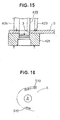
- Fig. 15 is an explanatory view showing an eighth manufacturing step when the belt mounting clamp is manufactured ;
- Fig. 16 is an explanatory view showing the shape of the belt mounting clamp after the eighth manufacturing step ;
- Fig. 17 is an explanatory view showing a ninth manufacturing step when the belt mounting clamp is manufactured ;
- Fig. 18 is an explanatory view showing the shape of the belt mounting clamp after the ninth manufacturing step ;
- Fig. 19 is an explanatory view showing a tenth manufacturing step when the belt mounting clamp is manufactured ;
- Fig. 20 is an explanatory view showing the shape of the belt mounting clamp after the tenth manufacturing step;
- Fig. 21 is an explanatory view showing an eleventh manufacturing step when the belt mounting clamp is manufactured ;
- Fig. 22 is an explanatory view showing the shape of the belt mounting clamp after the eleventh manufacturing step ;
- Fig. 23 is an explanatory view showing a fifth manufacturing step when manufacturing a belt mounting clamp which is illustrated as an alternative form of the third example ;
- Fig. 24 is an explanatory view showing a sixth manufacturing step when the belt mounting clamp is manufactured ;
- Fig. 25 is an explanatory view showing a seventh manufacturing step when the belt mounting clamp is manufactured ;
- Fig. 26 is a front view of a belt mounting clamp illustrated as an alternative example of the previously illustrated examples ;
- Fig. 27 is a front view of a belt mounting clamp illustrated as an alternative of the previously illustrated examples ;
- Fig. 28 is a view of a belt mounting clamp illustrated as a first embodiment of the present invention; Fig. 28A is a front view; Fig. 28B is a sectional view, and Fig. 28C is a sectional view showing an alternative example of Fig. 28B ;
- Fig. 29 is a view of a belt mounting clamp illustrated as a second embodiment of the present invention; Fig. 29A is a front view; Fig. 29B is a sectional view, and Fig. 29C is a sectional view showing an alternative example of Fig. 29B ;
- Fig. 30 is a view of a belt mounting clamp illustrated as a third embodiment of the present invention; Fig. 30A is a front view; Fig. 30B is a sectional view, and Fig. 30C is a sectional view showing an alternative example of Fig. 30B;
- Fig. 31 is a perspective view of a belt mounting clamp manufactured by a manufacturing method illustrated as a fourth example which is not part of the present invention ;
- Fig. 32 is a sectional view of the belt mounting clamp manufactured by this manufacturing method ;
- Fig. 33 is a plan view of a steel plate illustrating respective steps including a piercing step P1 to a burring step P3 in this manufacturing method ;
- Fig. 34 is a plan view of a steel plate illustrating respective steps including a curved-surface forming step P4 to a cutting and stamping step P6 in the above stated manufacturing method ;
- Fig. 35 is a plan view of a steel plate illustrating respective steps including a C surface-pressing step P7 to a piercing step P9 ;
- Fig. 36 is a plan view of a steel plate illustrating a separating step P10 in the above stated manufacturing method ;
- Fig. 37 shows sectional views of the steel plates in this manufacturing method, Fig. 37A is a sectional view of the steel plate in the piercing step P1, Fig. 37B is a sectional view of the steel plate in the surface-pressing step P2, Fig. 37C is a sectional view of the steel plate in the burring step P3, Fig. 37D Is a sectional view of the steel plate in the curved-surface forming step P4 and Fig. 37E is a sectional view of the steel plate in a restriking step P5 ;
- Fig. 38 is a front view of a belt mounting clamp illustrated as a conventional example ; and
- Fig. 39 is a sectional view of this belt mounting clamp.
-
- Embodiments of a seat belt anchorage plate will be described hereinbelow with reference to Figs. 1 to 37. Initially, referring to Figs. 1 to 5, a first example of a seat belt anchorage plate will be described below, which is not part of the present invention.
- In Fig. 5, S designates the vehicle body of an automobile, D a driver's seat, and 1 a seat belt device. A
retractor 11 for a shoulder belt is fixed to the vehicle body S.A shoulder belt 12 is connected to thisretractor 11. A belt mounting clamp A1 is fixed to one side of the seat D in the vehicle body S.A waist belt 13 is connected to this belt mounting clamp A1. Theseshoulder belt 12 andwaist belt 13 are formed with one belt, which is divided into theshoulder belt 12 in theretractor 11 side and thewaist belt 13 in the belt mounting clamp A1 side by sandwiching atongue clamp 14 therebetween as a border. - The above described
tongue clamp 14 is detachably connected to abuckle 15 which is connected to another belt mounting clamp A2 through a connectingbelt 151. This belt mounting clamp A2 is fixed to the vehicle body S opposite to that of the belt mounting clamp A1 by sandwiching the seat D therebetween. Since these belt mounting clamps A1 and A2 have substantially the same construction, the construction of the belt mounting clamp A1 will be specifically described using its reference symbols. - The belt mounting clamp A1 forms a seat belt anchorage plate and is made of a plate shaped base (plate shaped member) 2, and slightly bent at a bending
part 2a to be formed in a "<" shape, as illustrated in Figs. 1 to 2. The plate shapedbase 2 is constituted of a fixingplate part 21 in one side and a belt windingplate part 22 in the other side which sandwich this bendingpart 2a therebetween as a border. In the fixingplate part 21, abolt hole 3 is formed. A plurality ofcurved protrusions 31 are formed at equal intervals in the radial direction of the peripheral edge part of the bolt hole 3 (in the illustrated example, three protrusions are formed). The respectivecurved protrusions 31 are projected from the one surface side to the other surface side of thebase 2 by a press working. The number of the curved protrusions is not limited and the protrusions may be finely radially provided like a chrysanthemum seat. - As shown in Fig.2, a fixing
bolt 5 is inserted into thebolt hole 3. Thebase 2 is designed to be fixed to the vehicle body S by means of thisbolt 5 and anut 51. At this time, the above statedcurved protrusions 31 serve as means similar to a spring washer as well as locking means for stopping rotation due to the increase of friction. Thus, the curved protrusions are useful for assuredly fixing thebase 2 to the vehicle body S. Further, the spring washer which bas been conventionally usually employed does not need to be used. Therefore, the number of parts required can be reduced. - On the other hand, a
slot 6 for inserting and connecting one end part of thewaist belt 13 is formed on the belt windingplate part 22 of thebase 2. Thewaist belt 13 is folded back in onelong edge part 691 of theslot 6 so that tension is exerted on the onelong edge part 691. The onelong edge part 691 bearing the tension is curved at a central part in its longitudinal direction so as to protrude in the direction opposite to that on which the tension is exerted. Thewaist belt 13 employs a belt similar to one shown in the conventional example, a band shaped and flattened thin woven fabric into which polyester fibers are woven. One end part of thebelt 13 in its longitudinal direction is folded back in the onelong edge part 691. The folded-back part is sewn onto thewaist belt 13 so that it is fixed to thebase 2. - Further, the other
long edge part 692 opposed to the onelong edge part 691 is also curved in the direction similar to that of the onelong edge part 691. Parts through which the one long edge part is connected to the otherlong edge part 692 areshort edge parts - The
slot 6 comprising one and the otherlong edge parts short edge parts slot 6 has a circular arc shapedinner surface 61 formed from onesurface 22a side of thebase 2 to the interior of theslot 6 and aprotrusion 611 protruding in a circular arc shape which is formed from the interior of theslot 6 to theother surface 22b side. Theseinner surface 61 andprotrusion 611 are formed by press-working. - In the belt mounting clamp for a seat belt device constructed as mentioned above, since the central part of the one
long edge part 691 is curved so as to protrude in the direction opposite to the tension of thewaist belt 13, even when the onelong edge part 691 is elastically deformed in the direction of the tension, thelong edge part 691 is not deformed in a recessed shape in the direction of tension. Thus, the belt does not gather to the recessed part and the width of thewaist belt 13 is usually maintained to a normal width. Consequently, since the tension of thebelt 13 is constantly uniformly distributed on the onelong edge part 691, the strength performance of thewaist belt 13 and the belt mounting clamp A1 and safety can be improved depending on the improvement of their strength. - Further, since the other
long edge part 692 is also curved in a similar way to the onelong edge part 691, when thewaist belt 13 is inserted into theslot 6 while it is curved so as to be folded back along a central line in its longitudinal direction in order to maintain the flat state of thewaist belt 13, the configurations of the one and the otherlong edge parts waist belt 13. Thus, thewaist belt 13 can be extremely easily inserted into theslot 6. - Since the connecting parts of the one and the other
long edge parts short edge parts waist belt 13 along its 5 longitudinal direction are expanded in a circular arc shape, the expanded parts do not collide with theshort edge parts waist belt 13 can be advantageously readily inserted into theslot 6. In addition, both the end parts of thewaist belt 13 can fit in theshort edge parts waist belt 13, thebelt 13 can be stably held in its prescribed position of theslot 6. - Further, the
slot 6 has a circular arc shapedinner surface 61 from the onesurface 22a side of thebase 2 to the interior of theslot 6 and aprotrusion 611 protruding in a circular arc shape from the interior of theslot 6 to theother surface 22b side. Therefore, such a possibility can be removed that thewaist belt 13 folded back in the onelong edge part 691 collides with the corner parts and then is cut. Additionally, since an area of thewaist belt 13 which abuts against the onelong edge part 691 is increased due to the existence of theprotrusion 611, surface pressure exerted on thewaist belt 13 can be decreased and the durability and reliability of thewaist belt 13 can be improved. - Still further, since the
protrusion 611 is formed on the entire periphery of theslot 6, strength in the periphery of the slot is improved and the strength of the whole belt mounting clamp A1 can be improved. Particularly, since theshort edge parts 7 can be strengthened, even if the end part of thewaist belt 13 gather to theshort edge part 7 and force is concentrated on theshort edge part 7, the safety of the short edge part can be improved more than before. - In addition to the above, when tension is exerted upon the
waist belt 13, thewaist belt 13 folded back in the onelong edge part 691 comes into tight contact with the onelong edge part 691. More specifically stated, the folded back part of thewaist belt 13 is curved in a configuration similar to that of the onelong edge part 691 and the central part of the belt in its lateral direction expands. Therefore, thewaist belt 13 hardly slides in its lateral direction along the onelong edge part 691. Accordingly, even when the direction of the tension of thewaist belt 13 does not coincide with the direction perpendicular to the onelong edge part 691, thewaist belt 13 does not slide sideward along the onelong edge part 691 nor gather to the end part of theslot 6. - Further, since the central part of the
waist belt 13 in the direction of its width swells in a similar manner to the onelong edge part 691, thewaist belt 13 is always expanded in its lateral direction. Accordingly, even when thewaist belt 13 itself tends to thinly converge upon exertion of tension on thewaist belt 13, thewaist belt 13 is maintained in its original expanded state on the onelong edge part 691. That is, thewaist belt 13 does not gather to one part on the onelong edge part 691. As mentioned above, since the width of the belt folded back part is appropriately maintained, the tension of the belt is uniformly transmitted to the one long edge part. Consequently, not only the durability of the belt and the strength performance of the belt mounting clamp but also safety can be improved. - In the next place, referring to Figs. 6A to 6D, a second example which is not part of the present invention will be described. While the second example is different from the first example in that the shapes of the
respective slots 6 are different from each other, the second example is similar to the first example in terms of other points. Therefore, the explanation therefor will be omitted. - Specifically, in the case of a
slot 6 comprising one and the otherlong edge parts short edge parts slot 6 is formed in a recessed shape by a plurality of times of press-workings, as illustrated in Figs. 6A, 6B, and 6C. Then, the bottom of the recessed part is punched out to be removed so that a protrudingpiece 23 which protrudes from onesurface 22a side of abase 2 to theother surface 22b side is formed. At this time, a curved surface R1 is formed which is curved in a circular arc shape from the onesurface 22a to the inner surface of the protrudingpiece 23. As can be seen in Fig. 6D, the end part of the protrudingpiece 23 is folded back by a press-working (curling work) so that it further comes near theother surface 22b. Thus, aprotrusion 611 which largely protrudes to theother surface 22b side is formed and a curved surface R2 is formed which is smoothly curled from the inner surface of theslot 6 to theprotrusion 611. - In a belt mounting clamp for a seat belt device constructed as described above, since the
base 2 is subjected to a drawing work so that theslot 6 is formed, the height of theprotrusion 611 is particularly increased and an area of onelong edge part 691 against which awaist belt 13 abuts is larger than that of the first example. Consequently, surface pressure exerted on thewaist belt 13 is decreased and the durability of thewaist belt 13 and safety can be furthermore improved. In addition, since the curved surfaces R1 and R2 are configured respectively in the corner parts of the onelong edge part 691 in which thewaist belt 13 is folded back. Therefore, no possibility may arise that thewaist belt 13 is worn an torn on the onelong edge part 691. Other operational effects exhibited in the second example are similar to those of the first example. - Now, a third example which is not part of the present invention will be described with reference to Figs. 7 to 22. Components similar to those in the first example shown in Figs. 1 to 5 are affixed with the same reference symbols, however, the explanation therefor will be simplified.
- A belt mounting clamp A1, as illustrated in Fig. 7, is bent substantially at right angles with a belt winding
plate part 22 in abent part 2a. Aslot 6 is formed on the belt windingplate part 22. Thisslot 6 is provided with oneprotrusion 611a and theother protrusion 611b which respectively protrude to onesurface 22a side and theother surface 22b side. In other words, theslot 6 has an inner surface whose length is increased due to the oneprotrusion 611a and theother protrusion 611b, so that the area of alongedge part 691 against which awaist belt 13 abuts is increased. - Further, the one
protrusion 611a and theother protrusion 611b are respectively projected to the onesurface 22a side and theother surface 22b side in such a manner that a protrusion protruding from theother surface 22b is formed by bending (burring) a part of thebase 2 from the onesurface 22a side of thebase 2 to theother surface 22b side and moving this protrusion to the onesurface 22a side by a press. Consequently, the amount of protrusion of the oneprotrusion 611a and theother protrusion 611b are respectively determined based on the amount of initial bending (amount of protruding) of thebase 2. Therespective protrusions long edge part 691, its corner parts are rounded along the direction in which thewaist belt 13 is folded back. In addition, C chamferedparts 2b are formed on the end parts of the outer periphery of thebase 2. A marking S10 is stamped on the periphery of abolt hole 3 on thebase 2. - In the belt mounting clamp A1 constructed as stated above, since the amount of respective protrusions of the one
protrusion 611 a and theother protrusion 611b can be increased depending on the amount of bending (amount of protruding) of thebase 2, the area of a part in the onelong edge part 691 against which thewaist belt 13 abuts can be increased up to a satisfactory value as required. Therefore, surface pressure exerted upon thewaist belt 13 from the onelong edge part 691 can be completely lowered and safety can be improved depending on the improvement of the durability of thewaist belt 13 and the strength performance of the belt mounting clamp A1. - Still further, since the one
protrusion 611 a and theother protrusion 611b are formed to be rounded and the corner parts of the protrusions are rounded along the direction in which thewaist belt 13 is folded back on thelong edge part 691, thewaist belt 13 can be prevented from being broken on the protrusions. Besides, since the corner parts of the protrusions are rounded and the protrusions do not need to undergo a coating work with vinyl chloride or polyethylene or the like, expenses necessary for such a coating work can be reduced, namely, the cost can be reduced. - Next, a method for manufacturing the belt mounting clamp A1 composed as stated above will be described below.
- Initially, as a first step illustrated in Fig. 8, a first lower hole S1 for forming a
slot 6 is bored on a steel plate S as the raw material of abase 2 using a metal mold K1 and a punch K2. Then, in a second step as illustrated in Fig. 9, a circular arc shaped roundness S1a is formed from the upper part of the first preliminary hole S1 to the upper surface of the steel plate S, using a metal mold K3 and a metal mold K4. Further, In a third step as shown in Fig. 10, a circular arc shaped roundness S1b is formed from the lower part of the first preliminary hole S1 to the lower surface of the steel plate S, using a metal mold K5 and a metal mold K6. - In the next place, in a fourth step illustrated in Fig. 11, the part of the first preliminary hole S1 is curved above the steel plate S (burring work), using a metal mold K7 and a metal mold K8 so that a second preliminary hole S2 is formed. Then, in a fifth step as illustrated in Fig. 12, the part of the second preliminary hole S2 which protrudes upward is surface-pressed downward by using a metal mold K9, a metal mold K10 and a metal mold K11 so that a protrusion S3 and a protrusion S4 are formed which protrude with substantially the same height from the upper and lower surfaces of the steel plate S.
- Further, in a sixth step as shown in Fig. 13, the protrusion S3 which protrudes toward the upper side is finished by using a metal mold K12 and a metal mold K13 so as to have an entirely smooth curved surface (restriking work). At this time, the surface of the second preliminary hole S2 is finely finished. Then, in a seventh step as shown in Fig. 14, the protrusion S4 which protrudes toward the lower side is finished by using a metal mold K14 and a metal mold K15 so as to have an entirely smooth curved surface (restriking work). At this time, the surface of the second preliminary hole S2 is also finely finished. Thus, a
slot 6 is formed with the second preliminary hole S2 finished in such a way and oneprotrusion 611a and theother protrusion 611a are formed with the protrusions S3 and S4. - Next, in an eighth step shown in Fig. 15, a
bolt hole 3 is bored on the steel plate S and markings are stamped on the periphery of thebolt hole 3 by using a metal mold K21, a punch K22 and marking presses K23 and K24. Thus, as illustrated in Fig. 16, a product is in a state in which thebolt hole 3 is bored and the markings S10 are stamped. Further, in a ninth step as shown in Fig. 17, the outer periphery of a belt mounting clamp is cut (trimming work) by using a metal mold K25,metal molds K 26 and metal molds K27. At this time, since the cut part of the steel plate S enters the metal molds K27, it is pushed out to be ejected by an ejector 28. In this way, a product with a configuration similar to the belt mounting clamp shown in Fig. 18 is obtained. Then, in a tenth step as illustrated In Fig. 19, a C-shape chamferedpart 2b is formed by using a metal mold K29 and a metal mold K30. Thus, the C-shape chamferedpart 2b is formed on the belt mounting clamp as can be seen in Fig. 20. Then, in an eleventh step as illustrated in Fig. 21, the steel plate S which forms a belt mounting clamp is bent substantially at right angles with the rest of the steel plate S along abent part 2a by employing a metal mold K31 and a metal mold K32. Thus, a belt mounting clamp A1 as shown in Fig. 22 is completed. - As mentioned above, the belt mounting clamp A1 is formed with the steel plate S by press-workings. Although the manufacturing method of the belt mounting clamp has been divided into the eleven steps and these steps have been individually explained according to the above description, this manufacturing method is actually divided into still more steps so that the material is gradually deformed until the belt mounting clamp is formed therewith.
- According to the above described third example, although the protrusions protrude on both the one
surface 22a and theother surface 22b side of thebase 2, the protrusion may only protrude either on onesurface 22a or on theother surface 22b. A method for forming the protrusion protruding only on one side may be achieved by carrying out fifth to seventh steps shown in Figs. 23 to 25 after the fourth step shown in Fig.11. - Specifically, after the part of the first lower hole S1 is curved above the steel plate S so that the second preliminary hole S2 is formed according to the fourth step illustrated in Fig. 11, in a fifth step as shown in Fig. 23, the part of the second preliminary hole S2 which protrudes to the upper side is surface-pressed to the lower side by using a metal mold K15 and a metal mold K16. Thus, a protrusion S3 is formed which protrudes with a substantially constant height from the upper surface of the steel plate S.
- Additionally stated, in a sixth step as illustrated in Fig. 24, an edge S5 opposite to the protrusion S3 protruding to the upper side is finished so as to have a smooth curved surface by employing a metal mold K17 and a metal mold K18. At this time, the surface of the second
preliminary hole 2 is also clearly finished. Then, in a seventh step as illustrated in Fig. 25, the protrusion S3 protruding to the upper side is subjected to a finishing work so as to have an entirely smooth curved surface by using a metal mold K19 and a metal mold K20. At this time, the surface of the second preliminary hole S2 is also finely cleaned. Thus, aslot 6 is formed with the second preliminary hole S2 finished in this way, and aprotrusion 611 protruding, for example, to theother surface 22b side of the belt mounting clamp A1 is formed with the protrusion S3. - While the constructions of the belt mounting clamp A1 and the
waist belt 13 have been described in detail in the above stated first to third examples, the constructions of a belt mounting clamp A2 and a connectingbelt 151 are same as those of the belt mounting clamp A1 and thewaist belt 13. Further, the belt is not limited to thewaist belt 13 or the connectingbelt 151, but may include ashoulder belt 12 or other belts. Still further, according to the respective examples mentioned above, although the belt is formed by flattening a tubular one, it should be noted that a belt simply formed in a flat plate shape is employed. - Still further, although the other
long edge part 692 has been curved in configuration in a similar way to the onelong edge part 691, the otherlong edge part 692 may be formed in a linear shape or other shape. In this case, the otherlong edge part 692 is preferably formed to be curved substantially similarly to the onelong edge part 691 so that the belt can be easily inserted into the slot. - In addition, although the
protrusion 611 has been formed entirely on theslot 6, it may be provided only on the onelong edge part 691, that is, a part against which thewaist belt 13 abuts. Further, although theshort edge parts 7 do not necessarily need to be configured in a circular arc shape, they are preferably formed in a curved circular arc shape so that thewaist belt 13 or the like is inserted into the slot and stress concentration exerted on these parts is mitigated. - Additionally, although the one or the other
long edge parts - Furthermore, although the one
long edge part 691 has its central part in its longitudinal direction curved to protrude in the direction opposite to the direction to which tension is applied, it is to be noted that this long edge part may be formed so as to expand, in the direction opposite to that of the tension of the belt, from its ends to its central part in its longitudinal direction. In other words, if the central part of the onelong edge part 691 in its longitudinal direction swells relative to both the ends thereof, the central part may be in a flattened state. - Now, referring to Fig. 28, a first embodiment of the present invention will be described below. In this case, components common to those of the first example illustrated in Figs. 1 to 5 are affixed with the same reference symbols and the explanation thereof will be simplified. The first embodiment of the present invention shown in Fig. 28 is different from the first example shown in Figs. 1-5 in that one
long edge part 691 and the otherlong edge part 692 in aslot 6 are formed linearly in its shape. - Specifically, the
slot 6 is formed in an elongated shape, as shown in Fig. 28A. Aprotrusion 611 is formed only on onelong edge part 691. Thisprotrusion 611 protrudes only on theother surface 22b side of abase 2 forming a seat belt anchorage plate, as illustrated in Fig. 28B. Theprotrusion 611 may be formed as oneprotrusion 611a and theother protrusion 611b to protrude respectively from onesurface 22a side and theother surface 22b from thebase 2, as shown in Fig. 28C. - With a belt mounting clamp A1 constructed as described above, operational effects as good as those of the first example shown in Figs. 1-5 can be attained, regarding the constructions of the
protrusion 611 or the oneprotrusion 611 a and theother protrusion 611b. - Now, referring to Fig. 29, a second embodiment of the present invention will be described below. Herein, components common to those of the first embodiment of the present invention are affixed with the same reference symbols and the explanation thereof will be simplified. The second embodiment shown in Figs. 29A - 29C is different from the first embodiment shown in Figs. 28A - 28C, in that a protrusion is formed on the parts of one
long edge part 691 and twoshort edge parts - In other words, the
protrusion 611 is formed, as illustrated in Fig. 29A, so as to wind about the onelong edge part 691 and the twoshort edge parts protrusion 611 protrudes only on theother surface 22b side of abase 2. Theprotrusion 611 may be formed, as can be seen in Fig. 29C, as oneprotrusion 611a and theother protrusion 611b to respectively protrude from onesurface 22a side and theother surface 22b side of thebase 2. - According to a belt mounting clamp A1 constructed as mentioned above, the
short edge parts protrusion 611 or the oneprotrusion 611a and theother protrusion 611b. Besides, operational effects as good as those of the first embodiment can be achieved. - Next, referring to Fig. 30, a third embodiment of a belt mounting clamp according to the present invention will be described in the following. Herein, common components to those of the first embodiment of the present invention shown in Fig. 28 are affixed with the same reference symbols and the explanation thereof will be simplified. The third embodiment of the present invention shown in Fig. 30 is different from the first embodiment shown in Fig. 28 in that a
protrusion 611 is formed on onelong edge part 691, the otherlong edge part 692 and twoshort edge parts - That is, as illustrated in Fig. 30A, the protrusion is formed on all the periphery of a
slot 6. As illustrated in Fig. 30B, thisprotrusion 611 is provided to protrude only on theother surface 22b side of abase 2. Further, thisprotrusion 611 may be provided as oneprotrusion 611a and theother protrusion 611b to respectively protrude from onesurface 22a and theother surface 22b of thebase 2, as can be seen in Fig. 30C. - According to a belt mounting clamp A1 constructed as stated above, the entire part of the
slot 6 can be strengthened due to the presence of theprotrusion 611 or the oneprotrusion 611a and theother protrusion 611b. In addition, with this belt mounting clamp A1, operational effects similar to those of the first embodiment of the present invention shown in Fig. 28 and the second embodiment of the present invention shown in Fig. 29 can be attained. - Now, with reference to Figs. 31 to 37, as a fourth example of a seat belt clamp, which is not part of the present invention, a method for manufacturing a belt mounting clamp will be described. A belt mounting clamp A1 to be manufactured is constructed as shown in Figs. 31 to 32, and has a construction substantially similar to that of the first example previously illustrated in Figs. 1 to 5 or that of the third example previously shown in Fig. 7. Accordingly, components common to those of the first example shown in Figs 1 to 5 and the third example shown in Fig. 7 are affixed with the same reference symbols and the explanation thereof will be simplified.
- The belt mounting clamp A1 is manufactured by a complete set of press machine which automatically and continuously carrying out the operations of respective steps illustrated in Figs. 33 to 36.
- Initially, a steel plate S wound like a coil which is a raw material of a
base 2 is continuously fed to the press machine while it is restored to be flat. - Then, the preliminary holes S1 of
slots 6 are first punched out from the steel plate S and positioning holes H1 are punched out in a piercing step P1 (see Fig. 33). At this time, as illustrated in Fig. 37A, burs S1a are formed on one surface Sa side of the steel plate S owing to the punching-out of the preliminary holes S1. - Then, the burs S1a produced in the piercing step P1 are pressed and removed by a surface-pressing in a surface-pressing step P2 (see Fig. 33). Thus, as shown in Fig. 37B, the steel plate is in a clear state in which the burs S1a are removed.
- Then, the
slot 6 is respectively formed by pushing a punch larger than the preliminary hole S1 into the preliminary slot S1 in a next burring step P3 (see Fig. 33) and aprotrusion 611 is formed by projecting a part of the steel plate S along theslot 6. Thus, as shown in Fig. 37C, theprotrusions 611 protruding from the other surface Sb of the steel plate S. In this case, however, the protrusions under this state have their corner parts left as they are. - Now, the
protrusions 611 formed in the burring step P3 are respectively surface-pressed and their corner parts are rounded in a curved-surface forming step P4 (see Fig.34). Thus, as shown in Fig. 37D, the corner parts of theprotrusions 611 are rounded. -
Edges 6a (see Fig. 37) opposite to theprotrusions 611 in theslots 6 are surface-pressed in a restriking step P5 so that theedge parts 6a are formed in a curved surface with larger radius of curvature. That is, theedge parts 6a are formed as illustrated in Fig. 37E. - Then, the circumference of a part necessary for a folding and bending work is cut and markings S10 are stamped at prescribed positions in a cutting and stamping step P6 (see Fig. 34).
- The corner parts of the part cut in the cutting and stamping step P6 are slantingly surface-pressed so that C-shaped
chamfered parts 2b are formed in a C surface-pressing step P7 (see Fig. 35). - Now, the part necessary for a folding and bending work which is cut in the cutting and stamping step P6 is bent relative to the other part of the steel plate S in a bending step P8 (see Fig. 35). Thus, a
bent part 2a is respectively formed on the steel plate S. - Then, bolt holes 3 are punched out on the steel plate S in a piercing step P9 (see Fig. 35).
- Then, a part is cut in a separating step P10 (see Fig. 36) so that it is continuous to the part cut in the cutting and stamping step P6, and that part is separated as a belt mounting clamp A1 with a prescribed configuration. Namely, the belt mounting clamp A1 displayed in Figs. 31 and 32 is completed.
- According to the manufacturing method of the belt mounting clamp A1 as constituted above, since the burs produced in the piercing step P1 are removed in the surface-pressing step P2, the
protrusion 611 can be clearly projected in the burring step P3, and the corner parts of theprotrusion 611 are clearly formed in a curved surface shape in the curved-surface forming step P4. Further, theedge part 6a opposite to theprotrusion 611 in theslot 6 can be smoothly rounded with larger radius of curvature owing to the restriking step P5. Accordingly, since the corner parts in theslot 6 can be finished to be rounded only by the press machine, a finish working (barrel finish working) or a coating work does not need to be done in another step. Therefore, cost can be reduced. Additionally, after the completion of the respective steps of the press machine including the cutting and stamping step P6 after the restriking step P5, the C-shape surface-pressing step P7, the bending step P8, the piercing step P9 and the separating step P10, the belt mounting clamps A1 as single bodies are automatically and continuously completed. Therefore, the belt mounting clamps A1 can be continuously and efficiently manufactured. - Further, since the
protrusion 611 is formed by projecting a part of the steel plate S based on the burring work, it can be largely projected from thebase 2. Theprotrusion 611 can be formed so that the amount of protrusion H of thisprotrusion 611 ranges from 15% to 60% as thick as the thickness T of thebase 2, as can be seen in Fig. 32. Therefore, while the contact area of the belt with the belt mounting clamp can be increased, surface pressure exerted upon the belt can be decreased. - One
protrusion 611a and theother protrusion 611b can be formed which respectively protrude from the onesurface 22a and theother surface 22b of thebase 2 by carrying out the method shown in the third example illustrated in Figs 7 to 22, in addition to the burring step P3. The amount of protrusion H of therespective protrusions base 2, as shown in Fig. 32. Also with the manufacturing method of the third example shown in Figs. 7 to 22, therespective protrusion base 2. - Further, the belt mounting clamps A1 and A2 shown in the three embodiments of the present invention shown in Figs. 28 to 30 can be also manufactured by employing the manufacturing method of the fourth example shown in Figs. 31 to 37, or the method shown in Figs. 12 to 14 in addition to the above method. Also in this case, the
respective protrusions base 2. - The reasons why the amount of protrusion H is set to 15% to 60% as thick as the thickness T of the base, as mentioned above, are that when the amount of protrusion H is less than 15% as thick as the thickness T, desired effects can not be obtained, and when the amount of protrusion H exceeds 60% as thick as the thickness T, not only the cost necessary for forming the protrusion is significantly increased but also cracks may be undesirably generated in the protrusion during forming the protrusion.
- The amount of protrusion H is preferably located within a range of 20% to 50% of the thickness T of the base.
- Specifically stated, when tension is exerted upon the belt, the part of the belt which is reflected in one long edge part is tightly fixed to that one long edge part. Namely, the part of the belt which is folded back takes a configuration in which its central part in its lateral direction expands similarly to the one long edge part. As a result, the belt hardly slides laterally along the one long edge part. Therefore, even if the direction of the tension of the belt does not coincides with the direction perpendicular to the one long edge part, the belt will not slide sideward along the one long edge part so that it does not gather to the end part of the belt.
- Further, since the central part of the belt in its lateral direction swells similarly to that of the one long edge part, the belt is always brought into a state in which it is expanded in its lateral direction. Accordingly, even when the belt itself tends to thinly converge upon exertion of tension on the belt, the width of the belt is maintained in an original state in the one of the long edges. That is, the belt does not gather at one part on the one long edge part. In addition, since the one long edge part expands in the direction opposite to the tension, even when the one long edge part is slightly elastically deformed toward the direction of tension, this one long edge part is not recessed depending on the tension of the belt. Thus, the belt does not come together to the recessed part of the one long edge part either. As mentioned above since the width of the belt is properly maintained in the one long edge part, the tension of the belt is evenly transmitted to the one long edge part. Consequently, the durability of the belt and the belt mounting clamp can be improved and safety can be improved owing to the improvement of their durability.
- Further, where the belt is formed by pressing and flattening a tubular member in a flat shape, the belt is preferably curved so as to be folded along the central line in its longitudinal direction in order to maintain the flattened shape of the belt. Also when the belt is inserted into the slot while it is curved in such a manner, both the end parts at the right and left sides of the belt hardly strike against both the end parts of the one long edge parts, since the central part of the one long edge part is so formed as to swell and the curved shape of the belt substantially coincides with the shape of one long edge part. Additionally rounded and expanded parts at both the ends of the belt also hardly strike against the one long edge part. Therefore, the belt can be easily inserted into the slot.
- According to another feature of the belt mounting clamp, since the other long edge part opposed to one long edge part is so formed as to extend along the one long edge part, the configuration of the one or the other long edge part substantially correspond to that of the belt curved as stated above. Thus, the belt can be more easily inserted into the slot than in the case mentioned above.
- Particularly, according to a further feature of the belt seat mounting clamp, since short edge parts through which the one long edge part is connected to the other long edge part are formed in curved shapes of circular arc which are smoothly continued from one and the other long edge parts, the rounded and expanded parts at both the ends of the belt hardly collide with the short edge parts. Thus, the belt can be advantageously more readily inserted into the slot.
- According to a further feature of the belt mounting clamp, since the one long edge part has a protrusion which protrudes from one surface side of the plate shaped member, the contact surface area of the belt abutting against the one long edge part is increased. As a result, the surface pressure of the belt can be reduced. Further, since the corner parts of the one long edge part are rounded along the direction in which the belt is folded back, the belt is prevented from breaking in the corner parts. Furthermore, since the corner parts are rounded and these corner parts do not need to undergo a coating work with vinyl chloride or polyethylene or the like, cost required for such a coating work can be reduced. That is, the cost can be lowered.
- According to another feature of the belt mounting clamp, since a protrusion which protrudes from the other surface of the plate shaped member is formed by bending a part of the plate shaped member from the one surface side to the other surface side of the plate shaped member, the protrusion can be projected greatly from the other surface side. Therefore, the area of the belt abutting against the one long edge part can be increased. In other words, surface pressure exerted on the belt from the one long edge part can be completely lowered. Therefore, the durability of the belt and the strength of the belt mounting clamp can be improved, and safety can be improved based on the improvement of their durability and strength. Further, since the corner parts of the one long edge part are rounded long the direction in which the belt is folded back due to the existence of the protrusion, the belt can be prevented from being broken in these corner parts. Additionally, since the corner parts are rounded and do not need to be subjected to a coating work with vinyl chloride or polyethylene or the like, cost necessary for such a coating work can be reduced. Namely, the cost can be lowered.
- According to a further feature of the belt mounting clamp, since the one long edge part is formed so as to have one protrusion and the other protrusion which respectively protrude from one surface side and the other surface side of the plate shaped member, the contact surface area of the belt which abuts against the one long edge part is increased. As a result, the surface pressure of the belt can be further reduced.
- According to another feature, since the one long edge part is formed so as to have one protrusion and the other protrusion which respectively protrude from one surface side and the other surface side by bending a part of the plate shaped member from the one surface side to the other surface side of the plate shaped member and pressing the bent part to return to the one surface side, the area of a part against which the belt abuts can be increased. Consequently, the surface pressure of the folded-back part of the belt can be furthermore reduced.
- According to a further feature, the short edge parts are also provided with a protrusion, so that the strength of the short edge parts can be increased. Therefore, even if the belt is gathered to the short edge part so that force is concentrated to the short edge part, the safety of the short edge part can be more improved than the past until the present. In addition, where a whole edge part except the one long edge part is also provided with a protrusion, the strength of an entire part around the slot can be improved.
- According to another feature, since the operational advantages as mentioned above can be exhibited, and the short edges are formed to be curved in a circular arc shape, the concentration of stress to the short edge parts can be relieved.
- According to a further feature, the contact surface area the belt which abuts against the one long edge part can be increased owing to the presence of the protrusion. As a result, the surface pressure of the belt can be reduced. Where the protrusions are formed so as to protrude from both the one surface side and the other surface side of the plate member, the surface pressure of the belt can be most reduced.
- According to another feature, since the corner parts of the one long edge part are rounded along the direction in which the belt is folded back, the belt can be prevented from being broken in these corner parts. Further, since the corner parts are rounded and they do not need to undergo a coating work with vinyl chloride or polyethylene or the like, expenses required for such a coating work can be reduced. That is the cost can be lowered.
- According to a feature of the present invention, the amount of protrusion of the respective protrusions which are projected from the plate shaped member ranges from 20% to 60% as thick as the thickness of the plate shaped member, so that the contact surface area of the belt which abuts against the one long edge part can be increased. Such a magnification as 20% to 60% is enabled by forming part of the slot by a bending work, or forming it by a burring work.
- According to a another feature, since the sheared edge parts (burs) produced in piercing step are removed in a surface-pressing step, the protrusion can be clearly projected in a burring step and the corner parts of the protrusion can be finely formed in a curved-surface forming step.
- According to a further feature, the edge part opposite to the protrusion in the slot can be smoothly rounded with a larger radius of curvature in a restriking step. Therefore, since the corner parts can be finished so as to be rounded in a series of press working steps for forming the belt mounting clamp, a finishing work or a coating work must not be carried out in another step. Accordingly, the cost can be reduced.
Claims (12)
- A seat belt anchorage plate (2) manufactured with a sheet of metal, comprising:a bolt hole (3) to be inserted with an anchorage bolt (5) to secure the seat belt anchorage plate (2) to a vehicle body; anda webbing slot (6) to be inserted with an end of seat belt webbing (13,151) so that the seat belt webbing (13,151) is secured to the seat belt anchorage plate (2), characterized in thatthe webbing slot (6) is elongated in shape and has a first long edge (691), a second long edge (692) opposed to the first long edge (691) and short edges (7) connecting the first and the second long edges (691,692), said first and second long edges (691,692) being linear in shape;at least the first long edge (691) is provided with a first protrusion (611a) protruding from a surface side (22b) of the sheet metal and formed by a burring process of said first long edge (691); anda tip of the first protrusion (611a) is rounded due to a forming process using forming tools (K19,K20).
- The seat belt anchorage plate (2) according to claim 1, characterized in that
said first protrusion (611a) is also formed along said short edges (7). - The seat belt anchorage plate (2) according to claim 2, characterized in that
said first protrusion (611a) is also formed along said second long edge (692) so that said first protrusion (611a) is formed on all the periphery of said slot (6). - The seat belt anchorage plate (2) according to any of claims 1 to 3, characterized in that
at least the first long edge (691) is provided with a second protrusion (611b) protruding from a reverse surface side (22a) of the sheet of metal and formed by a stamping process; and
a tip of the second protrusion (611b) is rounded due to a forming process using forming tools (K14,K15). - The seat belt anchorage plate (2) according to claim 4, characterized in that
said second protrusion (611b) is also formed along said short edges (7). - The seat belt anchorage plate (2) according to claim 5, characterized in that
said second protrusion (611b) is also formed along said second long edge (692) so that said first protrusion (611a) is formed on all the periphery of said slot (6). - A method of manufacturing a seat belt anchorage plate (2) with a sheet of metal having a bolt hole (3) and a webbing slot (6) which is elongated in shape comprising the steps of:a) piercing the sheet of metal to punch out a preliminary hole (S1) for the webbing slot 6, the preliminary hole (S1) having a first long edge (691), a second long edge (692) opposed to the first long edge (691) and short edges (7) connecting the first and the second long edges (691,692) said first and second long edges (691,692) being linear in shape;b) burring at least the first long edge (691) to form a first protrusion (611 a) protruding from a surface side (22b) of the sheet of metal; andc) forming to round a tip of said first protrusion (611a) by forming tools (K19,K20).
- The method of manufacturing a seat belt anchorage plate (2) according to claim 7, characterized in that in step b) said short edges (7) are also burred so that said first protrusion (611a) extend along said first long edge (691) and said short edges (7).
- The method of manufacturing a seat belt anchorage plate (2) according to claim 8, characterized in that in step b) said second long edge (692) is also burred so that said first protrusion (611a) is formed on all the periphery of said slot (6).
- The method of manufacturing a seat belt anchorage plate (2) according to any of claims 7 to 9, further comprising the steps of:d) stamping at least the first long edge (691) to form a second protrusion (611 b) protruding from a reverse surface side (22a) of the sheet of metal; ande) forming to round a tip of said second protrusion (611b) by forming tools (K14,K15).
- The method of manufacturing a seat belt anchorage plate (2) according to claim 10, characterized in that in step d) said short edges (7) are also stamped so that said second protrusion (611 b) extend along said first long edge (691) and said short edges (7).
- The method of manufacturing a seat belt anchorage plate (2) according to claim 11, characterized in that in step d) said second long edge (692) is also stamped so that said second protrusion (611b) is formed on all the periphery of said slot (6).
Applications Claiming Priority (5)
| Application Number | Priority Date | Filing Date | Title |
|---|---|---|---|
| JP20685394 | 1994-08-31 | ||
| JP20685394 | 1994-08-31 | ||
| JP2307695 | 1995-02-10 | ||
| JP2307695A JP3095967B2 (en) | 1994-08-31 | 1995-02-10 | Belt mounting bracket for seat belt device |
| EP95929244A EP0726186B1 (en) | 1994-08-31 | 1995-08-29 | Belt mounting clamp for seat belt assembly and process for production thereof |
Related Parent Applications (2)
| Application Number | Title | Priority Date | Filing Date |
|---|---|---|---|
| EP95929244A Division EP0726186B1 (en) | 1994-08-31 | 1995-08-29 | Belt mounting clamp for seat belt assembly and process for production thereof |
| EP95929244.2 Division | 1996-03-07 |
Publications (2)
| Publication Number | Publication Date |
|---|---|
| EP1361123A2 true EP1361123A2 (en) | 2003-11-12 |
| EP1361123A3 EP1361123A3 (en) | 2005-11-16 |
Family
ID=26360378
Family Applications (3)
| Application Number | Title | Priority Date | Filing Date |
|---|---|---|---|
| EP00203961A Expired - Lifetime EP1086864B1 (en) | 1994-08-31 | 1995-08-29 | Method for manufacturing a seat belt anchorage plate |
| EP03018277A Withdrawn EP1361123A3 (en) | 1994-08-31 | 1995-08-29 | Seat belt anchorage plate and method of manufacturing thereof |
| EP95929244A Expired - Lifetime EP0726186B1 (en) | 1994-08-31 | 1995-08-29 | Belt mounting clamp for seat belt assembly and process for production thereof |
Family Applications Before (1)
| Application Number | Title | Priority Date | Filing Date |
|---|---|---|---|
| EP00203961A Expired - Lifetime EP1086864B1 (en) | 1994-08-31 | 1995-08-29 | Method for manufacturing a seat belt anchorage plate |
Family Applications After (1)
| Application Number | Title | Priority Date | Filing Date |
|---|---|---|---|
| EP95929244A Expired - Lifetime EP0726186B1 (en) | 1994-08-31 | 1995-08-29 | Belt mounting clamp for seat belt assembly and process for production thereof |
Country Status (9)
| Country | Link |
|---|---|
| US (3) | US5899499A (en) |
| EP (3) | EP1086864B1 (en) |
| JP (1) | JP3095967B2 (en) |
| KR (1) | KR100196030B1 (en) |
| AU (1) | AU688567B2 (en) |
| DE (3) | DE19549660C2 (en) |
| DK (2) | DK1086864T3 (en) |
| GB (1) | GB2301764B (en) |
| WO (1) | WO1996006760A1 (en) |
Families Citing this family (32)
| Publication number | Priority date | Publication date | Assignee | Title |
|---|---|---|---|---|
| EP0760316B1 (en) * | 1995-02-10 | 2004-03-17 | Enshu Co., Ltd. | Seat belt suspender |
| GB2327918A (en) * | 1997-08-07 | 1999-02-10 | Alliedsignal Ltd | Seat belt webbing guide |
| JP2000177534A (en) * | 1998-12-17 | 2000-06-27 | Takata Corp | Shoulder anchor for seat belt device |
| US6279945B1 (en) * | 2000-01-07 | 2001-08-28 | Autoliv Asp, Inc. | Guide fitting for inflatable vehicular safety belt |
| JP3445241B2 (en) * | 2000-06-30 | 2003-09-08 | 株式会社遠州 | Seat belt hanger and manufacturing method thereof |
| GB2380457B (en) * | 2000-06-30 | 2003-09-17 | Enshu Co Ltd | Loop hanger for seat belt and method for manufacturing same |
| DE10034521A1 (en) * | 2000-07-15 | 2002-01-24 | Volkswagen Ag | Mounting for car seat belt is made from metal plate with two upper lips with bores, bent so that bores overlap, bottom section of plate being bent outwards to form guide for belt as it passes through slot between lower and upper parts |
| US6520588B1 (en) * | 2000-11-16 | 2003-02-18 | Trw Vehicle Safety Systems Inc. | Seat belt guide |
| KR100397233B1 (en) * | 2001-02-23 | 2003-09-13 | 델파이 오토모티브 시스템스 성우 주식회사 | Control system of factory automation system for seat belt assembly and method thereof |
| JP2007050824A (en) * | 2005-08-19 | 2007-03-01 | Takata Corp | Guide anchor for seat belt and seat belt device provided therewith |
| US20070138783A1 (en) * | 2005-12-20 | 2007-06-21 | Trw Vehicle Safety Systems Inc. | Guide for seat belt webbing having a deformable insert |
| US7566075B2 (en) * | 2006-02-06 | 2009-07-28 | Toyota Motor Engineering & Manufacturing North America, Inc. | Seat belt shoulder guide |
| US7390022B2 (en) * | 2006-08-04 | 2008-06-24 | Tk Holdings Inc. | Integrated seat belt shoulder anchor |
| US20080236958A1 (en) * | 2007-03-29 | 2008-10-02 | Debiasi International Limited | Pressure vessel for vehicular air brake system |
| JP4925445B2 (en) * | 2007-04-13 | 2012-04-25 | タカタ株式会社 | Belt guide anchor and seat belt device provided with the same |
| JP4527138B2 (en) | 2007-07-12 | 2010-08-18 | 本田技研工業株式会社 | Control device for hybrid vehicle |
| DE102007034765B3 (en) * | 2007-07-25 | 2008-10-16 | Autoliv Development Ab | Profiled rail i.e. punching and belt part, for height adjustable fitting part of seat belt system, has locking windows with respective locking edges residing in base, where material thickness of base is increased at locking edges |
| DE102007044155B4 (en) * | 2007-09-15 | 2022-01-13 | Autoliv Development Ab | Fitting part for the safety belt system of a motor vehicle |
| EP2376309B1 (en) | 2009-01-13 | 2013-02-20 | KEIPER GmbH & Co. KG | Vehicle seat, in particular motor vehicle seat |
| DE102009005130B4 (en) | 2009-01-13 | 2023-05-04 | Keiper Seating Mechanisms Co., Ltd. | Structure for a vehicle seat |
| ES2365341B1 (en) * | 2009-10-16 | 2012-09-14 | Fabricación Asientos Vehículos Industriales, S.A. | GUIDE SYSTEM FOR THE SEAT BELT THAT SUBJECTS TO THE TRAVELERS OF A VEHICLE. |
| DE102009057928B4 (en) | 2009-12-09 | 2023-01-19 | Keiper Seating Mechanisms Co., Ltd. | Vehicle seat, in particular motor vehicle seat |
| JP2012191081A (en) * | 2011-03-11 | 2012-10-04 | Funai Electric Co Ltd | Mounting part structure of wall-hanging fitting attachment member |
| JP2012191082A (en) * | 2011-03-11 | 2012-10-04 | Funai Electric Co Ltd | Mounting part structure of wall-hanging fitting attachment member |
| JP2014189039A (en) * | 2013-03-26 | 2014-10-06 | Autoliv Development Ab | Bracket for installing curtain airbag, and curtain airbag |
| DE102013106720B4 (en) * | 2013-06-26 | 2017-11-09 | Grammer Ag | vehicle seat |
| DE102013014707A1 (en) * | 2013-09-05 | 2015-03-05 | GM Global Technology Operations LLC (n. d. Ges. d. Staates Delaware) | Arrangement of a deflection fitting for a safety belt on a vehicle structure |
| KR20210016098A (en) | 2014-01-27 | 2021-02-10 | 가부시키가이샤 엔슈 | Belt fitting |
| US9358914B2 (en) | 2014-06-05 | 2016-06-07 | Amsafe, Inc. | Seatbelt anchor systems for aircraft and other vehicles, and associated methods of manufacture and use |
| US20160311396A1 (en) * | 2015-04-24 | 2016-10-27 | GM Global Technology Operations LLC | Belt buckle anchor for thin seats |
| US10897964B1 (en) | 2019-07-02 | 2021-01-26 | Intertek Industrial Corporation | Adjustable connectors for use with webbing of patient harness systems and other types of safety belt systems |
| US11246379B2 (en) | 2019-07-02 | 2022-02-15 | Intertek Industrial Corporation | Adjustable connectors for use with webbing of patient harness systems and other types of safety belt systems |
Family Cites Families (32)
| Publication number | Priority date | Publication date | Assignee | Title |
|---|---|---|---|---|
| BE561328A (en) * | ||||
| US488135A (en) * | 1892-12-13 | Chusetts | ||
| US2460721A (en) * | 1945-07-07 | 1949-02-01 | Inland Steel Co | Method of forming bungs in metallic plates |
| US3428362A (en) * | 1967-10-16 | 1969-02-18 | Ford Motor Co | Seat belt utilization indicator |
| US3575122A (en) * | 1968-07-03 | 1971-04-13 | Stanray Corp | Methods of constructing a hatch frame and cover therefor |
| JPS5126610U (en) * | 1974-08-17 | 1976-02-26 | ||
| NO139078C (en) * | 1975-05-20 | 1979-01-10 | Loyd S Industri As | BELT BELT TRANSLATION FITTINGS SUCH AS CAR BELTS OR SIMILAR |
| US4103933A (en) * | 1976-01-12 | 1978-08-01 | Robert C. Fisher | Floor anchor for seat belt |
| JPS53144000A (en) * | 1977-05-20 | 1978-12-14 | Nissin Electric Co Ltd | Method of refining positive phosphoric ester oil for electric insulation |
| SU683840A1 (en) * | 1977-11-09 | 1979-09-05 | Ростовский-На-Дону Завод-Втуз При Заводе Ростсельмаш | Combined-action die set for working sheet stock |
| US4150556A (en) * | 1978-02-27 | 1979-04-24 | Mccord Corporation | Radiator tank headsheet and method |
| DE3116910A1 (en) * | 1981-04-29 | 1982-11-18 | August 3538 Marsberg Weber | Mounting fixture for screwless mounting of safety belts and with or without an impact-reducing braking device |
| SU1034814A1 (en) * | 1981-05-26 | 1983-08-15 | Всесоюзный научно-исследовательский институт по строительству магистральных трубопроводов | Method of producing necks |
| DE3144527A1 (en) * | 1981-11-10 | 1983-05-19 | Klippan GmbH, Sicherheitsgeräte, 2000 Norderstedt | DEVICE FOR GUIDING OR DEFLECTING A TAPE, IN PARTICULAR FOR A SEAT BELT IN A MOTOR VEHICLE |
| DE3144927A1 (en) * | 1981-11-12 | 1983-05-19 | Bengel, Friedrich, 7148 Remseck | Floor conveyor device |
| DE3306095A1 (en) * | 1983-02-22 | 1984-08-30 | Repa Feinstanzwerk Gmbh, 7071 Alfdorf | DEVICE FITTING FOR SAFETY BELTS IN MOTOR VEHICLES |
| GB8308274D0 (en) * | 1983-03-25 | 1983-05-05 | Britax Kolb Gmbh & Co | Safety belt guide member |
| JPS60213321A (en) * | 1984-04-10 | 1985-10-25 | Nissan Motor Co Ltd | Press die |
| JPS61171655U (en) * | 1985-04-15 | 1986-10-24 | ||
| EP0223582A3 (en) * | 1985-11-22 | 1988-02-10 | Britax (Wingard) Limited | Safety belt shoulder anchorage |
| JPH02120272A (en) * | 1988-10-28 | 1990-05-08 | Kawasaki Refract Co Ltd | Refractory material of mgo-cao matter containing graphite |
| JPH02147128A (en) * | 1988-11-26 | 1990-06-06 | Mitsumi Electric Co Ltd | Working method for bearing in pressing |
| JPH0735801Y2 (en) * | 1989-03-15 | 1995-08-16 | 富士オートリブ株式会社 | Safety belt webbing connection fittings |
| DE3924149A1 (en) * | 1989-07-21 | 1991-01-31 | Porsche Ag | SEAT BELT SYSTEM, ESPECIALLY FOR MOTOR VEHICLES |
| FR2666527B1 (en) * | 1990-09-10 | 1995-01-27 | Goro Sa | METHOD FOR MANUFACTURING JOINTING DEVICES FOR CONVEYOR OR SIMILAR MATS, AND JOINTING DEVICES THUS MANUFACTURED. |
| DE9102217U1 (en) * | 1991-02-25 | 1991-07-04 | Autoliv Development Ab, Vaargaarda, Se | |
| DE4211471C2 (en) * | 1991-04-12 | 1996-08-29 | Keiper Recaro Gmbh Co | Vehicle seat, in particular motor vehicle seat |
| US5207452A (en) * | 1992-02-13 | 1993-05-04 | General Safety Corporation | Removable seat belt guide ring |
| US5237849A (en) * | 1992-02-19 | 1993-08-24 | Hidaka Seiki Kabushiki Kaisha | Method of manufacturing fins for heat exchangers |
| WO1995023011A2 (en) * | 1994-02-17 | 1995-08-31 | Alliedsignal Inc. | Seat belt web guide |
| JP3247548B2 (en) * | 1994-06-14 | 2002-01-15 | タカタ株式会社 | Slip anchor for seat belt device |
| EP0721867B1 (en) * | 1995-01-11 | 2001-11-28 | Yugengaisha Mutsumichi Kenkyujo | Belt connecting metal fitting and manufacturing method for the same |
-
1995
- 1995-02-10 JP JP2307695A patent/JP3095967B2/en not_active Expired - Fee Related
- 1995-08-29 EP EP00203961A patent/EP1086864B1/en not_active Expired - Lifetime
- 1995-08-29 EP EP03018277A patent/EP1361123A3/en not_active Withdrawn
- 1995-08-29 DE DE1995149660 patent/DE19549660C2/en not_active Expired - Fee Related
- 1995-08-29 DK DK00203961T patent/DK1086864T3/en active
- 1995-08-29 US US08/635,884 patent/US5899499A/en not_active Expired - Lifetime
- 1995-08-29 DE DE1995149650 patent/DE19549650C2/en not_active Expired - Fee Related
- 1995-08-29 DE DE19581199T patent/DE19581199C2/en not_active Expired - Lifetime
- 1995-08-29 EP EP95929244A patent/EP0726186B1/en not_active Expired - Lifetime
- 1995-08-29 DK DK95929244T patent/DK0726186T3/en active
- 1995-08-29 GB GB9608764A patent/GB2301764B/en not_active Expired - Fee Related
- 1995-08-29 WO PCT/JP1995/001709 patent/WO1996006760A1/en active IP Right Grant
- 1995-08-29 KR KR1019960702001A patent/KR100196030B1/en active IP Right Review Request
- 1995-08-29 AU AU32659/95A patent/AU688567B2/en not_active Ceased
-
1998
- 1998-10-14 US US09/174,402 patent/US6120061A/en not_active Expired - Lifetime
-
2000
- 2000-05-22 US US09/576,583 patent/US6378350B1/en not_active Expired - Lifetime
Non-Patent Citations (1)
| Title |
|---|
| None |
Also Published As
| Publication number | Publication date |
|---|---|
| JP3095967B2 (en) | 2000-10-10 |
| DK0726186T3 (en) | 2004-03-29 |
| EP1361123A3 (en) | 2005-11-16 |
| EP0726186B1 (en) | 2003-11-26 |
| US6378350B1 (en) | 2002-04-30 |
| KR100196030B1 (en) | 1999-06-15 |
| DK1086864T3 (en) | 2004-08-16 |
| AU688567B2 (en) | 1998-03-12 |
| EP0726186A1 (en) | 1996-08-14 |
| DE19581199C2 (en) | 2001-03-15 |
| US5899499A (en) | 1999-05-04 |
| DE19581199T1 (en) | 1996-11-14 |
| GB9608764D0 (en) | 1996-07-03 |
| DE19549650C2 (en) | 2003-02-13 |
| EP1086864A3 (en) | 2001-05-23 |
| GB2301764A (en) | 1996-12-18 |
| US6120061A (en) | 2000-09-19 |
| EP0726186A4 (en) | 2000-04-26 |
| EP1086864B1 (en) | 2004-05-19 |
| AU3265995A (en) | 1996-03-22 |
| WO1996006760A1 (en) | 1996-03-07 |
| EP1086864A2 (en) | 2001-03-28 |
| DE19549660C2 (en) | 2003-02-13 |
| JPH08198053A (en) | 1996-08-06 |
| GB2301764B (en) | 1999-03-10 |
| KR960705704A (en) | 1996-11-08 |
Similar Documents
| Publication | Publication Date | Title |
|---|---|---|
| EP1086864B1 (en) | Method for manufacturing a seat belt anchorage plate | |
| EP0760316B1 (en) | Seat belt suspender | |
| EP0721867A1 (en) | Belt connecting metal fitting and manufacturing method for the same | |
| US4625369A (en) | Belt fastener with enlarged loop for hinge pin | |
| KR20020006582A (en) | Loop hanger for seat belt and method for manufacturing same | |
| GB2137867A (en) | Buttons | |
| US4118995A (en) | Integral tie strap and rivet assemblies for saw chains | |
| US20050017498A1 (en) | Pillar anchor and method for manufacturing the same | |
| US4719788A (en) | Belt fastener with enlarged loop for hinge pin | |
| JP3138624B2 (en) | Manufacturing method of belt connection metal fittings | |
| JP2644456B2 (en) | Belt connection bracket and method of manufacturing the same | |
| KR200229697Y1 (en) | Tongue | |
| KR200331439Y1 (en) | Improved pillar anchor | |
| KR100397383B1 (en) | method for manufacturing mini-anchor | |
| JP3382903B2 (en) | Method of manufacturing belt mounting bracket for seat belt device | |
| KR100397485B1 (en) | mini-anchor and method for manufacturing the same | |
| JP3281308B2 (en) | Method of manufacturing belt mounting bracket for seat belt device | |
| KR200222675Y1 (en) | Buckle base | |
| KR200226575Y1 (en) | Set plate | |
| US4191123A (en) | Method of shaping a screw type clamping collar | |
| JPH08301068A (en) | Seat belt suspending holding tool | |
| KR200247532Y1 (en) | mini-anchor | |
| JP2001138862A (en) | Metal fitting for belt connection | |
| KR200221321Y1 (en) | Reel base stay | |
| JP2000142318A (en) | Belt fitting for seat belt device and manufacture thereof |
Legal Events
| Date | Code | Title | Description |
|---|---|---|---|
| PUAI | Public reference made under article 153(3) epc to a published international application that has entered the european phase |
Free format text: ORIGINAL CODE: 0009012 |
|
| AC | Divisional application: reference to earlier application |
Ref document number: 0726186 Country of ref document: EP Kind code of ref document: P |
|
| AK | Designated contracting states |
Kind code of ref document: A2 Designated state(s): DK FR NL SE |
|
| PUAL | Search report despatched |
Free format text: ORIGINAL CODE: 0009013 |
|
| AK | Designated contracting states |
Kind code of ref document: A3 Designated state(s): DK FR NL SE |
|
| RIC1 | Information provided on ipc code assigned before grant |
Ipc: 7B 60R 22/44 B Ipc: 7B 60R 22/24 A |
|
| 17P | Request for examination filed |
Effective date: 20060511 |
|
| AKX | Designation fees paid |
Designated state(s): DK FR NL SE |
|
| 17Q | First examination report despatched |
Effective date: 20110531 |
|
| GRAP | Despatch of communication of intention to grant a patent |
Free format text: ORIGINAL CODE: EPIDOSNIGR1 |
|
| INTG | Intention to grant announced |
Effective date: 20180308 |
|
| STAA | Information on the status of an ep patent application or granted ep patent |
Free format text: STATUS: THE APPLICATION IS DEEMED TO BE WITHDRAWN |
|
| 18D | Application deemed to be withdrawn |
Effective date: 20180719 |