JP2012191081A - Mounting part structure of wall-hanging fitting attachment member - Google Patents
Mounting part structure of wall-hanging fitting attachment member Download PDFInfo
- Publication number
- JP2012191081A JP2012191081A JP2011054800A JP2011054800A JP2012191081A JP 2012191081 A JP2012191081 A JP 2012191081A JP 2011054800 A JP2011054800 A JP 2011054800A JP 2011054800 A JP2011054800 A JP 2011054800A JP 2012191081 A JP2012191081 A JP 2012191081A
- Authority
- JP
- Japan
- Prior art keywords
- cover body
- mounting
- mounting member
- wall
- attachment member
- Prior art date
- Legal status (The legal status is an assumption and is not a legal conclusion. Google has not performed a legal analysis and makes no representation as to the accuracy of the status listed.)
- Withdrawn
Links
Images


Classifications
-
- H—ELECTRICITY
- H04—ELECTRIC COMMUNICATION TECHNIQUE
- H04N—PICTORIAL COMMUNICATION, e.g. TELEVISION
- H04N5/00—Details of television systems
- H04N5/64—Constructional details of receivers, e.g. cabinets or dust covers
Abstract
Description
本発明は、壁掛け金具取付け部材の装着部構造、詳しくは、壁掛け式として使用可能な薄型テレビジョン受像機などの画像表示装置に採用される壁掛け金具取付け部材の装着部構造に関する。 BACKGROUND OF THE INVENTION 1. Field of the Invention The present invention relates to a mounting portion structure for a wall mounting bracket mounting member, and more particularly to a mounting portion structure for a wall mounting bracket mounting member employed in an image display device such as a thin television receiver that can be used as a wall hanging type.
この種の画像表示装置にあっては、室内の壁面などに装着される壁掛け金具を当該表示装置のキャビネットに取り付け可能にするための種々の提案がなされている(たとえば、特許文献1、特許文献2、特許文献3参照)。そして、上掲の特許文献1や特許文献2では、壁掛け金具としての壁掛け装置のフック状の引掛け部に画像表示装置のキャビネットを係合させることが提案されている。また、特許文献3では、壁掛け金具としてのアダプタの爪係止突壁を、画像表示装置としての電子機器の固定係止爪及び可動係止爪に係合させることが提案されている。 In this type of image display device, various proposals have been made to enable a wall-hanging bracket to be mounted on a wall surface of a room to be attached to a cabinet of the display device (for example, Patent Document 1 and Patent Document 1). 2, see Patent Document 3). In Patent Document 1 and Patent Document 2 described above, it is proposed that the cabinet of the image display device is engaged with a hook-shaped hook portion of a wall hanging device as a wall hanging bracket. Further, Patent Document 3 proposes that the claw locking protruding wall of the adapter as the wall-hanging bracket is engaged with the fixed locking claw and the movable locking claw of the electronic device as the image display device.
一方、壁掛け金具に画像表示装置のキャビネットを取り付けることを可能にために、そのキャビネットにねじ孔を有する板金製の取付け部材を装着したものが従来より知られている。この種の従来例の構成を図12や、図13及び図14に示してある。 On the other hand, in order to make it possible to attach a cabinet of an image display device to a wall-hanging bracket, it is conventionally known that a mounting member made of a sheet metal having a screw hole is attached to the cabinet. The configuration of this type of conventional example is shown in FIG. 12, FIG. 13 and FIG.
図12は第1従来例の概略分解斜視図である。この第1従来例では、キャビネット、具体的には薄型テレビジョン受像機の樹脂製のリアキャビネット100の内側に、側面視クランク形状に成形された板金製の取付け部材(「ウォールマウントブラケット」と呼ばれている)200を取付けビス110を用いてビス止めする、という構成が採用されている。取付け部材200には、リアキャビネット100側の開口120に対峙しているねじ孔210が設けられている。
FIG. 12 is a schematic exploded perspective view of the first conventional example. In this first conventional example, a sheet metal mounting member (referred to as a “wall mount bracket”) molded in a crank shape in a side view inside a cabinet, specifically, a resin
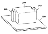
図13は第2従来例の分解斜視図、図14は第2従来例の外観斜視図である。このものは、キャビネット、具体的には薄型テレビジョン受像機の樹脂製のリアキャビネット100の内側に、図13のように樹脂でなる四角筒形の保持枠130を一体に成形しておき、その保持枠130に板金製の取付け部材200を圧入して嵌め込んだ後、保持枠130に樹脂製の箱形カバー体300を被せることにより、その箱形カバー体300で保持枠130の開口部131を覆う、という構成が採用されている。この第2従来例において、取付け部材200には、リアキャビネット100側の開口(図に現れていない)に対峙するねじ孔210が設けられている。また、リアキャビネット100には、箱形カバー体300を固定するための係合フック140が設けられている。
FIG. 13 is an exploded perspective view of the second conventional example, and FIG. 14 is an external perspective view of the second conventional example. In this, a rectangular
図12を参照して説明した第1従来例は、取付け部材200をリアキャビネット100にビス止めする作業が煩わしく、特に、リアキャビネット100の複数箇所(たとえば4箇所)に取付け部材200を装着する必要があるときには、それらの各箇所でのビス止め作業が必要になって組立作業性が極端に低下してしまうという問題があった。また、近時ではテレビジョン受像機の薄形化が促進されているために、テレビジョン受像機に必須の制御用の配線基板(不図示)に取付け部材200の取付け位置が近接する傾向がある。このことにより、配線基板に形成された制御回路と取付け部材200との相互間に要求される空間距離を十分に広く確保するためや、ESD試験対策(静電気破壊試験対策)のためなどに、配線基板に設けられる制御回路の存在しない禁止領域を広く確保する必要が生じ、そのことが基板設計にとって不利な状況を招いているという問題もあった。
In the first conventional example described with reference to FIG. 12, the work of screwing the
これに対し、図13及び図14を参照して説明した第2従来例では、樹脂製の保持枠130に挿入された取付け部材200が非導電体である樹脂で成形された箱形カバー体300によって覆われているので、取付け部材200からの静電気の放電が配線基板の制御回路に悪影響を及ぼす範囲が狭くなって、配線基板に設けられる制御回路の存在しない禁止領域を狭くすることが可能になり、それだけ基板設計にとって有利になるという利点がある。また、この第2従来例では、リアキャビネット100の4箇所に取付け部材200を装着するときでも、取付け部材200を保持枠130に挿入するだけでその取付け部材200を固定する構成を採用し得るので、ビス止め作業によって組立作業性が低下するという事態を回避することも可能である。
On the other hand, in the second conventional example described with reference to FIGS. 13 and 14, the box-
しかしながら、上記の第2従来例は、組立工程に関して、保持枠130に取付け部材200を圧入して強嵌合させる工程と、取付け部材200を挿入した保持枠130に箱形カバー体300を被せる工程との2工程が必要になる。そのため、取付け部材200を取り外すことが極めて困難になる。また、保持枠130をリアキャビネット100に成形しておく必要があるほか、箱形カバー体300を余分に成形する必要がある。
However, in the second conventional example, with respect to the assembling process, the step of press-fitting the
本発明は、以上に鑑みてなされたものであり、第2従来例に比べ、組立作業性が改善されて1工程で組立工程を終えることができる一方で、一旦組み立てた取付け部材を容易に取り外すことが可能であり、しかも、第2従来例のように箱形カバー体300を余分に成形する必要性を無くすることによって、組立工程の簡略化と部品点数の削減を図ることができるにもかかわらず、配線基板に設けられる制御回路の存在しない禁止領域を狭くすることが可能になる壁掛け金具取付け部材の装着部構造を提供することを目的としている。
The present invention has been made in view of the above, and as compared with the second conventional example, the assembly workability is improved and the assembly process can be completed in one process, while the assembly member once assembled is easily removed. In addition, it is possible to simplify the assembly process and reduce the number of components by eliminating the need to form the box-
本発明に係る壁掛け金具取付け部材の装着部構造は、壁掛け金具を相手方部材とする板金製の取付け部材が、樹脂製キャビネットの内側に配備される配線基板との対向位置で上記キャビネットに装着されていて、上記取付け部材に設けられたねじ孔が、上記キャビネットに開設された開口に対峙していると共に、その取付け部材が上記キャビネットに樹脂で一体成形された静電気遮蔽機能を備えるカバー体で覆われてなる。 In the mounting structure of the wall mounting bracket mounting member according to the present invention, the mounting member made of sheet metal having the wall mounting bracket as a counterpart member is mounted on the cabinet at a position facing the wiring board disposed inside the resin cabinet. In addition, the screw hole provided in the mounting member is opposed to the opening formed in the cabinet, and the mounting member is covered with a cover body having an electrostatic shielding function integrally formed with resin in the cabinet. It becomes.
そして、上記カバー体が、側壁部と天壁部とを有して、その側壁部の1箇所に上記取付け部材を出し入れ可能な開口部が形成されたフード形状の囲構体でなり、上記開口部を通して上記カバー体に挿入された上記取付け部材が上記開口部から抜け出ることを阻止する係合機構を備えていて、その係合機構が、カバー体の上記天壁部に設けられた凹入部と、上記取付け部材に設けられて上記凹入部に係合する側面視鋸歯形状の突起とでなる。 The cover body is a hood-shaped enclosure having a side wall portion and a top wall portion, and an opening portion into which the mounting member can be taken in and out is formed at one position of the side wall portion. An engagement mechanism for preventing the attachment member inserted through the cover body from coming out of the opening, and the engagement mechanism includes a recessed portion provided in the top wall portion of the cover body; The protrusion is provided on the attachment member and has a sawtooth shape in a side view and engages with the recessed portion.
また、上記突起が、上記取付け部材に具備された板片部に切起し形成され、かつ、上記凹入部に嵌合されてその凹入部の壁面に上記カバー体からの上記取付け部材の抜け出し方向で対峙している係合部と、上記取付け部材を上記カバー体に挿入する工程でカバー体の上記天壁部と摺動してその天壁部を弾性に抗して変形させながら上記係合部を上記凹入部に導入する誘導ガイド面と、を備えていると共に、上記係合部が、上記板片部の板面から切り立った上記突起の端面によって形成されている。 Further, the protrusion is formed by cutting and raising the plate piece provided in the mounting member, and is fitted into the recessed portion so that the mounting member is pulled out from the cover body on the wall surface of the recessed portion. The engaging portion facing each other and the engaging member while sliding the top wall portion of the cover body in a step of inserting the mounting member into the cover body and deforming the top wall portion against elasticity A guide guide surface for introducing the portion into the recessed portion, and the engaging portion is formed by an end surface of the protrusion standing up from the plate surface of the plate piece portion.
この構成を備えた壁掛け金具取付け部材の装着部構造によると、取付け部材に設けられたねじ孔を利用することによって、壁掛け金具を、それと一体の取付けボルト又は壁掛け金具とは別体の取付けボルトを用いて取付け部材にねじ止めすることが可能である。また、板金製の取付け部材が静電気遮蔽機能を備えるカバー体で覆われていることにより、取付け部材と配線基板との空間距離を短くすることが可能になり、当該装着部構造を備えるテレビジョン受像機などの画像表示装置の薄形化を促進しやすくなる。 According to the mounting structure of the wall mounting bracket mounting member having this configuration, the wall mounting bracket can be attached to the wall mounting bracket or a mounting bolt separate from the wall mounting bracket by using a screw hole provided in the mounting member. It can be used to screw onto the mounting member. Further, since the attachment member made of sheet metal is covered with a cover body having a static electricity shielding function, the spatial distance between the attachment member and the wiring board can be shortened, and a television receiver having the mounting portion structure is provided. It is easy to promote thinning of the image display device such as a machine.
そして、本発明では、係合機構の作用により、カバー体にその開口部から挿入した取付け部材のその開口部からの抜け出しが阻止されるため、キャビネットと共に樹脂で一体成形されているカバー体に取付け部材を挿入するという1工程を行うだけで当該装着部構造を組み立てることが可能になる。しかも、その係合機構が、カバー体側の凹入部と取付け部材側の側面視鋸歯形状の突起とによって構成されていることにより、カバー体をキャビネットに装着する手段として図12に示した第1従来例の取付けビス110を余分に用いる必要がない。また、図13及び図14に示した第2従来例の箱形カバー体300を余分に用いる必要もない。
In the present invention, since the attachment member inserted into the cover body from the opening is prevented from coming out of the opening by the action of the engagement mechanism, the attachment is attached to the cover body integrally molded with the resin together with the cabinet. The mounting portion structure can be assembled by performing only one step of inserting a member. In addition, since the engaging mechanism is constituted by a recessed portion on the cover body side and a sawtooth projection on the side of the mounting member, the first conventional technique shown in FIG. 12 as means for mounting the cover body on the cabinet. There is no need to use an
特に、本発明では、突起が取付け部材の板片部に切起し形成されていて、カバー体側の凹入部の壁面に対峙する係合部が上記板片部の板面から切り立った当該突起の端面によって形成されていることにより、取付け部材がカバー体からの抜け出し方向に強く引張られても、それによって突起と凹入部との係合状態が解除されて取付け部材がカバー体から抜け出てしまうという事態が起こり得ない。そのため、画像表示装置の運搬中や画像表示装置を床面に据え置いているようなときなどに、取付け部材がカバー体から不慮に抜け落ちてしまうという事態の起こる余地がない。これに対し、カバー体に挿入した取付け部材を取り出すときには、カバー体の天壁部を人力でその弾性に抗して撓ませながら突起と凹入部との係合状態を解除するという動作を通じて、カバー体から取付け部材を抜き出して取り外すことが可能である。その上、取付け部材をカバー体に挿入する工程では、突起の誘導ガイド面がカバー体の天壁部を弾性に抗して変形させながら突起の係合部を上記天壁部の凹入部に導入するという作用を発揮するため、取付け部材をカバー体に挿入するという、熟練を必要としない作業を行うだけで当該装着部構造が組み立てられる。 In particular, in the present invention, the projection is formed by cutting and raising the plate piece portion of the mounting member, and the engaging portion facing the wall surface of the recessed portion on the cover body side is cut from the plate surface of the plate piece portion. By being formed by the end face, even if the attachment member is strongly pulled in the direction of withdrawal from the cover body, the engagement state between the protrusion and the recessed portion is thereby released and the attachment member comes out of the cover body. Things can't happen. Therefore, there is no room for occurrence of a situation in which the attachment member is accidentally dropped from the cover body when the image display device is being transported or when the image display device is placed on the floor. On the other hand, when removing the mounting member inserted into the cover body, the cover body is moved through the operation of releasing the engagement state between the protrusion and the recessed portion while bending the top wall portion of the cover body against its elasticity by human power. The attachment member can be extracted from the body and removed. In addition, in the step of inserting the mounting member into the cover body, the guide guide surface of the projection introduces the engaging portion of the projection into the recessed portion of the top wall portion while deforming the top wall portion of the cover body against elasticity. In order to exhibit the effect of performing this, the mounting portion structure is assembled only by performing an operation that does not require skill, such as inserting the attachment member into the cover body.
本発明では、上記取付け部材が、上記ねじ孔を有するベース片部とこのベース片部に対向する上記板片部とこれらのベース片部及び板片部の後端部同士を連結している中間片部とを有する側面視コ字形に形成されているのに対し、上記カバー体が、上記凹入部を備え、かつ、上記キャビネットの内面に対して上記開口部に向かう上がり勾配を有する傾斜した上記天壁部を有することが望ましい。この構成であれば、取付け部材が側面視コ字形という簡素な形状に形成されているために、その取付け部材を容易に製作することができる。また、カバー体の天壁部が開口部に向かう上がり勾配を有するように傾斜しているので、開口部から取付け部材をカバー体の内部に挿入しやすいという利点がある。 In the present invention, the mounting member connects the base piece having the screw hole, the plate piece facing the base piece, and the base piece and the rear end of the plate piece. The cover body is provided with the recessed portion and has an inclined slope toward the opening with respect to the inner surface of the cabinet. It is desirable to have a top wall. With this configuration, since the attachment member is formed in a simple shape having a U-shape when viewed from the side, the attachment member can be easily manufactured. In addition, since the top wall portion of the cover body is inclined so as to have an upward slope toward the opening portion, there is an advantage that the attachment member can be easily inserted into the cover body from the opening portion.
本発明では、上記カバー体に、上記取付け部材のベース片部に当接してその浮き上がりを阻止する押えリブが一体に設けられていることが望ましい。この構成であれば、カバー体に組み付けられた取付け部材がその内部で浮き上がってがたつくという事態が起こらない。そのため、仮に画像表示装置を床面に据え置いて使用するような場合でも、スピーカの出力に伴うビビリ音が生じにくい。 In the present invention, it is desirable that the cover body is integrally provided with a presser rib that comes into contact with the base piece of the mounting member and prevents the cover member from being lifted. If it is this structure, the situation where the attachment member assembled | attached to the cover body floats inside and does not occur does not occur. For this reason, even when the image display apparatus is used while being placed on the floor surface, chatter noise accompanying the output of the speaker is less likely to occur.
本発明では、上記ベース片部に当接している上記押えリブの当り面が、上記キャビネットの内面に対して上記開口部に向かう上がり勾配を有する傾斜面として形成されていることが望ましい。この構成を採用すると、カバー体の開口部から取付け部材をカバー体の内部に挿入しやすくなる。 In the present invention, it is desirable that the contact surface of the presser rib in contact with the base piece portion is formed as an inclined surface having an upward gradient toward the opening with respect to the inner surface of the cabinet. If this structure is employ | adopted, it will become easy to insert an attachment member into the inside of a cover body from the opening part of a cover body.
本発明では、上記取付け部材を上記カバー体に挿入する工程で、上記誘導ガイド面が上記カバー体の天壁部と摺動してその天壁部を弾性に抗して変形させ得るように、取付け部材の上記突起と上記板片部の後端部との相互間隔を定めてあることが望ましい。この構成であれば、取付け部材の板片部を形成している板金の厚さをそれほど考慮することなく、その板片部の剛性を、弾性変形性を有することが要求されるカバー体の天壁部よりも大きくすることが容易に可能になる。 In the present invention, in the step of inserting the attachment member into the cover body, the guide guide surface can slide with the top wall portion of the cover body and deform the top wall portion against elasticity, It is desirable that the mutual interval between the projection of the mounting member and the rear end portion of the plate piece portion is determined. With this configuration, the thickness of the sheet metal forming the plate piece portion of the mounting member is not so much considered, and the rigidity of the plate piece portion is the top of the cover body that is required to have elastic deformability. It can be easily made larger than the wall portion.
ところで、本発明では、板金製の取付け部材が静電気遮蔽機能を備えるカバー体で覆われているために、配線基板と取付け部材との空間距離を短くしても、配線基板に設けられる制御回路の存在しない禁止領域を狭くすることが可能である。しかしながら、カバー体がその側壁部に開口部を有しているために、その開口部の形成箇所ではカバー体による静電気遮蔽機能が損なわれている。 By the way, in the present invention, since the mounting member made of sheet metal is covered with a cover body having an electrostatic shielding function, the control circuit provided on the wiring board can be provided even if the spatial distance between the wiring board and the mounting member is shortened. It is possible to narrow the prohibited area that does not exist. However, since the cover body has an opening in its side wall, the electrostatic shielding function by the cover is impaired at the location where the opening is formed.
この点を改善して配線基板の禁止領域を狭く抑えるためには、上記カバー体を形成している囲構体が、そのカバー体に挿入された取付け部材の後方位置まで延び出ている、という構成を採用することが有益である。この構成を採用すると、カバー体の開口部から放出される静電気の拡がり領域を狭く抑えることが可能になるので、それだけ配線基板の禁止領域を狭くすることが可能になる。同様に、上記凹入部を、カバー体の上記天壁部に開設された貫通孔部によって形成した場合には、その貫通孔部の孔縁部に当該カバー体の外側に延び出た筒部を連設しておくことが、配線基板の禁止領域を狭くするために有益である。 In order to improve this point and to keep the prohibited area of the wiring board narrow, the structure forming the cover body extends to the rear position of the mounting member inserted in the cover body. It is beneficial to adopt By adopting this configuration, it is possible to reduce the area where static electricity discharged from the opening of the cover body is narrowed, so that the prohibited area of the wiring board can be narrowed accordingly. Similarly, when the recessed portion is formed by a through-hole portion formed in the top wall portion of the cover body, a cylindrical portion that extends outside the cover body is formed at the hole edge of the through-hole portion. It is beneficial to keep the connection in order to narrow the prohibited area of the wiring board.
以上のように、本発明の壁掛け金具取付け部材の装着部構造によれば、組立作業性が改善されて、取付け部材をカバー体にその開口部から挿入だけの1工程で組立工程を終えることができる。しかも、取付け部材をビス止めしたりする必要がなく、また、取付け部材を覆う箱形カバー体を余分に使用する必要がないので、それだけ組立工程の簡略化と部品点数の削減を図ることができ、また、カバー体に取り付けた取付け部材を取り外すことも容易に可能になる。それにもかかわらず、キャビネットに設けたカバー体によって板金製の取付け部材が覆われていることにより、配線基板に設けられる制御回路の存在しない禁止領域を狭くすることも可能になる。 As described above, according to the mounting structure of the wall mounting bracket attachment member of the present invention, the assembly workability is improved, and the assembly process can be completed in one step only by inserting the attachment member into the cover body from the opening. it can. Moreover, there is no need to screw the mounting member, and there is no need to use an extra box cover that covers the mounting member, so that the assembly process can be simplified and the number of parts can be reduced. Also, it is possible to easily remove the attachment member attached to the cover body. Nevertheless, since the attachment member made of sheet metal is covered by the cover body provided in the cabinet, it is possible to narrow the prohibited area where the control circuit provided in the wiring board does not exist.
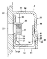
図1は薄型テレビジョン受像機の概略背面図、図2は図1のII−II線に沿う部分の概略縦断側面図、図3は図2のIII部を拡大した断面図である。 1 is a schematic rear view of a flat-screen television receiver, FIG. 2 is a schematic longitudinal side view of a portion along the line II-II in FIG. 1, and FIG. 3 is an enlarged sectional view of a portion III in FIG.
図1及び図2のように、図例の薄型テレビジョン受像機は、液晶パネル11や配線基板12などを備えた液晶モジュール10が、フロントキャビネット21とリアキャビネット22とによって形成されたキャビネット20に収容されている。そして、リアキャビネット22の中央部の4箇所に取付け部材30(図3参照)が設けられていて、その取付け部材30をリアキャビネット22に装着するための構造に、本発明に係る装着部構造Aが適用されている。
As shown in FIG. 1 and FIG. 2, the thin television receiver of the illustrated example has a
この装着部構造Aでは、図3のように、板金製の取付け部材30が樹脂製のリアキャビネット22に装着されていて、その取付け部材30に設けられているねじ孔31が、リアキャビネット22に開設されている円形の開口23に対峙している。また、取付け部材30は液晶モジュール10の配線基板12(図2参照)に対向して位置している。さらに、取付け部材30は、リアキャビネット22に一体に樹脂で成形されているカバー体50によってそのほゞ全体が覆われている。
In the mounting portion structure A, as shown in FIG. 3, a sheet
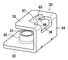
図4はカバー体50の構成を説明するための概略斜視図、図5は取付け部材30の構成を説明するための概略斜視図である。また、図6及び図7は組立手順を説明するための断面図である。
FIG. 4 is a schematic perspective view for explaining the configuration of the
図4のように、カバー体50はフード形状の囲構体でなる。すなわち、カバー体50を形成している囲構体のフード形状は、1箇所に開口部51が形成された側壁部52と天壁部56とによって形作られていて、側壁部52は、コ字形に連設された左右各側の壁部54,54及び奥側の壁部55(図3参照)を有している。そして、側壁部52は、リアキャビネット22の内面に略垂直に立ち上げられているのに対し、天壁部56は、リアキャビネット22の内面に対して、カバー体50の開口部51に向かって上がり勾配θ1(図6参照))を有するように傾斜している。したがって、リアキャビネット22と天壁部56との対向間隔は、奥側の壁部55に近い箇所から開口部51の形成箇所に近付くほど漸次広くなり、開口部51の形成箇所で最も広くなっている。また、天壁部50の幅方向中央部に貫通孔部でなる凹入部61が設けられている。
As shown in FIG. 4, the
図5のように、取付け部材30は、ベース片部32とこのベース片部32に間隔を隔てて対向する板片部33とこれらのベース片部32及び板片部33の後端部同士を連結している中間片部34とを有する側面視コ字形に形成されている。そして、ベース片部32にバーリング加工によって内向きに形成した短いボス状の筒部35の内周面にねじ溝を刻設することによって上記したねじ孔31が形成されている。また、板片部33の幅方向中央部に側面視鋸歯形状の突起65が切起し形成されている。この突起65の後側の端面は、板片部33の板面から略垂直に切り立っていて、その端面によってカバー体50側の天壁部56に設けられている凹入部61の壁面62に係合可能な係合部66が形成されている。また、突起65には、係合部66の頂部から板片部33の板面に向けて延びる前下りの傾斜面が形成されていて、この傾斜面が誘導ガイド面67とされている。この誘導ガイド面67は、取付け部材30をカバー体50に挿入する工程でカバー体50の天壁部56と摺動することにより、その天壁部56を弾性に抗して変形させながら突起65の係合部66をカバー体50の凹入部61に導入する作用を発揮する。
As shown in FIG. 5, the
上記したカバー体50側の凹入部61と取付け部材30側の突起65とは、開口部51を通してカバー体50に挿入された取付け部材30が開口部51から抜け出ることを阻止する係合機構60を構成している(図3及び図7参照)。
The recessed
次に、図6及び図7を参照して取付け部材30を組み付ける手順の一例を説明する。
Next, an example of a procedure for assembling the
この手順の最初の段階では、図6のように、取付け部材30のベース片部32をリアキャビネット22の内面側に向け、その板片部33をカバー体50の天壁部56側に向けた姿勢で、取付け部材30の前部をカバー体50の開口部51に挿入する。このときの挿入作業は、カバー体50の天壁部56が開口部51に向かって上がり勾配θ1を有するように傾斜していて、開口部51が広く確保されているために、熟練を要することなく容易に行うことができる。
In the first stage of this procedure, as shown in FIG. 6, the
次の段階では、図6の矢印Pのように取付け部材30の中間片部34を手の指などで押し付けることによって、取付け部材30をカバー体50の内部に押し込む。この押込み作業を行うと、取付け部材30のベース片部32がリアキャビネット22の内面を摺動し、それに伴って取付け部材30の突起65の誘導ガイド面67が、図6に示したようにカバー体50の天壁部56の端部に当接した後、カバー体50の天壁部56と摺動してその天壁部56を弾性に抗して矢印Yのようにリアキャビネット22から遠ざかる方向に弾性変形させながら突起65を天壁部56の凹入部61に導入する。そのため、天壁部56がその弾性により初期位置に復帰して、図7のように、突起65の係合部66も凹入部61に導入され、その係合部66が凹入部61の壁面62に接触状態又は非接触状態で対峙する。
In the next stage, the
以上説明したように、取付け部材30をカバー体50に挿入するという一工程を行うだけで、取付け部材30をリアキャビネット22に装着して組み立てを終えることができる。そのため、図12に示した第1従来例の取付けビス110を余分に用いたり、図13及び図14に示した箱形カバー体300を余分に用いたりする必要がなくなり、それだけ部品点数が削減され、組立工程も簡略化されている。
As described above, the assembly can be completed by attaching the
図7のように取付け部材30がリアキャビネット22に装着されている状態では、カバー体50の内部で取付け部材30ががたついたり、取付け部材30が開口部51から抜け出る方向に強く引張られたりしたとしても、突起65の係合面66が凹入部61の壁面62に係合するので、カバー体50から取付け部材30が抜け落ちるという事態が起こり得ない。言い換えると、凹入部61と突起65とによって形成されている係合機構60の作用によって、カバー体50からの取付け部材30の抜け出しが確実に阻止されている。
In the state where the
特に、この実施形態では、突起65の端面によって形成されている係合部66が板片部33の板面から略垂直に切り立っているために、取付け部材30が開口部51から抜け出る方向に強く引張られたとしても、その係合部66がカバー体50の天壁部56を押し上げて変形させながら凹入部61から抜け出るという事態が起こりにくくなっている。その結果、上記のように、係合機構60の作用によって、カバー体50からの取付け部材30の抜け出しが確実に阻止されている、ということが云える。ここに、係合部66を板片部33の板面から略垂直に切り立たせていることの利点がある。
In particular, in this embodiment, since the engaging
取付け部材30をカバー体50から取り出すときには、たとえば図7に仮想線で示したドライバやその他の棒状の工具Tなどを利用して人力でカバー体50の天壁部56を弾性に抗して矢印Uのように持ち上げることにより撓ませ、そうすることによって突起65の係合面66と凹入部61との係合状態を解除する。このようにすると、係合機構60の係合状態が解除されて、カバー体50から取付け部材30を抜き出して取り外すことが可能になる。この実施形態では、図5に示したように、取付け部材30の板片部33と中間片部34とによって形作られているコーナ部に開口36を形成してある。そして、上記工具Tを利用してカバー体50の天壁部56を矢印Uのように持ち上げて撓ませるときに、その工具Tを開口36に挿入することができるようになっている。そのため、天壁部56を工具Tで持ち上げるときに、工具Tを十分にカバー体50に十分な長さに亘って挿入することができるようになり、その結果、工具Tの先端が天壁部56から外れて天壁部56を損傷したりするおそれがなくなるという利点がある。
When the
図4のように、この実施形態では、カバー体50の左右の壁部54,54の各内面に、そのカバー体50の奥側の壁部55から開口部51に向かって延びる押えリブ57,57(図4の手前側の壁部54の押えリブ57は図に現れていない)を一体に設けてある。図7のように、この押えリブ57は、カバー体50に挿入されて係合機構60による抜止めがなされた取付け部材30のベース片部32を、リアキャビネット22との間に挟み込んでいる。そのため、取付け部材30がカバー体50の内部で浮き上がったりがたついたりすることが、押えリブ57の押付け作用によって防止される。図例では、ベース片部32に当接している押えリブ57の当り面58が、リアキャビネット22の内面に対して開口部51に向かう上がり勾配θ2を有する傾斜面として形成されている。そして、カバー体50の内部の奥側では、当り面58とリアキャビネット22の内面との対向間隔がベース片部32の肉厚寸法よりもやゝ狭くなり、カバー体50の開口部51側では、その対向間隔がベース片部32の肉厚寸法よりもやゝ広くなるように定めてある。そのため、カバー体50に取付け部材30を挿入すると、ベース片部32の前端部が当り面58とリアキャビネット22の内面とにより挟まれて、取付け部材30の浮き上がりやがたつきが防止されるという利点がある。また、取付け部材30をカバー体50に挿入する初期には、ベース片部32が当り面58とリアキャビネット22の内面との相互間に容易に挿入されるようになるという利点がある。
As shown in FIG. 4, in this embodiment, on the inner surfaces of the left and
以上説明した実施形態では、取付け部材30のほゞ全体を覆っているカバー体50の静電気遮蔽機能によって、取付け部材30から放出される静電気の量が削減されているけれども、カバー体50によって覆われていない部分、具体的には、カバー体50の開口部51に臨んでいる取付け部材30の中間片部34や、カバー体50の貫通孔部でなる凹入部61に嵌合している取付け部材30の突起65から放出される静電気は、カバー体50によって遮蔽されることなくその外側へ放出される。そのため、開口部51や凹入部61から放出される静電気をできるだけ少なくすることによって、配線基板12(図2参照)に設けられる制御回路の存在しない禁止領域の広さをできるだけ狭くすることができるようにするための対策を講じることが望まれる。そのために講じ得る有益な対策を図8〜図11を参照して次に説明する。
In the embodiment described above, although the amount of static electricity discharged from the mounting
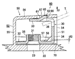
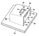
図8はカバー体50に挿入された取付け部材30が係合機構60によって抜け止めされている状態を示した斜視図、図9は同状態での当該装着部構造の作用を説明するための縦断側面図である。図10は変形例としてのカバー体に挿入された取付け部材が係合機構によって抜け止めされている状態を示した斜視図、図11は図10の状態での当該装着部構造の作用を説明するための縦断側面図である。
FIG. 8 is a perspective view showing a state in which the mounting
図8及び図9によって判るように、図例の装着部構造では、カバー体50を形成している囲構体が、カバー体50に挿入されている取付け部材30の後方位置まで延び出ている。図9には、取付け部材30の中間片部34からのカバー体50の出幅を符号L1で示してある。このようにカバー体50が取付け部材30の中間片部34の後方に突き出ていると、カバー体50の開口部51が取付け部材30の後端の中間片部34よりもさらに後方に位置するので、取付け部材30の中間片部34の周囲に向かう静電気の拡がり領域がカバー体50の左右の壁部54,54や天壁部56により制限されるようになる。したがって、図9のように取付け部材30の中間片部34から出幅L1だけ後方にカバー体50が突き出ていると、静電気の拡がり領域がその出幅L1に見合う範囲だけ狭めれる。図9には、カバー体50によって狭められた静電気の上下方向(取付け部材30の背高方向)での拡がり領域を符号W1で示してある。
As can be seen from FIGS. 8 and 9, in the illustrated mounting portion structure, the surrounding structure forming the
また、カバー体50の凹入部61は、天壁部56に開設された貫通孔部によって形成されているため、取付け部材30の突起65の形成箇所から放出される静電気の拡がり領域が、その凹入部61の開口幅に見合う範囲になる。図9には、凹入部61から放出される静電気の前後方向(取付け部材30の前後方向)での拡がり領域を符号Z1で示してある。
In addition, since the recessed
図10及び図11に示した装着部構造は、取付け部材30の中間片部34からのカバー体50を形成している囲構体の出幅を図9に示したL1よりも長くし、かつ、カバー体50の天壁部56の凹入部61を形成している貫通孔部の孔縁部に、カバー体50の外側に延び出た樹脂製の筒部59を一体に連設した事例である。図11には、取付け部材30の中間片部34からのカバー体50の出幅を符号L2で示してあり、この出幅L2は図9に示した出幅L1よりも長い。このように出幅L2を長くしておくと、取付け部材30の中間片部34の周囲に向かう静電気の拡がり領域がカバー体50の左右の壁部54,54や天壁部56により図9の場合よりも制限される。図11には、カバー体50によって狭められた静電気の上下方向(取付け部材30の背高方向)での拡がり領域を符号W2で示してある。このことから、図9や図11に示した出幅L1,L2が長いほど、カバー体50による静電気の拡がり領域がより広範囲に制限されて、配線基板12の禁止領域の広さを狭く抑える上で有益であるということができる。
The mounting portion structure shown in FIG. 10 and FIG. 11 is such that the protruding width of the enclosure forming the
また、図10及び図11に示した装着部構造のように、カバー体50の天壁部56の凹入部61を形成している貫通孔部の孔縁部に樹脂製の筒部59を連設しておくと、その筒部59が凹入部61から放出される静電気の拡がり領域を狭めることに役立つ。図11には筒部59によって狭められた静電気の前後方向での拡がり領域を符号Z2で示してあり、この拡がり領域Z2は、図9に示した拡がり領域Z1よりも狭くなっている。このことから、図11のようにカバー体50の天壁部56の凹入部61を形成している貫通孔部の孔縁部に樹脂製の筒部59を連設しておくことは、凹入部61から放出される静電気の拡がり領域Z2を狭くして配線基板12の禁止領域の広さを狭く抑える上で有益であるということができる。なお、筒部59を設けることに代えて、凹入部61を樹脂で閉塞してしまうことも考えられるけれども、そのようにすると、リアキャビネット22と共にカバー体50を樹脂で一体成形するという技術上の観点から、凹入部61の成形のために複雑な成形金型が必要になり、成形コストが高くつくことになる。
Further, as in the mounting portion structure shown in FIGS. 10 and 11, a
ところで、上記した実施形態の装着部構造の組立工程では、図6及び図7を参照して説明したように、取付け部材30をカバー体50に挿入する工程で、取付け部材30側の突起65の誘導ガイド面67がカバー体50の天壁部56と摺動してその天壁部56を弾性に抗して変形させる、という状況を生じさせるようになっている。この状況を作り出しておくと、本来的に、板金製の取付け部材30に備わっている板片部33が樹脂製のカバー体50に備わっている天壁部56よりも高剛性を有しているために、取付け部材30をカバー体50に小さな力で楽に挿入することが可能になる、という利点の得られることが判っている。そして、この状況は、カバー体50の天壁部56が取付け部材30の板片部33に比べて弾性変形しやすい性質を有している条件下で起こり得る。そこで、この条件を確実に満たすようにするために、この実施形態では、図11に示した取付け部材30の突起65を板片部33の後端部に近い箇所に切起し形成することによって、取付け部材30の突起65と板片部33の後端部との相互間隔(突起65と中間片部34との間隔)Xをできるだけ短くするという対策を講じている。こうしておくと、板金製の取付け部材が高剛性を有するということに加えて、板片部33を変形させるときの支点(板片部33の後端部)から作用点(突起の形成箇所)までの距離(上記相互間隔Xに相当する)が短くなるので、天壁部56を弾性に抗して変形させる、という状況を確実に作り出すことができる。
By the way, in the assembly process of the mounting portion structure of the above-described embodiment, as described with reference to FIGS. 6 and 7, in the process of inserting the
上記した実施形態では、図4などに示したように、リアキャビネット22の内面に複数条の背低リブ70を設けておくことによって、取付け部材30とカバー体50との寸法調整を行っている。また、この実施形態は、薄型テレビジョン受像機に適用されているけれども、他の種類の画像表示装置にも適用することが可能である。
In the above-described embodiment, as shown in FIG. 4 and the like, the dimensions of the mounting
12 配線基板
22 リアキャビネット(キャビネット)
23 開口
30 取付け部材
31 ねじ孔
32 ベース片部
33 板片部
34 中間片部
50 カバー体
51 開口部
52 側壁部
56 天壁部
57 押えリブ
58 押えリブの当り面
59 筒部
60 係合機構
61 凹入部
62 凹入部の壁面
65 突起
66 係合部
67 誘導ガイド面
X 突起と板片部の後端部との相互間隔
12
23
Claims (7)
上記カバー体が、側壁部と天壁部とを有して、その側壁部の1箇所に上記取付け部材を出し入れ可能な開口部が形成されたフード形状の囲構体でなり、
上記開口部を通して上記カバー体に挿入された上記取付け部材が上記開口部から抜け出ることを阻止する係合機構を備えていて、その係合機構が、カバー体の上記天壁部に設けられた凹入部と、上記取付け部材に設けられて上記凹入部に係合する側面視鋸歯形状の突起とでなり、
上記突起が、上記取付け部材に具備された板片部に切起し形成され、かつ、上記凹入部に嵌合されてその凹入部の壁面に上記カバー体からの上記取付け部材の抜け出し方向で対峙している係合部と、上記取付け部材を上記カバー体に挿入する工程でカバー体の上記天壁部と摺動してその天壁部を弾性に抗して変形させながら上記係合部を上記凹入部に導入する誘導ガイド面と、を備えていると共に、上記係合部が、上記板片部の板面から切り立った上記突起の端面によって形成されていることを特徴とする壁掛け金具取付け部材の装着部構造。 A mounting member made of a sheet metal having a wall mounting bracket as a counterpart member is attached to the cabinet at a position facing the wiring board disposed inside the resin cabinet, and the screw hole provided in the mounting member has the above-mentioned In the mounting structure of the wall mounting bracket mounting member that is opposed to the opening established in the cabinet, and whose mounting member is covered with a cover body having an electrostatic shielding function integrally formed with resin in the cabinet,
The cover body has a side wall portion and a top wall portion, and is a hood-shaped enclosure in which an opening portion in which the mounting member can be taken in and out is formed at one position of the side wall portion.
An engagement mechanism is provided for preventing the attachment member inserted into the cover body through the opening from coming out of the opening, and the engagement mechanism is a recess provided in the top wall of the cover body. And a projection in a sawtooth shape in a side view that is provided on the attachment member and engages with the recess.
The protrusion is formed by cutting and raising the plate piece provided in the mounting member, and is fitted into the recessed portion so as to face the wall surface of the recessed portion in the direction in which the mounting member is pulled out from the cover body. The engaging portion and the engaging member while sliding the top wall portion of the cover body in a step of inserting the mounting member into the cover body and deforming the top wall portion against elasticity. And a guide guide surface to be introduced into the recessed portion, and the engagement portion is formed by an end surface of the protrusion that stands up from the plate surface of the plate piece portion. Mounting part structure for members.
Priority Applications (2)
| Application Number | Priority Date | Filing Date | Title |
|---|---|---|---|
| JP2011054800A JP2012191081A (en) | 2011-03-11 | 2011-03-11 | Mounting part structure of wall-hanging fitting attachment member |
| US13/414,972 US8672425B2 (en) | 2011-03-11 | 2012-03-08 | Cabinet structure assembly |
Applications Claiming Priority (1)
| Application Number | Priority Date | Filing Date | Title |
|---|---|---|---|
| JP2011054800A JP2012191081A (en) | 2011-03-11 | 2011-03-11 | Mounting part structure of wall-hanging fitting attachment member |
Publications (1)
| Publication Number | Publication Date |
|---|---|
| JP2012191081A true JP2012191081A (en) | 2012-10-04 |
Family
ID=46794894
Family Applications (1)
| Application Number | Title | Priority Date | Filing Date |
|---|---|---|---|
| JP2011054800A Withdrawn JP2012191081A (en) | 2011-03-11 | 2011-03-11 | Mounting part structure of wall-hanging fitting attachment member |
Country Status (2)
| Country | Link |
|---|---|
| US (1) | US8672425B2 (en) |
| JP (1) | JP2012191081A (en) |
Cited By (1)
| Publication number | Priority date | Publication date | Assignee | Title |
|---|---|---|---|---|
| JP2017005347A (en) * | 2015-06-05 | 2017-01-05 | シャープ株式会社 | Display device and television receiver |
Families Citing this family (6)
| Publication number | Priority date | Publication date | Assignee | Title |
|---|---|---|---|---|
| JP2013130201A (en) * | 2010-04-08 | 2013-07-04 | Panasonic Corp | Structure for preventing incorrect insertion of screw |
| US10218933B2 (en) * | 2011-07-21 | 2019-02-26 | Funai Electric Co., Ltd. | Connecting structure, electrical device and television apparatus |
| JP5865722B2 (en) * | 2012-02-03 | 2016-02-17 | 三菱電機株式会社 | Video display device |
| CN103714750A (en) * | 2013-12-11 | 2014-04-09 | 上海三思电子工程有限公司 | Display screen allowing two-sided maintenance |
| CN105757413B (en) * | 2016-04-27 | 2018-05-29 | 合肥惠科金扬科技有限公司 | Display device support component and display device |
| TWI813989B (en) * | 2021-05-05 | 2023-09-01 | 精英電腦股份有限公司 | Movable locking ear and electrical device including the same |
Family Cites Families (16)
| Publication number | Priority date | Publication date | Assignee | Title |
|---|---|---|---|---|
| JP3095967B2 (en) * | 1994-08-31 | 2000-10-10 | 株式会社遠州 | Belt mounting bracket for seat belt device |
| JPH10215076A (en) | 1997-01-29 | 1998-08-11 | Matsushita Electric Ind Co Ltd | Wall mounting device for equipment casing |
| US7165371B2 (en) * | 2000-10-13 | 2007-01-23 | Altia Hashimoto Co., Ltd. | Automobile molding and fastener therefor |
| US20030019990A1 (en) * | 2001-07-26 | 2003-01-30 | Takehiro Co., Ltd. And Nagase & Co., Ltd. | Bracket for mounting speaker |
| US6715185B2 (en) * | 2002-07-25 | 2004-04-06 | Illinois Tool Works Inc. | Self aligning panel fastener |
| EP1394661A1 (en) * | 2002-08-28 | 2004-03-03 | Agilent Technologies, Inc. - a Delaware corporation - | Instrument enclosure apparatus |
| US6854941B2 (en) * | 2003-04-09 | 2005-02-15 | The Monadnock Company, Inc. | Clip nut |
| JP4079895B2 (en) | 2004-02-26 | 2008-04-23 | Necアクセステクニカ株式会社 | Wall mounting structure of equipment casing |
| US7178855B2 (en) * | 2005-03-03 | 2007-02-20 | Lear Corporation | Integral doghouse fastener with retaining feature |
| US20070107174A1 (en) * | 2005-11-17 | 2007-05-17 | Faurecia Interior Systems U.S.A., Inc. | Methods and apparatus for fastening panels |
| JP2008180318A (en) * | 2007-01-25 | 2008-08-07 | Okano Kiko Kk | Nut mounting structure |
| JP2008281024A (en) * | 2007-05-08 | 2008-11-20 | Funai Electric Co Ltd | Wall hanging appliance of thin display device |
| US8177466B2 (en) * | 2007-06-13 | 2012-05-15 | The Monadnock Company | Apparatus and methods for fastening a panel or other components |
| CN201096124Y (en) * | 2007-09-11 | 2008-08-06 | 延锋伟世通汽车饰件系统有限公司 | Clip holder |
| JP5371000B2 (en) | 2009-05-29 | 2013-12-18 | 愛知時計電機株式会社 | Electronic equipment mounting structure and equipment mounting adapter |
| JP2012191082A (en) * | 2011-03-11 | 2012-10-04 | Funai Electric Co Ltd | Mounting part structure of wall-hanging fitting attachment member |
-
2011
- 2011-03-11 JP JP2011054800A patent/JP2012191081A/en not_active Withdrawn
-
2012
- 2012-03-08 US US13/414,972 patent/US8672425B2/en active Active
Cited By (1)
| Publication number | Priority date | Publication date | Assignee | Title |
|---|---|---|---|---|
| JP2017005347A (en) * | 2015-06-05 | 2017-01-05 | シャープ株式会社 | Display device and television receiver |
Also Published As
| Publication number | Publication date |
|---|---|
| US20120229008A1 (en) | 2012-09-13 |
| US8672425B2 (en) | 2014-03-18 |
Similar Documents
| Publication | Publication Date | Title |
|---|---|---|
| JP2012191081A (en) | Mounting part structure of wall-hanging fitting attachment member | |
| CN109962355B (en) | Electronic device | |
| JP2012191082A (en) | Mounting part structure of wall-hanging fitting attachment member | |
| JP4341140B2 (en) | Electronics | |
| JP4241805B2 (en) | Power switch mounting structure for thin display devices | |
| US8971027B2 (en) | Display device cabinet | |
| JP5649638B2 (en) | Control device | |
| JPWO2015008551A1 (en) | Reinforcing leaf spring for plastic clips | |
| JP2005044919A (en) | Cabinet | |
| JP2011241973A (en) | Damper, light source device, and display device | |
| JP3076330U (en) | cabinet | |
| JP2018018452A (en) | Electronic apparatus and hard disk device holder | |
| JP2004221121A (en) | Hook mounting structure and frame structure using the same | |
| JP2011003713A (en) | Fixing structure for sheet metal member | |
| US20120302099A1 (en) | Electronic devices connector | |
| JP2005019805A (en) | Structure of cabinet | |
| EP4340557A1 (en) | Electronic device and assembly method for electronic device | |
| JP2013211294A (en) | Shield case assembly | |
| JP5718192B2 (en) | Connector and antenna device having the same | |
| JP5723516B2 (en) | LCD panel mounting structure | |
| JP2009302080A (en) | Apparatus cabinet | |
| JP5452786B2 (en) | Board assembly structure and electronic equipment | |
| JP6244782B2 (en) | Electronic equipment | |
| US20090218461A1 (en) | Base assembly capable of reducing the number of assembling steps | |
| JP4716914B2 (en) | Audio output device and display device including the same |
Legal Events
| Date | Code | Title | Description |
|---|---|---|---|
| A300 | Application deemed to be withdrawn because no request for examination was validly filed |
Free format text: JAPANESE INTERMEDIATE CODE: A300 Effective date: 20140513 |