EP1361096A2 - Device for detecting an obstacle in the opening area of a movable closure element of a vehicle - Google Patents
Device for detecting an obstacle in the opening area of a movable closure element of a vehicle Download PDFInfo
- Publication number
- EP1361096A2 EP1361096A2 EP03009067A EP03009067A EP1361096A2 EP 1361096 A2 EP1361096 A2 EP 1361096A2 EP 03009067 A EP03009067 A EP 03009067A EP 03009067 A EP03009067 A EP 03009067A EP 1361096 A2 EP1361096 A2 EP 1361096A2
- Authority
- EP
- European Patent Office
- Prior art keywords
- conductor
- sealing profile
- obstacle
- electrical conductor
- frame
- Prior art date
- Legal status (The legal status is an assumption and is not a legal conclusion. Google has not performed a legal analysis and makes no representation as to the accuracy of the status listed.)
- Granted
Links
Images


Classifications
-
- B—PERFORMING OPERATIONS; TRANSPORTING
- B60—VEHICLES IN GENERAL
- B60J—WINDOWS, WINDSCREENS, NON-FIXED ROOFS, DOORS, OR SIMILAR DEVICES FOR VEHICLES; REMOVABLE EXTERNAL PROTECTIVE COVERINGS SPECIALLY ADAPTED FOR VEHICLES
- B60J10/00—Sealing arrangements
-
- B—PERFORMING OPERATIONS; TRANSPORTING
- B60—VEHICLES IN GENERAL
- B60J—WINDOWS, WINDSCREENS, NON-FIXED ROOFS, DOORS, OR SIMILAR DEVICES FOR VEHICLES; REMOVABLE EXTERNAL PROTECTIVE COVERINGS SPECIALLY ADAPTED FOR VEHICLES
- B60J10/00—Sealing arrangements
- B60J10/30—Sealing arrangements characterised by the fastening means
-
- B—PERFORMING OPERATIONS; TRANSPORTING
- B60—VEHICLES IN GENERAL
- B60R—VEHICLES, VEHICLE FITTINGS, OR VEHICLE PARTS, NOT OTHERWISE PROVIDED FOR
- B60R13/00—Elements for body-finishing, identifying, or decorating; Arrangements or adaptations for advertising purposes
- B60R13/02—Internal Trim mouldings ; Internal Ledges; Wall liners for passenger compartments; Roof liners
- B60R13/0212—Roof or head liners
-
- E—FIXED CONSTRUCTIONS
- E05—LOCKS; KEYS; WINDOW OR DOOR FITTINGS; SAFES
- E05F—DEVICES FOR MOVING WINGS INTO OPEN OR CLOSED POSITION; CHECKS FOR WINGS; WING FITTINGS NOT OTHERWISE PROVIDED FOR, CONCERNED WITH THE FUNCTIONING OF THE WING
- E05F15/00—Power-operated mechanisms for wings
- E05F15/40—Safety devices, e.g. detection of obstructions or end positions
- E05F15/42—Detection using safety edges
- E05F15/46—Detection using safety edges responsive to changes in electrical capacitance
-
- F—MECHANICAL ENGINEERING; LIGHTING; HEATING; WEAPONS; BLASTING
- F16—ENGINEERING ELEMENTS AND UNITS; GENERAL MEASURES FOR PRODUCING AND MAINTAINING EFFECTIVE FUNCTIONING OF MACHINES OR INSTALLATIONS; THERMAL INSULATION IN GENERAL
- F16P—SAFETY DEVICES IN GENERAL; SAFETY DEVICES FOR PRESSES
- F16P3/00—Safety devices acting in conjunction with the control or operation of a machine; Control arrangements requiring the simultaneous use of two or more parts of the body
- F16P3/12—Safety devices acting in conjunction with the control or operation of a machine; Control arrangements requiring the simultaneous use of two or more parts of the body with means, e.g. feelers, which in case of the presence of a body part of a person in or near the danger zone influence the control or operation of the machine
-
- B—PERFORMING OPERATIONS; TRANSPORTING
- B60—VEHICLES IN GENERAL
- B60R—VEHICLES, VEHICLE FITTINGS, OR VEHICLE PARTS, NOT OTHERWISE PROVIDED FOR
- B60R13/00—Elements for body-finishing, identifying, or decorating; Arrangements or adaptations for advertising purposes
- B60R13/02—Internal Trim mouldings ; Internal Ledges; Wall liners for passenger compartments; Roof liners
- B60R2013/0287—Internal Trim mouldings ; Internal Ledges; Wall liners for passenger compartments; Roof liners integrating other functions or accessories
-
- E—FIXED CONSTRUCTIONS
- E05—LOCKS; KEYS; WINDOW OR DOOR FITTINGS; SAFES
- E05Y—INDEXING SCHEME RELATING TO HINGES OR OTHER SUSPENSION DEVICES FOR DOORS, WINDOWS OR WINGS AND DEVICES FOR MOVING WINGS INTO OPEN OR CLOSED POSITION, CHECKS FOR WINGS AND WING FITTINGS NOT OTHERWISE PROVIDED FOR, CONCERNED WITH THE FUNCTIONING OF THE WING
- E05Y2900/00—Application of doors, windows, wings or fittings thereof
- E05Y2900/50—Application of doors, windows, wings or fittings thereof for vehicles
- E05Y2900/53—Application of doors, windows, wings or fittings thereof for vehicles characterised by the type of wing
- E05Y2900/55—Windows
Definitions
- the invention relates to a device for detecting an obstacle in the opening area of one between an open position and a Closed position movable closing element of a motor vehicle, in particular an electrically powered window or a Sunroof.
- the device is sealing with a closing element Sealing profile provided, made of an elastic material manufactured and attached to a frame of the motor vehicle.
- the device is an obstacle in the opening area provided the closing element detecting sensor, the at least one an electric field in the opening region of the component generating having electrical conductor.
- Such a device is an anti-trap, the purpose serves to pinch about a human body part between the closing element and a closing element at least partially prevent surrounding edge.
- the known Devices have a sensor that detects the presence of an obstacle detected in the opening area of the closing element and a control signal provides for a driving the closing element drive.
- Dependence on the functioning of the sensor can be the well-known Devices divide into a pinch protection, the one requires physical contact of the obstacle, and anti-trap protection, which works without contact.
- An anti-trap to be counted to the first group becomes, for example described in DE 199 13 105 A1.
- the known device has a sealing profile, which seals a closing element and with two spaced from each other, electrically conductive areas is provided.
- a non-contact anti-trap protection is known from EP 1 154 110 A2 known.
- the operation of this device is based on a an obstacle caused in the opening area of a closing element Capacitive change of a generated between two electrical conductors electric field.
- One of the conductors, the sensor electrode is in a seal member sealing the sealing element integrated, whereas the other conductor, the ground electrode, for example by a Frame of a motor vehicle is formed, on which the sealing profile is attached.
- non-conductive materials such as wood or plastic, which has no or only a small capacitive change of cause electrical field to be able to recognize, that is the sensor electrode receiving area of the sealing profile deformable.
- the known devices are all associated with the disadvantage, in that an electrical conductor required for detecting an obstacle connected to a sealing member sealing the sealing profile is.
- the conductor is, for example, as a conductive region of the sealing profile designed or a wire by coextrusion in the
- Sealing profile is integrated. This has the consequence that the production costs the sealing profile are comparatively high. In addition, has the integration of the electrical conductor in the sealing profile as disadvantageous during assembly. Especially in curved areas, as in the transition from the A-pillar to the roof of a Motor vehicle, the sealing profile is compressed, so that the risk of Damage to the electrical conductor exists.
- the integration of the electrical conductor in the sealing profile requires a comparatively high logistical effort regarding the remaining components of the sensor, which are usually together with the Sealing profile be assembled. Last but not least, integration makes it difficult of the electrical conductor in the sealing profile troubleshooting a failure of the anti-trap.
- the invention has the object of developing a device of the type mentioned in that can be achieved compared to the prior art lower manufacturing costs and easier installation and maintenance.
- the conductor is arranged on a frame and / or the sealing profile at least partially concealing panel, which is fixedly mounted on the motor vehicle.
- the device according to the invention is based on the knowledge, the sealing profile and detecting an obstacle in the opening area the closing element required electrical conductor as a separate To form components.
- Such a design allows for a lower manufacturing costs of the sealing profile and contributes to the other to a practice-oriented installation and maintenance.
- Reason for this is in First of all the functional decoupling of sealing profile and electrical Ladder.
- the conductor is at one Paneling arranged, which the frame and / or the sealing profile at least partially obscured.
- the device of the invention makes take advantage of the fact that such a panel, for example in Shape of a trim strip, in most conventional closure elements, such as a windowpane, for aesthetic reasons anyway available is. An additional manufacturing and assembly costs fall in this respect not on.
- the device according to the invention reduces the logistic Effort, since all the components concerned with the sensor as purchased parts can be manufactured and delivered separately.
- the attachment of the electrical Ladder at one for detecting an obstacle in the opening area a closing element favorable location, without the arrangement of the To influence sealing profile. This allows for the special requirements certain closing elements, such as side doors, tailgate or trunk lid of a motor vehicle by a relatively large distance between sealing profile and potential Pinch zone are marked, take into account.
- the panel to the electric Insulation of the conductor of a dielectric material, preferably Plastic, to manufacture.
- a dielectric material in The preceding sense is understood to mean an insulating material which the propagation of the electric field without significant increase in the Capacity guaranteed.
- the head alternatively or additionally in a sheath made of an elastic, dielectric material to embed, which is attached to the panel.
- the the electric Conductor can protect against environmental influences protective sheathing made of an insulating rubber, such as sponge rubber, so that the conductor by coextrusion on economically favorable Embedding manner in the jacket.
- Such a development also allows the cladding made of metal, such as aluminum, to manufacture.
- the conductor is designed as a strand or flat band, to ensure a practice-oriented production.
- the conductor cohesively and / or positively and / or non-positively fastened to the panel.
- a positive connection or a frictional connection add-on cohesive connection, for example by Gluing, allows a reliable and permanent attachment of the Conductor.
- a positive and if necessary, non-positive attachment of the Ladder on the panel can be in an advantageous embodiment of the invention Realize device in that the conductor between set at least two formed on the panel webs is.
- the conductor can alternatively also by a projection formed on the panel be trapped.
- the conductor can also be in a gap formed on the panel be set.
- the cladding is elastically deformable at least in the region of the gap. Because in this way, the gap for easy insertion of the conductor be bent up. This also allows the gap in the form of an undercut to design, so that the inserted into the gap conductor is held positively and optionally also non-positively.
- the cladding is positively connected to the sealing profile, to a reliable attachment of the panel to the motor vehicle to reach.
- the cladding as going along the sealing profile To design an extending decorative molding to make one in a more aesthetic To convey an appealing visual impression.
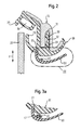
- a motor vehicle 10 is shown, in the region of a front door 11 with a driven by an electric motor 21 window 20 is provided.
- the window element representing a closing element 20 is in the drive direction y of the electric motor 21 between an open position and its closed position movable.
- the front door 11 has a frame 12 on, on which a sealing the window pane 20 sealing profile 30th is attached.
- the made of an electrically non-conductive elastomeric material fabricated sealing profile 30 is provided with a mounting portion 32nd provided, which extends in a channel 13 of the frame 12 and the Setting the sealing profile 30 holding lips 33 has.
- the sealing profile 30 is also provided with a hollow chamber 34 and sealing lips 35, which guide and seal the window pane 20.
- the sealing profile 30 has a recess 31 into which a decorative strip 50 positively engages.
- the trim strip 50 serves to the sealing profile 30 and the frame 12 at least partially to hide a for the viewer aesthetically pleasing optical To give an impression.
- Decorative strip 50 is provided with an electrical conductor 40.
- the electrical conductor 40 represents a sensor electrode, as described in EP 1 154 110 A2, and serves to generate an electric field.
- the grounded frame 12 thereby represents the electric field maintaining counter electrode.
- the trim strip 50 designed compliant so that upon physical contact with an obstacle, deformation the trim strip 50 occurs, the one evaluable as a control signal capacitive change of the electric field causes.
- the trim strip 50 is at least in Area of the electrical conductor 40 from the sealing profile 30 spaced. In this way, the trim strip 50 forms in the region of the conductor 40 a so-called soft spot.
- the electrical conductor as Litze 40 configured surrounded by a protective sheath 41 is.
- the sheath 41 is made of an elastomeric, non-conductive Material, such as sponge rubber, and is by means of coextrusion manufactured.
- the casing 41 is adhesively bonded to the decorative strip 50 attached.
- the electrical conductor is 40 also designed as a thin wire or stranded wire.
- the electrical conductor 40 is not integrated, for example by injection molding in the trim strip 50, but between two formed on the panel 50 webs 51 set.
- the webs 51 may be a continuous channel or from each other train separated posts. The provision of the webs 51 allows a logistically favorable separate provision of trim 50 and electrical conductor 40, with a simple and fast assembly is ensured.
- the embodiment shown in Fig. 3c has a flat band trained electrical conductor 40, which by a on the trim strip 50 trained projection 52 is clamped. Also in this case can the electrical conductor 40 and the trim strip 50 are provided separately and be connected in a simple and fast way.
- the trim strip 50 in the embodiment shown in Fig. 3d has a Gap 53, in which the electrical conductor 40 is fixed.
- the gap 53 is designed in the form of an undercut, which is a breaking out of the electrical conductor 40 positively prevented.
- the trim strip 50 in deform the bending direction w drawn in FIG. 3d, whereby the Gap 53 is bent.
- the electrical conductor 40 frictionally clamp in the gap 53.
- the arrangement of the electrical conductor 40 on the trim strip 50 also has the advantage that the sealing profile 30 in terms of shape and material independently of the electrical conductor 40 can be designed. moreover subject to the electrical conductor 40 due to the stationary arrangement the decorative strip 50 no or at most low dynamic loads, resulting in a low-wear and thus durable anti-trap protection is ensured.
- the flexibility of the trim can be 50 by a suitable choice of material and dimensioning to coordinate the respective application. Thus one can if necessary required soft spot in the sense mentioned above become.
- the electrical conductor 40 is in one Recess 61 of one consisting of an elastic material Covering 60 arranged.
- the cover 60 may, for example, by Coextrusion be made with the sealing profile 30 and in difference to an electrically conductive portion 36 of the sealing profile 30th Made of a non-conductive rubber.
- the recess 61 is with a gap 62 which extends through the sealing profile 30 therethrough extends and on the frame 12 facing side of the sealing profile 30 opens.
- the conductor can be 40 in the recess 61 in a simple manner by the Sealing profile 30 in unassembled state in the bending direction w stretched and the gap 62 is expanded in this way.
- the gap 62 is closed and the electrical Ladder 40 thus positively held in the recess 61, such as from Fig. 4a can be seen.
- a similar attachment of the electrical conductor 40 shows the embodiment according to FIGS. 5a to 5c.
- a cross-sectionally U-shaped fairing 70 has legs 71, 72 and a base 73.
- a recess 74 is provided, in which the electrical conductor 40 is arranged is.
- the electrical conductor 40 can be with unfolded leg 72 effortlessly insert into the recess 74.
- both the embodiment according to FIGS. 4a and 4b as well as the embodiment according to FIGS. 5a to 5c is characterized by a simple and reliable arrangement of the electrical conductor 40 in the panel 60, 70 off.
- the electrical conductor is side by side of the frame 12 forth in the recess 61, 74 introduced. This offers the advantage that on the one hand in the installed state of the panel 60, 70, the electrical conductor 40 inextricably disposed in the recess 61, 74 is. On the other hand, in this way, the one facing the viewer outer side of the panel 60, 70 in optical terms not through the recesses 61, 74 impaired.
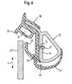
- FIG. 6 another embodiment is shown.
- the sealing profile 30 in this case attached to the frame 12 by means of a fastening clip 37.
- the one with the sealing profile 30 connected mounting clip 37 protrudes to this Purpose a bore 14 of the frame 12 to a sealing profile 30 facing away from surface 15 of the frame 12 to engage behind.
- the electrical conductor 40 is on a frame 12 laminating cladding 54 arranged.
- the electrical conductor 40 can with the panel 54 as in Figs. 2 and 3 a to d be shown connected.
- the above-described device for detecting an obstacle can not only be used as anti-pinch protection for the window pane 20 application but also for other closing elements of the motor vehicle 10, For example, a sunroof, a tailgate or a trunk lid, be used. Decisive is that a trim strip 50 or another type of trim on which the electrical conductor 40 can be fixed, can be provided.
Abstract
Description
Die Erfindung betrifft eine Vorrichtung zum Erkennen eines Hindernisses in dem Öffnungsbereich eines zwischen einer Offenstellung und einer Schließstellung bewegbaren Schließelements eines Kraftfahrzeugs, insbesondere einer elektrisch angetriebenen Fensterscheibe oder eines Schiebedachs. Die Vorrichtung ist mit einem das Schließelement abdichtenden Dichtungsprofil versehen, das aus einem elastischen Werkstoff gefertigt und an einem Rahmen des Kraftfahrzeugs befestigt ist. Darüber hinaus ist die Vorrichtung mit einem ein Hindernis in dem Öffnungsbereich des Schließelements erfassenden Sensor versehen, der wenigstens einen ein elektrisches Feld in dem Öffnungsbereich des Bauteils erzeugenden elektrischen Leiter aufweist.The invention relates to a device for detecting an obstacle in the opening area of one between an open position and a Closed position movable closing element of a motor vehicle, in particular an electrically powered window or a Sunroof. The device is sealing with a closing element Sealing profile provided, made of an elastic material manufactured and attached to a frame of the motor vehicle. About that In addition, the device is an obstacle in the opening area provided the closing element detecting sensor, the at least one an electric field in the opening region of the component generating having electrical conductor.
Eine derartige Vorrichtung stellt einen Einklemmschutz dar, der dazu dient, das Einklemmen etwa eines menschlichen Körperteils zwischen dem Schließelement und einer das Schließelement zumindest teilweise umgebenden Kante zu verhindern. Zu diesem Zweck weisen die bekannten Vorrichtungen einen Sensor auf, der die Anwesenheit eines Hindernisses in dem Öffnungsbereich des Schließelements erfaßt und ein Steuersignal für einen das Schließelement bewegenden Antrieb bereitstellt. In Abhängigkeit von der Funktionsweise des Sensors lassen sich die bekannten Vorrichtungen unterteilen in einen Einklemmschutz, der einen physischen Kontakt des Hindernisses erfordert, und einen Einklemmschutz, der berührungslos arbeitet.Such a device is an anti-trap, the purpose serves to pinch about a human body part between the closing element and a closing element at least partially prevent surrounding edge. For this purpose, the known Devices have a sensor that detects the presence of an obstacle detected in the opening area of the closing element and a control signal provides for a driving the closing element drive. In Dependence on the functioning of the sensor can be the well-known Devices divide into a pinch protection, the one requires physical contact of the obstacle, and anti-trap protection, which works without contact.
Ein zu der ersten Gruppe zu zählender Einklemmschutz wird beispielsweise in der DE 199 13 105 A1 beschrieben. Die bekannte Vorrichtung weist ein Dichtungsprofil auf, das ein Schließelement abdichtet und mit zwei voneinander beabstandeten, elektrisch leitfähigen Bereichen versehen ist.An anti-trap to be counted to the first group becomes, for example described in DE 199 13 105 A1. The known device has a sealing profile, which seals a closing element and with two spaced from each other, electrically conductive areas is provided.
Bei einem physischen Kontakt mit einem in dem Öffnungsbereich des Schließelements befindlichen Hindernis werden die leitfähigen Bereiche aneinander gedrückt, wodurch sich ein Schaltkontakt ergibt, der ein elektrisches Steuersignal auslöst.In physical contact with one in the opening area of the Closing element located obstacle become the conductive areas pressed together, resulting in a switching contact, which is an electrical Control signal triggers.
Ein berührungslos arbeitender Einklemmschutz ist aus der EP 1 154 110 A2 bekannt. Die Wirkungsweise dieser Vorrichtung beruht auf einer durch ein Hindernis in dem öffnungsbereich eines Schließelements hervorgerufenen kapazitiven Änderung eines zwischen zwei elektrischen Leitern erzeugten elektrischen Felds. Einer der Leiter, die Sensorelektrode, ist in einem das Schließelement abdichtenden Dichtungsprofil integriert, wohingegen der andere Leiter, die Grundelektrode, beispielsweise durch einen Rahmen eines Kraftfahrzeugs gebildet wird, an dem das Dichtungsprofil befestigt ist. Um auch nicht leitende Werkstoffe, wie beispielsweise Holz oder Kunststoff, die keine oder nur eine geringe kapazitive Änderung des elektrischen Felds hervorrufen, erkennen zu können, ist der die Sensorelektrode aufnehmende Bereich des Dichtungsprofils verformbar. Auf diese Weise ist sichergestellt, daß zumindest durch einen physischen Kontakt eines Hindernisses mit dem Dichtungsprofil eine Veränderung der Lage der Sensorelektrode eintritt, die eine kapazitive Änderung bewirkt.A non-contact anti-trap protection is known from EP 1 154 110 A2 known. The operation of this device is based on a an obstacle caused in the opening area of a closing element Capacitive change of a generated between two electrical conductors electric field. One of the conductors, the sensor electrode, is in a seal member sealing the sealing element integrated, whereas the other conductor, the ground electrode, for example by a Frame of a motor vehicle is formed, on which the sealing profile is attached. To non-conductive materials, such as wood or plastic, which has no or only a small capacitive change of cause electrical field to be able to recognize, that is the sensor electrode receiving area of the sealing profile deformable. To this Way, it is ensured that at least by a physical contact an obstacle with the sealing profile a change of Position of the sensor electrode enters, which causes a capacitive change.
Die bekannten Vorrichtungen sind allesamt mit dem Nachteil verbunden, daß ein zum Erfassen eines Hindernisses erforderlicher elektrischer Leiter mit einem das Schließelement abdichtenden Dichtungsprofil verbunden ist. Der Leiter ist dabei beispielsweise als leitfähiger Bereich des Dichtungsprofils ausgestaltet oder ein Draht, der durch Koextrusion in dasThe known devices are all associated with the disadvantage, in that an electrical conductor required for detecting an obstacle connected to a sealing member sealing the sealing profile is. The conductor is, for example, as a conductive region of the sealing profile designed or a wire by coextrusion in the
Dichtungsprofil integriert wird. Dies hat zur Folge, daß die Fertigungskosten des Dichtungsprofils vergleichsweise hoch sind. Darüber hinaus hat sich die Integration des elektrischen Leiters in das Dichtungsprofil als nachteilig bei der Montage herausgestellt. Vor allem in gekrümmten Bereichen, wie etwa beim Übergang von der A-Säule zu dem Dach eines Kraftfahrzeugs, wird das Dichtungsprofil gestaucht, so daß die Gefahr einer Beschädigung des elektrischen Leiters besteht.Sealing profile is integrated. This has the consequence that the production costs the sealing profile are comparatively high. In addition, has the integration of the electrical conductor in the sealing profile as disadvantageous during assembly. Especially in curved areas, as in the transition from the A-pillar to the roof of a Motor vehicle, the sealing profile is compressed, so that the risk of Damage to the electrical conductor exists.
Außerdem erfordert die Integration des elektrischen Leiters in das Dichtungsprofil einen vergleichsweise hohen logistischen Aufwand hinsichtlich der übrigen Bauteile des Sensors, die in der Regel zusammen mit dem Dichtungsprofil konfektioniert werden. Nicht zuletzt erschwert die Integration des elektrischen Leiters in das Dichtungsprofil die Fehlersuche bei einem Ausfall des Einklemmschutzes.In addition, the integration of the electrical conductor in the sealing profile requires a comparatively high logistical effort regarding the remaining components of the sensor, which are usually together with the Sealing profile be assembled. Last but not least, integration makes it difficult of the electrical conductor in the sealing profile troubleshooting a failure of the anti-trap.
Der Erfindung liegt die Aufgabe zugrunde, eine Vorrichtung der eingangs genannten Art dahingehend weiterzubilden, daß sich im Vergleich zum Stand der Technik geringere Fertigungskosten sowie eine einfachere Montage und Wartung erzielen lassen.The invention has the object of developing a device of the type mentioned in that can be achieved compared to the prior art lower manufacturing costs and easier installation and maintenance.
Zur Lösung dieser Aufgabe ist bei einer Vorrichtung mit den oben genannten Merkmalen in Übereinstimmung mit Anspruch 1 vorgesehen, daß der Leiter an einer den Rahmen und/oder das Dichtungsprofil zumindest teilweise verdeckenden Verkleidung angeordnet ist, die stationär an dem Kraftfahrzeug befestigt ist.To solve this problem is provided in a device having the above features in accordance with claim 1, that the conductor is arranged on a frame and / or the sealing profile at least partially concealing panel, which is fixedly mounted on the motor vehicle.
Die erfindungsgemäße Vorrichtung beruht auf der Erkenntnis, das Dichtungsprofil und den zum Erfassen eines Hindernisses in dem Öffnungsbereich des Schließelements erforderlichen elektrischen Leiter als separate Bauteile auszubilden. Eine solche Ausgestaltung ermöglicht zum einen geringere Fertigungskosten des Dichtungsprofils und trägt zum anderen zu einer praxisgerechten Montage und Wartung bei. Grund hierfür ist in erster Linie die funktionelle Entkopplung von Dichtungsprofil und elektrischem Leiter. Im Unterschied zum Stand der Technik ist der Leiter an einer Verkleidung angeordnet, die den Rahmen und/oder das Dichtungsprofil zumindest teilweise verdeckt. Die erfindungsgemäße Vorrichtung macht sich dabei zunutze, daß eine derartige Verkleidung, beispielsweise in Form einer Zierleiste, bei den meisten herkömmlichen Schließelementen, wie etwa eine Fensterscheibe, aus ästhetischen Gründen ohnehin vorhanden ist. Ein zusätzlicher Fertigungs- und Montageaufwand fällt insofern nicht an.The device according to the invention is based on the knowledge, the sealing profile and detecting an obstacle in the opening area the closing element required electrical conductor as a separate To form components. Such a design allows for a lower manufacturing costs of the sealing profile and contributes to the other to a practice-oriented installation and maintenance. Reason for this is in First of all the functional decoupling of sealing profile and electrical Ladder. In contrast to the prior art, the conductor is at one Paneling arranged, which the frame and / or the sealing profile at least partially obscured. The device of the invention makes take advantage of the fact that such a panel, for example in Shape of a trim strip, in most conventional closure elements, such as a windowpane, for aesthetic reasons anyway available is. An additional manufacturing and assembly costs fall in this respect not on.
Weiterhin reduziert die erfindungsgemäße Vorrichtung den logistischen Aufwand, da sämtliche den Sensor betreffende Bauteile als Zukaufsteile separat gefertigt und geliefert werden können. Schließlich gewährleistet die erfindungsgemäße Ausgestaltung die Anbringung des elektrischen Leiters an einer für die Erfassung eines Hindernisses in dem Öffnungsbereich eines Schließelements günstigen Stelle, ohne die Anordnung des Dichtungsprofils zu beeinflussen. Damit lassen sich den besonderen Anforderungen bestimmter Schließelemente, wie etwa Seitentüren, Heckklappe oder Kofferraumdeckel eines Kraftfahrzeugs, die durch einen verhältnismäßig großen Abstand zwischen Dichtungsprofil und potentieller Einklemmzone gekennzeichnet sind, Rechnung tragen.Furthermore, the device according to the invention reduces the logistic Effort, since all the components concerned with the sensor as purchased parts can be manufactured and delivered separately. Finally guaranteed the embodiment of the invention, the attachment of the electrical Ladder at one for detecting an obstacle in the opening area a closing element favorable location, without the arrangement of the To influence sealing profile. This allows for the special requirements certain closing elements, such as side doors, tailgate or trunk lid of a motor vehicle by a relatively large distance between sealing profile and potential Pinch zone are marked, take into account.
Vorteilhafte Ausgestaltungen der erfindungsgemäßen Vorrichtung stellen die Gegenstände der Ansprüche 2 bis 11 dar.Provide advantageous embodiments of the device according to the invention the objects of claims 2 to 11.
So ist es in Hinsicht auf eine wirksame Ausbildung eines elektrischen Felds durch den elektrischen Leiter von Vorteil, die Verkleidung zur elektrischen Isolierung des Leiters aus einem dielektrischen Werkstoff, vorzugsweise Kunststoff, zu fertigen. Unter einem dielektrischen Werkstoff im voranstehenden Sinne wird ein isolierendes Material verstanden, welches die Ausbreitung des elektrischen Felds ohne signifikante Erhöhung der Kapazität gewährleistet. So it is in terms of effective training of an electric Felds by the electrical conductor of advantage, the panel to the electric Insulation of the conductor of a dielectric material, preferably Plastic, to manufacture. Under a dielectric material in The preceding sense is understood to mean an insulating material which the propagation of the electric field without significant increase in the Capacity guaranteed.
Von besonderem Vorteil ist zudem, den Leiter alternativ oder zusätzlich in einer aus einem elastischen, dielektrischen Werkstoff gefertigten Ummantelung einzubetten, die an der Verkleidung befestigt ist. Die den elektrischen Leiter vor Umgebungseinflüssen schützende Ummantelung kann aus einem isolierenden Gummi, beispielsweise Moosgummi, bestehen, so daß sich der Leiter durch Koextrusion auf in wirtschaftlicher Hinsicht günstige Weise in der Ummantelung einbetten läßt. Eine solche Weiterbildung ermöglicht zudem, die Verkleidung aus Metall, beispielsweise Aluminium, zu fertigen.Of particular advantage is also, the head alternatively or additionally in a sheath made of an elastic, dielectric material to embed, which is attached to the panel. The the electric Conductor can protect against environmental influences protective sheathing made of an insulating rubber, such as sponge rubber, so that the conductor by coextrusion on economically favorable Embedding manner in the jacket. Such a development also allows the cladding made of metal, such as aluminum, to manufacture.
Vorteilhafterweise ist der Leiter als Litze oder flaches Band ausgestaltet, um eine praxisgerechte Fertigung zu gewährleisten. In Hinsicht auf eine einfache Montage ist es außerdem vorteilhaft, den Leiter stoffschlüssig und/oder formschlüssig und/oder kraftschlüssig an der Verkleidung zu befestigen. Vor allem eine zu etwa einem Formschluß oder einem Kraftschluß hinzutretende stoffschlüssige Verbindung, beispielsweise durch Kleben, ermöglicht eine zuverlässige und dauerhafte Befestigung des Leiters.Advantageously, the conductor is designed as a strand or flat band, to ensure a practice-oriented production. In terms of one simple installation, it is also advantageous, the conductor cohesively and / or positively and / or non-positively fastened to the panel. Especially one about about a positive connection or a frictional connection add-on cohesive connection, for example by Gluing, allows a reliable and permanent attachment of the Conductor.
Eine formschlüssige und bei Bedarf auch kraftschlüssige Befestigung des Leiters an der Verkleidung läßt sich in vorteilhafter Ausgestaltung der erfindungsgemäßen Vorrichtung dadurch realisieren, daß der Leiter zwischen wenigstens zwei an der Verkleidung ausgebildeten Stegen festgelegt ist. Zu Zwecken einer einfachen und schnellen Montage kann der Leiter alternativ auch durch einen an der Verkleidung ausgebildeten Vorsprung eingeklemmt werden.A positive and if necessary, non-positive attachment of the Ladder on the panel can be in an advantageous embodiment of the invention Realize device in that the conductor between set at least two formed on the panel webs is. For the purpose of easy and quick assembly, the conductor can alternatively also by a projection formed on the panel be trapped.
In einer bevorzugten Ausgestaltung der erfindungsgemäßen Vorrichtung kann der Leiter auch in einem an der Verkleidung ausgebildeten Spalt festgelegt sein. In diesem Fall hat es sich als zweckmäßig erwiesen, wenn die Verkleidung zumindest im Bereich des Spalts elastisch verformbar ist. Denn auf diese Weise kann der Spalt zum einfachen Einlegen des Leiters aufgebogen werden. Dies ermöglicht zudem, den Spalt in Form einer Hinterschneidung auszugestalten, so daß der in den Spalt eingelegte Leiter formschlüssig und gegebenenfalls auch kraftschlüssig gehalten wird.In a preferred embodiment of the device according to the invention the conductor can also be in a gap formed on the panel be set. In this case, it has proved to be useful if the cladding is elastically deformable at least in the region of the gap. Because in this way, the gap for easy insertion of the conductor be bent up. This also allows the gap in the form of an undercut to design, so that the inserted into the gap conductor is held positively and optionally also non-positively.
Bevorzugt ist die Verkleidung formschlüssig mit dem Dichtungsprofil verbunden, um eine zuverlässige Befestigung der Verkleidung an dem Kraftfahrzeug zu erreichen.Preferably, the cladding is positively connected to the sealing profile, to a reliable attachment of the panel to the motor vehicle to reach.
Schließlich wird in bevorzugter Weiterbildung der erfindungsgemäßen Vorrichtung vorgeschlagen, die Verkleidung als sich entlang des Dichtungsprofils erstreckende Zierleiste auszugestalten, um einen in ästhetischer Hinsicht ansprechenden optischen Eindruck zu vermitteln.Finally, in a preferred embodiment of the invention Device proposed, the cladding as going along the sealing profile To design an extending decorative molding to make one in a more aesthetic To convey an appealing visual impression.
Einzelheiten und weitere Vorteile der erfindungsgemäßen Vorrichtung ergeben sich aus der nachfolgenden Beschreibung bevorzugter Ausführungsbeispiele. In der die Ausführungsbeispiele lediglich schematisch darstellenden Zeichnungen veranschaulichen im einzelnen:
- Fig. 1
- eine Seitenansicht eines Kraftfahrzeugs;
- Fig. 2
- einen Schnitt entlang der Schnittlinie II in Fig. 1 bei einer ersten Ausführungsform der vorliegenden Erfindung;
- Fig. 3a
- eine Darstellung des in Fig. 2 mit III gekennzeichneten Bereich bei einer zweiten Ausführungsform der vorliegenden Erfindung;
- Fig. 3b
- eine Darstellung gemäß Fig. 3a bei einer dritten Ausführungsform der vorliegenden Erfindung;
- Fig. 3c
- eine Darstellung gemäß Fig. 3a bei einer vierten Ausführungsform der vorliegenden Erfindung;
- Fig. 3d
- eine Darstellung gemäß Fig. 3a bei einer fünften Ausführungsform der vorliegenden Erfindung;
- Fig. 4a
- einen Schnitt entlang der Schnittlinie II in Fig. 1 bei einer sechsten Ausführungsform der vorliegenden Erfindung;
- Fig. 4b
- eine Darstellung gemäß Fig. 4a, die ein gedehntes Dichtungsprofil zeigt;
- Fig. 5a
- einen Querschnitt durch eine Verkleidung im aufgeklappten Zustand;
- Fig. 5b
- einen Querschnitt durch die Verkleidung gemäß Fig. 5a im geschlossenen Zustand;
- Fig. 5c
- eine Darstellung gemäß Fig. 5b, welche die Befestigung der Verkleidung an einem Rahmen zeigt; und
- Fig. 6
- einen Schnitt entlang der Schnittlinie II in Fig. 1. bei einer siebten Ausführungsform der vorliegenden Erfindung.
- Fig. 1
- a side view of a motor vehicle;
- Fig. 2
- a section along the section line II in Figure 1 in a first embodiment of the present invention.
- Fig. 3a
- a representation of the marked in Fig. 2 with III area in a second embodiment of the present invention;
- Fig. 3b
- a representation of Figure 3a in a third embodiment of the present invention.
- Fig. 3c
- a representation of Figure 3a in a fourth embodiment of the present invention.
- Fig. 3d
- a representation of Figure 3a in a fifth embodiment of the present invention.
- Fig. 4a
- a section along the section line II in Figure 1 in a sixth embodiment of the present invention.
- Fig. 4b
- a view according to FIG. 4a, which shows a stretched sealing profile;
- Fig. 5a
- a cross section through a panel in the unfolded state;
- Fig. 5b
- a cross section through the panel of Figure 5a in the closed state.
- Fig. 5c
- a representation of Figure 5b, which shows the attachment of the panel to a frame. and
- Fig. 6
- a section along the section line II in Fig. 1 in a seventh embodiment of the present invention.
In Fig. 1 ist ein Kraftfahrzeug 10 dargestellt, das im Bereich einer Vordertür
11 mit einer durch einen Elektromotor 21 angetriebenen Fensterscheibe
20 versehen ist. Die ein Schließelement darstellende Fensterscheibe
20 ist in Antriebsrichtung y des Elektromotors 21 zwischen einer Offenstellung
und ihrer Schließstellung bewegbar.In Fig. 1, a
Wie Fig. 2 näher erkennen läßt, weist die Vordertür 11 einen Rahmen 12
auf, an dem ein die Fensterscheibe 20 abdichtendes Dichtungsprofil 30
befestigt ist. Das aus einem elektrisch nicht leitenden elastomeren Werkstoff
gefertigte Dichtungsprofil 30 ist mit einem Befestigungsabschnitt 32
versehen, der sich in einem Kanal 13 des Rahmens 12 erstreckt und zum
Festlegen des Dichtungsprofils 30 Haltelippen 33 aufweist. Das Dichtungsprofil
30 ist zudem mit einer Hohlkammer 34 und Dichtlippen 35 versehen,
welche die Fensterscheibe 20 führen und abdichten. Weiterhin
weist das Dichtungsprofil 30 eine Ausnehmung 31 auf, in die eine Zierleiste
50 formschlüssig eingreift. Die Zierleiste 50 dient dazu, das Dichtungsprofil
30 und den Rahmen 12 zumindest teilweise zu kaschieren, um einen
für den Betrachter in ästhetischer Hinsicht ansprechenden optischen
Eindruck zu erwecken. Die aus Kunststoff gefertigte und stationär angeordnete
Zierleiste 50 ist mit einem elektrischen Leiter 40 versehen. Der
elektrische Leiter 40 stellt eine Sensorelektrode dar, wie sie in der EP 1
154 110 A2 beschrieben ist, und dient dazu, ein elektrisches Feld zu erzeugen.
Der geerdete Rahmen 12 stellt dabei eine das elektrische Feld
aufrechterhaltende Gegenelektrode dar. Mittels einer nicht gezeigten
Auswerteeinheit ist es somit möglich, eine durch ein Hindernis in dem Öffnungsbereich
der Fensterscheibe 20 hervorgerufene kapazitive Änderung
des elektrischen Felds zu erfassen, um ein Steuersignal für den Elektromotor
21 bereitzustellen, das im Bedarfsfall den Elektromotor 21 stoppt.
Je nach Anwendungsfall kann die Zierleiste 50 nachgiebig ausgestaltet
sein, so daß bei einem physischen Kontakt mit einem Hindernis eine Verformung
der Zierleiste 50 auftritt, die eine als Steuersignal auswertbare
kapazitive Änderung des elektrischen Felds bewirkt. Um eine ausreichende
Verformungsfähigkeit sicherzustellen, ist die Zierleiste 50 zumindest im
Bereich des elektrischen Leiters 40 von dem Dichtungsprofil 30 beabstandet.
Auf diese Weise bildet die Zierleiste 50 im Bereich des Leiters 40 einen
sogenannten Softspot aus.As can be seen in more detail in FIG. 2, the front door 11 has a
In den Fign. 3a bis 3d sind alternative Ausführungsformen der Ausgestaltung
und der Anordnung des elektrischen Leiters 40 dargestellt. Gemeinsam
ist allen Ausführungsformen, daß der elektrische Leiter 40 auf der
dem Dichtungsprofil 30 zugewandten Seite der Zierleiste 50 angeordnet
und damit für einen Betrachter von außen nicht zu erkennen ist. Das optische
Erscheinungsbild der Zierleiste 50 wird durch den elektrischen Leiter
40 somit nicht beeinträchtigt.In the Fign. 3a to 3d are alternative embodiments of the embodiment
and the arrangement of the
Bei der in Fig. 3a gezeigten Ausführungsform ist der elektrische Leiter als
Litze 40 ausgestaltet, die von einer schützenden Ummantelung 41 umgeben
ist. Die Ummantelung 41 besteht aus einem elastomeren, nicht leitenden
Material, beispielsweise Moosgummi, und ist mittels Koextrusion
gefertigt. Die Ummantelung 41 ist durch Kleben stoffschlüssig an der Zierleiste
50 befestigt. In the embodiment shown in Fig. 3a, the electrical conductor as
Bei der in Fig. 3b gezeigten Ausführungsform ist der elektrische Leiter 40
gleichfalls als dünner Draht oder Litze ausgestaltet. Im Unterschied zu der
in Fig. 2 gezeigten Ausführungsform ist der elektrische Leiter 40 nicht
durch beispielsweise Spritzgießen in die Zierleiste 50 integriert, sondern
zwischen zwei an der Verkleidung 50 ausgebildeten Stegen 51 festgelegt.
Die Stege 51 können dabei einen kontinuierlichen Kanal oder voneinander
separierte Pfosten ausbilden. Das Vorsehen der Stege 51 ermöglicht eine
in logistischer Hinsicht günstige getrennte Bereitstellung von Zierleiste 50
und elektrischen Leiter 40, wobei eine einfache und schnelle Montage
sichergestellt ist.In the embodiment shown in FIG. 3b, the electrical conductor is 40
also designed as a thin wire or stranded wire. Unlike the
In Fig. 2 embodiment shown, the
Die in Fig. 3c gezeigte Ausführungsform weist einen als flaches Band
ausgebildeten elektrischen Leiter 40 auf, der durch einen an der Zierleiste
50 ausgebildeten Vorsprung 52 eingeklemmt ist. Auch in diesem Fall können
der elektrische Leiter 40 und die Zierleiste 50 getrennt bereitgestellt
und auf einfache und schnelle Weise miteinander verbunden werden.The embodiment shown in Fig. 3c has a flat band
trained
Die Zierleiste 50 bei der in Fig. 3d gezeigten Ausführungsform weist einen
Spalt 53 auf, in dem der elektrische Leiter 40 festgelegt ist. Der Spalt 53
ist in Form einer Hinterschneidung ausgestaltet, die ein Ausbrechen des
elektrischen Leiters 40 formschlüssig verhindert. Um den elektrischen Leiter
40 in den Spalt 53 einzuführen, ist es erforderlich, die Zierleiste 50 in
der in Fig. 3d eingezeichneten Biegerichtung w zu verformen, wodurch der
Spalt 53 aufgebogen wird. In Abhängigkeit von der Dimensionierung des
Spalts 53 ist es auf diese Weise zudem möglich, den elektrischen Leiter
40 kraftschlüssig in dem Spalt 53 einzuklemmen.The
Die zuvor beschriebenen Ausführungsformen einer Vorrichtung zum Erkennen
eines Hindernisses in dem Öffnungsbereich der Fensterscheibe
20 zeichnen sich im Vergleich zu einem konventionellen Einklemmschutz
durch vergleichsweise geringe Fertigungskosten sowie eine verhältnismäßig
einfache Montage und Wartung aus. Grund hierfür ist vornehmlich,
daß der elektrische Leiter 40 an der den Rahmen 12 und das Dichtungsprofil
30 zumindest teilweise kaschierenden Zierleiste 50 angeordnet ist.
Auf diese Weise ergibt sich sowohl für die Fertigung als auch für die Montage
respektive Wartung eine funktionelle Entkopplung von Dichtungsprofil
30 und das Erkennen eines Hindernisses in dem Öffnungsbereich der
Fensterscheibe 20 ermöglichenden elektrischen Leiter 40. Diese Entkopplung
reduziert nicht nur den Fertigungsaufwand sondern trägt auch dazu
bei, daß der elektrische Leiter 40 an einer für das Erkennen eines Hindernisses
günstigen Stelle angeordnet werden kann. Denn im Unterschied
zum Dichtungsprofil 30, das in der Regel neben einer zuverlässigen Abdichtung
auch eine Führung der Fensterscheibe 20 übernimmt, besteht für
die Anordnung der Zierleiste 50, die hauptsächlich ästhetischen Anforderungen
unterworfen ist, eine höhere Variabilität.The previously described embodiments of a device for recognizing
an obstacle in the opening area of the
Die Anordnung des elektrischen Leiters 40 an der Zierleiste 50 hat zudem
den Vorteil, daß das Dichtungsprofil 30 in bezug auf Form und Material
unabhängig von dem elektrischen Leiter 40 gestaltet werden kann. Überdies
unterliegt der elektrische Leiter 40 auf Grund der stationären Anordnung
der Zierleiste 50 keinen oder allenfalls geringen dynamischen Belastungen,
wodurch ein verschleißarmer und damit langlebiger Einklemmschutz
sichergestellt ist. Nicht zuletzt läßt sich die Nachgiebigkeit der Zierleiste
50 durch eine geeignete Werkstoffwahl und Dimensionierung auf
den jeweiligen Anwendungsfall abstimmen. Somit kann einem bei Bedarf
erforderlichen Softspot im oben genannten Sinne gezielt Rechnung getragen
werden.The arrangement of the
In den Fign. 4a und 4b ist eine weitere Ausführungsform der Anordnung
des elektrischen Leiters 40 dargestellt. Der elektrische Leiter 40 ist in einer
Ausnehmung 61 einer aus einem elastischen Werkstoff bestehenden
Verkleidung 60 angeordnet. Die Verkleidung 60 kann beispielsweise durch
Koextrusion mit dem Dichtungsprofil 30 gefertigt werden und im Unterschied
zu einem elektrisch leitenden Abschnitt 36 des Dichtungsprofils 30
aus einem nicht leitenden Gummi bestehen. Die Ausnehmung 61 ist mit
einem Spalt 62 verbunden, der sich durch das Dichtungsprofil 30 hindurch
erstreckt und auf der dem Rahmen 12 zugewandten Seite des Dichtungsprofils
30 mündet. Wie in Fig. 4b näher zu erkennen ist, läßt sich der Leiter
40 in die Ausnehmung 61 auf einfache Weise einführen, indem das
Dichtungsprofil 30 in nicht montiertem Zustand in Biegerichtung w gedehnt
und der Spalt 62 auf diese Weise ausgeweitet wird. In montiertem Zustand
des Dichtungsprofils 30 ist der Spalt 62 geschlossen und der elektrische
Leiter 40 damit formschlüssig in der Ausnehmung 61 gehalten, wie
aus Fig. 4a ersichtlich ist.In the Fign. 4a and 4b is another embodiment of the arrangement
of the
Eine ähnliche Befestigung des elektrischen Leiters 40 zeigt die Ausgestaltung
gemäß den Fign. 5a bis 5c. Eine im Querschnitt U-förmige Verkleidung
70 weist Schenkel 71, 72 und eine Basis 73 auf. In der Basis 73 der
beispielsweise aus Kunststoff gefertigten Verkleidung 70 ist eine Ausnehmung
74 vorgesehen, in welcher der elektrische Leiter 40 angeordnet
ist. Zwischen der Außenseite der Basis 73 und der Ausnehmung 74 befindet
sich ein verhältnismäßig dünner Steg 75, der in Art eines Filmscharniers
ein Schwenken des Schenkels 72 bezüglich des Schenkels 71 ermöglicht.
Wie in Fig. 5a zu erkennen ist, läßt sich der elektrische Leiter 40
bei aufgeklapptem Schenkel 72 mühelos in die Ausnehmung 74 einführen.
In geschlossenem Zustand wird der elektrische Leiter 40 formschlüssig
in der Ausnehmung 74 gehalten, wie in Fig. 5 gezeigt ist. Ein Aufklappen
der Schenkel 71, 72 wird in montiertem Zustand der Verkleidung 70
durch Klebemittel 76 verhindert, welche die Innenflächen der Schenkel 71,
72 mit gegenüberliegenden Flächen des Rahmens 12 verbinden, wie sich
Fig. 5c entnehmen läßt.A similar attachment of the
Sowohl die Ausgestaltung gemäß den Fign. 4a und 4b als auch die Ausgestaltung
gemäß den Fign. 5a bis 5c zeichnet sich durch eine einfache
und zuverlässige Anordnung des elektrischen Leiters 40 in der Verkleidung
60, 70 aus. In beiden Fällen wird der elektrische Leiter von Seiten
des Rahmens 12 her in die Ausnehmung 61, 74 eingeführt. Dies bietet
den Vorteil, daß zum einen in eingebautem Zustand der Verkleidung 60,
70 der elektrische Leiter 40 unlösbar in der Ausnehmung 61, 74 angeordnet
ist. Zum anderen wird auf diese Weise die dem Betrachter zugewandte
äußere Seite der Verkleidung 60, 70 in optischer Hinsicht nicht durch
die Ausnehmungen 61, 74 beeinträchtigt.Both the embodiment according to FIGS. 4a and 4b as well as the embodiment
according to FIGS. 5a to 5c is characterized by a simple
and reliable arrangement of the
In Fig. 6 ist eine weitere Ausführungsform dargestellt. Im Unterschied zu
der Ausgestaltung gemäß Fig. 2 ist das Dichtungsprofil 30 in diesem Fall
mittels eines Befestigungsclips 37 an dem Rahmen 12 befestigt. Der mit
dem Dichtungsprofil 30 verbundene Befestigungsclip 37 durchragt zu diesem
Zweck eine Bohrung 14 des Rahmens 12, um eine dem Dichtungsprofil
30 abgewandte Fläche 15 des Rahmens 12 zu hintergreifen. Der
elektrische Leiter 40 ist an einer den Rahmen 12 kaschierenden Verkleidung
54 angeordnet. Der elektrische Leiter 40 kann dabei mit der Verkleidung
54 wie in den Fign. 2 und 3 a bis d gezeigt verbunden sein.6, another embodiment is shown. In contrast to
the embodiment of FIG. 2 is the sealing
Die zuvor beschriebene Vorrichtung zum Erkennen eines Hindernisses
kann nicht nur als Einklemmschutz für die Fensterscheibe 20 Anwendung
finden, sondern auch für andere Schließelemente des Kraftfahrzeugs 10,
beispielsweise einem Schiebedach, einer Heckklappe oder eines Kofferraumdeckels,
eingesetzt werden. Maßgeblich dabei ist, daß eine Zierleiste
50 oder eine andere Art von Verkleidung, an dem der elektrische Leiter 40
befestigt werden kann, sich vorsehen läßt. The above-described device for detecting an obstacle
can not only be used as anti-pinch protection for the
- 1010
- Kraftfahrzeugmotor vehicle
- 1111
- VordertürIn front of the door
- 1212
- Rahmenframe
- 1313
- Kanalchannel
- 1414
- Bohrungdrilling
- 1515
- Flächearea
- 2020
- Fensterscheibewindowpane
- 2121
- Elektromotorelectric motor
- 3030
- Dichtungsprofilweatherstrip
- 3131
- Ausnehmungrecess
- 3232
- Befestigungsabschnittattachment section
- 3333
- Haltelipperetaining lip
- 3434
- Hohlkammerhollow chamber
- 3535
- Dichtlippesealing lip
- 3636
- leitender Abschnittsenior section
- 3737
- Befestigungsclipmounting clip
- 4040
- elektrischer Leiterelectrical conductor
- 4141
- Ummantelungjacket
- 5050
- Zierleistemolding
- 5151
- Stegweb
- 5252
- Vorsprunghead Start
- 5353
- Spaltgap
- 5454
- Verkleidungpaneling
- 6060
- elastische Verkleidungelastic paneling
- 6161
- Ausnehmungrecess
- 6262
- Spaltgap
- 7070
- Verkleidungpaneling
- 7171
- Schenkelleg
- 7272
- Schenkelleg
- 7373
- BasisBase
- 7474
- Ausnehmungrecess
- 7575
- Stegweb
- 7676
- Klebemitteladhesive
- ww
- Biegerichtungbending direction
- yy
- Antriebsrichtungdriving direction
Claims (11)
Applications Claiming Priority (2)
| Application Number | Priority Date | Filing Date | Title |
|---|---|---|---|
| DE10220187 | 2002-05-06 | ||
| DE10220187A DE10220187B4 (en) | 2002-05-06 | 2002-05-06 | Device for detecting an obstacle in the opening region of a movable closing element of a motor vehicle |
Publications (3)
| Publication Number | Publication Date |
|---|---|
| EP1361096A2 true EP1361096A2 (en) | 2003-11-12 |
| EP1361096A3 EP1361096A3 (en) | 2004-11-17 |
| EP1361096B1 EP1361096B1 (en) | 2008-04-09 |
Family
ID=29225071
Family Applications (1)
| Application Number | Title | Priority Date | Filing Date |
|---|---|---|---|
| EP03009067A Expired - Lifetime EP1361096B1 (en) | 2002-05-06 | 2003-04-17 | Device for detecting an obstacle in the opening area of a movable closure element of a vehicle |
Country Status (5)
| Country | Link |
|---|---|
| US (1) | US20030233790A1 (en) |
| EP (1) | EP1361096B1 (en) |
| AT (1) | ATE391624T1 (en) |
| DE (2) | DE10220187B4 (en) |
| ES (1) | ES2306824T3 (en) |
Cited By (2)
| Publication number | Priority date | Publication date | Assignee | Title |
|---|---|---|---|---|
| EP1561623A2 (en) * | 2004-02-03 | 2005-08-10 | Gummi-Welz GmbH & Co. KG | Anti-jam finger guard with electric switch contact |
| WO2007093914A1 (en) * | 2006-02-17 | 2007-08-23 | Gdx North America Inc. | Portable object sensing assembly |
Families Citing this family (12)
| Publication number | Priority date | Publication date | Assignee | Title |
|---|---|---|---|---|
| DE102004002415B4 (en) * | 2004-01-16 | 2008-07-10 | Metzeler Automotive Profile Systems Gmbh | Device for controlling and monitoring a movable closing element, in particular an electrically driven window pane of a motor vehicle |
| US7963583B2 (en) | 2005-01-31 | 2011-06-21 | Edscha Cabrio-Dachsysteme Gmbh | Top for a convertible vehicle |
| JP5025651B2 (en) * | 2005-08-18 | 2012-09-12 | クーパー−スタンダード・オートモーティブ・インコーポレーテッド | Weather strip incorporating anti-pinch sensor, weather strip assembly, and method of forming weather strip |
| GB2435517A (en) * | 2006-02-17 | 2007-08-29 | Gdx North America Inc | Vehicle opening sensor device |
| GB2435515A (en) * | 2006-02-17 | 2007-08-29 | Gdx North America Inc | Vehicle window sensor |
| DE202009009028U1 (en) | 2009-07-01 | 2010-12-30 | Brose Fahrzeugteile Gmbh & Co. Kommanditgesellschaft, Hallstadt | Capacitive sensor unit |
| US8493081B2 (en) | 2009-12-08 | 2013-07-23 | Magna Closures Inc. | Wide activation angle pinch sensor section and sensor hook-on attachment principle |
| US9234979B2 (en) | 2009-12-08 | 2016-01-12 | Magna Closures Inc. | Wide activation angle pinch sensor section |
| JP5126271B2 (en) * | 2010-03-31 | 2013-01-23 | 豊田合成株式会社 | Long sensor |
| US8615927B2 (en) * | 2011-11-23 | 2013-12-31 | GM Global Technology Operations LLC | Noncontact obstacle detection system using RFID technology |
| DE102017208791A1 (en) | 2017-05-24 | 2018-11-29 | Brose Fahrzeugteile Gmbh & Co. Kommanditgesellschaft, Bamberg | Capacitive proximity sensor |
| US20210148152A1 (en) * | 2019-11-15 | 2021-05-20 | Uusi, Llc | Sensor for anti-entrapment system |
Citations (5)
| Publication number | Priority date | Publication date | Assignee | Title |
|---|---|---|---|---|
| US3830018A (en) * | 1970-02-17 | 1974-08-20 | Toyota Motor Co Ltd | Safety device for power window |
| GB2282848A (en) * | 1993-10-18 | 1995-04-19 | Draftex Ind Ltd | Safety-control for vehicle window |
| EP0648628A1 (en) * | 1993-10-18 | 1995-04-19 | Draftex Industries Limited | Movable-window safety device |
| US5621290A (en) * | 1993-10-18 | 1997-04-15 | Draftex Industries Limited | Movable-window safety device |
| EP0829385A1 (en) * | 1996-09-17 | 1998-03-18 | Automobiles Peugeot | Sealing arrangement between two elements and vehicle roof provided with such sealing arrangement |
Family Cites Families (14)
| Publication number | Priority date | Publication date | Assignee | Title |
|---|---|---|---|---|
| US3793772A (en) * | 1970-11-24 | 1974-02-26 | Golde Gmbh H T | Safety molding for electrically actuated sliding windows |
| DE3888966D1 (en) * | 1988-08-05 | 1994-05-11 | Karlheinz Beckhausen | Safety contact rail. |
| EP0645667A1 (en) * | 1993-06-30 | 1995-03-29 | Eastman Kodak Company | Door safety system for storage phosphor cassette autoloader |
| US5438798A (en) * | 1993-07-19 | 1995-08-08 | Action Industries, Inc. | Safety edge assembly for a movable closure |
| DE9321338U1 (en) * | 1993-08-09 | 1997-06-12 | Metzeler Automotive Profiles | Pinch protection for power operated locking devices |
| JPH09106731A (en) * | 1995-08-04 | 1997-04-22 | Bridgestone Corp | Cord switch |
| DE19720713C1 (en) * | 1997-05-16 | 1998-05-28 | Metzeler Automotive Profiles | Moulded sealing profile for sealing force-actuated closure device esp automobile sun-roof |
| JP4245094B2 (en) * | 1998-02-25 | 2009-03-25 | ダウマル カステリョン メルチョール | Obstacle detection system for automatic window glass elevator |
| DE19906562B4 (en) * | 1998-02-25 | 2010-07-08 | Castellon Melchor Daumal | Anti-trap device for windows of vehicles |
| DE19913105C2 (en) * | 1999-03-23 | 2002-10-24 | Metzeler Automotive Profiles | Sealing profile for sealing a power-operated locking device |
| US6389752B1 (en) * | 1999-06-21 | 2002-05-21 | Schlegel Corporation | Touch sensitive trapping protector for power operated closing devices |
| US6483054B2 (en) * | 2000-02-29 | 2002-11-19 | Yazaki Corporation | Pressure-sensitive sensor, connector and combining structure thereof |
| US6337549B1 (en) * | 2000-05-12 | 2002-01-08 | Anthony Gerald Bledin | Capacitive anti finger trap proximity sensor |
| US6723933B2 (en) * | 2001-10-17 | 2004-04-20 | Ronald Helmut Haag | Flexible capacitive strip for use in a non-contact obstacle detection system |
-
2002
- 2002-05-06 DE DE10220187A patent/DE10220187B4/en not_active Withdrawn - After Issue
-
2003
- 2003-04-17 EP EP03009067A patent/EP1361096B1/en not_active Expired - Lifetime
- 2003-04-17 DE DE50309565T patent/DE50309565D1/en not_active Expired - Lifetime
- 2003-04-17 ES ES03009067T patent/ES2306824T3/en not_active Expired - Lifetime
- 2003-04-17 AT AT03009067T patent/ATE391624T1/en not_active IP Right Cessation
- 2003-05-05 US US10/429,582 patent/US20030233790A1/en not_active Abandoned
Patent Citations (5)
| Publication number | Priority date | Publication date | Assignee | Title |
|---|---|---|---|---|
| US3830018A (en) * | 1970-02-17 | 1974-08-20 | Toyota Motor Co Ltd | Safety device for power window |
| GB2282848A (en) * | 1993-10-18 | 1995-04-19 | Draftex Ind Ltd | Safety-control for vehicle window |
| EP0648628A1 (en) * | 1993-10-18 | 1995-04-19 | Draftex Industries Limited | Movable-window safety device |
| US5621290A (en) * | 1993-10-18 | 1997-04-15 | Draftex Industries Limited | Movable-window safety device |
| EP0829385A1 (en) * | 1996-09-17 | 1998-03-18 | Automobiles Peugeot | Sealing arrangement between two elements and vehicle roof provided with such sealing arrangement |
Cited By (3)
| Publication number | Priority date | Publication date | Assignee | Title |
|---|---|---|---|---|
| EP1561623A2 (en) * | 2004-02-03 | 2005-08-10 | Gummi-Welz GmbH & Co. KG | Anti-jam finger guard with electric switch contact |
| EP1561623A3 (en) * | 2004-02-03 | 2007-02-28 | Gummi-Welz GmbH & Co. KG | Anti-jam finger guard with electric switch contact |
| WO2007093914A1 (en) * | 2006-02-17 | 2007-08-23 | Gdx North America Inc. | Portable object sensing assembly |
Also Published As
| Publication number | Publication date |
|---|---|
| US20030233790A1 (en) | 2003-12-25 |
| ATE391624T1 (en) | 2008-04-15 |
| EP1361096B1 (en) | 2008-04-09 |
| DE10220187A1 (en) | 2003-11-27 |
| EP1361096A3 (en) | 2004-11-17 |
| DE50309565D1 (en) | 2008-05-21 |
| ES2306824T3 (en) | 2008-11-16 |
| DE10220187B4 (en) | 2005-11-24 |
Similar Documents
| Publication | Publication Date | Title |
|---|---|---|
| EP1361095B1 (en) | Obstacle detector for motor vehicle movable element closing an openable area | |
| EP1361096B1 (en) | Device for detecting an obstacle in the opening area of a movable closure element of a vehicle | |
| EP0638701B1 (en) | Antisqueeze safety for driven closure devices | |
| EP1371803A1 (en) | Device for detecting an obstacle in the path of movement of an automobile electric window or sunroof pane | |
| DE102011111267B4 (en) | Glass run channel for a vehicle window opening | |
| EP2745402B1 (en) | Door module with integrated sensor | |
| EP2136025B1 (en) | Gate | |
| DE102006015687B4 (en) | Profile for sensors | |
| DE102006019710A1 (en) | Sensor-controlled jamming protection device for e.g. motor vehicle, has capacitive sensor element detecting object provided in clamping area, and monitoring jamming-endangered areas in direct area around supporting element and rotation axis | |
| EP0722561A1 (en) | Flexible hollow chamber section suitable as housing, protecting and actuating section for force sensing resistors?tm | |
| EP2269873B1 (en) | Pillar trim kit with fixed allocated deck lip | |
| DE102008050897A1 (en) | Sensor profile for capacitive detection of e.g. article, at e.g. folding door, of motor vehicle, has two conductors spaced from each other, and multiple conductors positioned in detection direction of one of two conductors | |
| DE102008010547B3 (en) | Cover strip for motor vehicle, has extruded hollow space section, which has hollow space, where extruded fixing section stretches in longitudinal direction and is connected with hollow space section | |
| EP2048014B1 (en) | Profile assembly and method for producing a profile assembly | |
| DE102005028739C5 (en) | Safety edge, in particular as anti-pinch protection for a motor vehicle | |
| EP1323563B2 (en) | Sealing arrangement between a sliding cover and a flange | |
| DE102005043534B4 (en) | Anti-trap device in the automotive field | |
| DE102005016252B3 (en) | Device for detecting an obstacle in the opening region of a power-operated closing element, in particular a window pane of a motor vehicle | |
| DE10333136B4 (en) | Device for detecting obstacles in the opening area of a movable closing element | |
| DE20221517U1 (en) | Obstacle detection device for automobile electric window or sunroof has electrical conductor providing electric field and insulated conductive surface screening electric window or sunroof from electric field | |
| DE3427771A1 (en) | Anti-jam device for vehicles equipped with an electrically actuable window lifter | |
| DE10328930A1 (en) | Safety system for use with the motorized windows of road vehicle windows use capacitive sensor loop | |
| DE10146628B4 (en) | Sealing arrangement for sealing the window of a motor vehicle | |
| DE102006019381A1 (en) | Sliding door for motor vehicle, has cable loom moved in movement area during adjustment of sliding door in pendulum shape between end positions of sliding unit, where movement area is closed partially by limiting units | |
| DE202007004037U1 (en) | cladding element |
Legal Events
| Date | Code | Title | Description |
|---|---|---|---|
| PUAI | Public reference made under article 153(3) epc to a published international application that has entered the european phase |
Free format text: ORIGINAL CODE: 0009012 |
|
| AK | Designated contracting states |
Kind code of ref document: A2 Designated state(s): AT BE BG CH CY CZ DE DK EE ES FI FR GB GR HU IE IT LI LU MC NL PT RO SE SI SK TR |
|
| AX | Request for extension of the european patent |
Extension state: AL LT LV MK |
|
| PUAL | Search report despatched |
Free format text: ORIGINAL CODE: 0009013 |
|
| AK | Designated contracting states |
Kind code of ref document: A3 Designated state(s): AT BE BG CH CY CZ DE DK EE ES FI FR GB GR HU IE IT LI LU MC NL PT RO SE SI SK TR |
|
| AX | Request for extension of the european patent |
Extension state: AL LT LV MK |
|
| 17P | Request for examination filed |
Effective date: 20050203 |
|
| AKX | Designation fees paid |
Designated state(s): AT BE BG CH CY CZ DE DK EE ES FI FR GB GR HU IE IT LI LU MC NL PT RO SE SI SK TR |
|
| GRAP | Despatch of communication of intention to grant a patent |
Free format text: ORIGINAL CODE: EPIDOSNIGR1 |
|
| GRAS | Grant fee paid |
Free format text: ORIGINAL CODE: EPIDOSNIGR3 |
|
| GRAA | (expected) grant |
Free format text: ORIGINAL CODE: 0009210 |
|
| AK | Designated contracting states |
Kind code of ref document: B1 Designated state(s): AT BE BG CH CY CZ DE DK EE ES FI FR GB GR HU IE IT LI LU MC NL PT RO SE SI SK TR |
|
| REG | Reference to a national code |
Ref country code: GB Ref legal event code: FG4D Free format text: NOT ENGLISH |
|
| REG | Reference to a national code |
Ref country code: CH Ref legal event code: EP |
|
| REG | Reference to a national code |
Ref country code: IE Ref legal event code: FG4D Free format text: LANGUAGE OF EP DOCUMENT: GERMAN |
|
| REF | Corresponds to: |
Ref document number: 50309565 Country of ref document: DE Date of ref document: 20080521 Kind code of ref document: P |
|
| PG25 | Lapsed in a contracting state [announced via postgrant information from national office to epo] |
Ref country code: SI Free format text: LAPSE BECAUSE OF FAILURE TO SUBMIT A TRANSLATION OF THE DESCRIPTION OR TO PAY THE FEE WITHIN THE PRESCRIBED TIME-LIMIT Effective date: 20080409 |
|
| NLV1 | Nl: lapsed or annulled due to failure to fulfill the requirements of art. 29p and 29m of the patents act | ||
| BERE | Be: lapsed |
Owner name: METZELER AUTOMOTIVE PROFILE SYSTEMS G.M.B.H. Effective date: 20080430 |
|
| PG25 | Lapsed in a contracting state [announced via postgrant information from national office to epo] |
Ref country code: PT Free format text: LAPSE BECAUSE OF FAILURE TO SUBMIT A TRANSLATION OF THE DESCRIPTION OR TO PAY THE FEE WITHIN THE PRESCRIBED TIME-LIMIT Effective date: 20080909 Ref country code: NL Free format text: LAPSE BECAUSE OF FAILURE TO SUBMIT A TRANSLATION OF THE DESCRIPTION OR TO PAY THE FEE WITHIN THE PRESCRIBED TIME-LIMIT Effective date: 20080409 Ref country code: BG Free format text: LAPSE BECAUSE OF FAILURE TO SUBMIT A TRANSLATION OF THE DESCRIPTION OR TO PAY THE FEE WITHIN THE PRESCRIBED TIME-LIMIT Effective date: 20080709 Ref country code: FI Free format text: LAPSE BECAUSE OF FAILURE TO SUBMIT A TRANSLATION OF THE DESCRIPTION OR TO PAY THE FEE WITHIN THE PRESCRIBED TIME-LIMIT Effective date: 20080409 |
|
| REG | Reference to a national code |
Ref country code: ES Ref legal event code: FG2A Ref document number: 2306824 Country of ref document: ES Kind code of ref document: T3 |
|
| PG25 | Lapsed in a contracting state [announced via postgrant information from national office to epo] |
Ref country code: MC Free format text: LAPSE BECAUSE OF NON-PAYMENT OF DUE FEES Effective date: 20080430 |
|
| REG | Reference to a national code |
Ref country code: CH Ref legal event code: PL |
|
| REG | Reference to a national code |
Ref country code: IE Ref legal event code: FD4D |
|
| EN | Fr: translation not filed | ||
| PG25 | Lapsed in a contracting state [announced via postgrant information from national office to epo] |
Ref country code: SE Free format text: LAPSE BECAUSE OF FAILURE TO SUBMIT A TRANSLATION OF THE DESCRIPTION OR TO PAY THE FEE WITHIN THE PRESCRIBED TIME-LIMIT Effective date: 20080709 Ref country code: CZ Free format text: LAPSE BECAUSE OF FAILURE TO SUBMIT A TRANSLATION OF THE DESCRIPTION OR TO PAY THE FEE WITHIN THE PRESCRIBED TIME-LIMIT Effective date: 20080409 Ref country code: DK Free format text: LAPSE BECAUSE OF FAILURE TO SUBMIT A TRANSLATION OF THE DESCRIPTION OR TO PAY THE FEE WITHIN THE PRESCRIBED TIME-LIMIT Effective date: 20080409 Ref country code: LI Free format text: LAPSE BECAUSE OF NON-PAYMENT OF DUE FEES Effective date: 20080430 Ref country code: IE Free format text: LAPSE BECAUSE OF FAILURE TO SUBMIT A TRANSLATION OF THE DESCRIPTION OR TO PAY THE FEE WITHIN THE PRESCRIBED TIME-LIMIT Effective date: 20080409 Ref country code: CH Free format text: LAPSE BECAUSE OF NON-PAYMENT OF DUE FEES Effective date: 20080430 Ref country code: EE Free format text: LAPSE BECAUSE OF FAILURE TO SUBMIT A TRANSLATION OF THE DESCRIPTION OR TO PAY THE FEE WITHIN THE PRESCRIBED TIME-LIMIT Effective date: 20080409 |
|
| PLBE | No opposition filed within time limit |
Free format text: ORIGINAL CODE: 0009261 |
|
| STAA | Information on the status of an ep patent application or granted ep patent |
Free format text: STATUS: NO OPPOSITION FILED WITHIN TIME LIMIT |
|
| PG25 | Lapsed in a contracting state [announced via postgrant information from national office to epo] |
Ref country code: RO Free format text: LAPSE BECAUSE OF FAILURE TO SUBMIT A TRANSLATION OF THE DESCRIPTION OR TO PAY THE FEE WITHIN THE PRESCRIBED TIME-LIMIT Effective date: 20080409 Ref country code: SK Free format text: LAPSE BECAUSE OF FAILURE TO SUBMIT A TRANSLATION OF THE DESCRIPTION OR TO PAY THE FEE WITHIN THE PRESCRIBED TIME-LIMIT Effective date: 20080409 |
|
| ET | Fr: translation filed | ||
| REG | Reference to a national code |
Ref country code: FR Ref legal event code: EERR Free format text: CORRECTION DE BOPI 09/05 - BREVETS EUROPEENS DONT LA TRADUCTION N A PAS ETE REMISE A L INPI. IL Y A LIEU DE SUPPRIMER : LA MENTION DE LA NON-REMISE. LA REMISE DE LA TRADUCTION EST PUBLIEE DANS LE PRESENT BOPI. |
|
| 26N | No opposition filed |
Effective date: 20090112 |
|
| PG25 | Lapsed in a contracting state [announced via postgrant information from national office to epo] |
Ref country code: BE Free format text: LAPSE BECAUSE OF NON-PAYMENT OF DUE FEES Effective date: 20080430 |
|
| PG25 | Lapsed in a contracting state [announced via postgrant information from national office to epo] |
Ref country code: AT Free format text: LAPSE BECAUSE OF NON-PAYMENT OF DUE FEES Effective date: 20080417 |
|
| PG25 | Lapsed in a contracting state [announced via postgrant information from national office to epo] |
Ref country code: CY Free format text: LAPSE BECAUSE OF FAILURE TO SUBMIT A TRANSLATION OF THE DESCRIPTION OR TO PAY THE FEE WITHIN THE PRESCRIBED TIME-LIMIT Effective date: 20080409 |
|
| PG25 | Lapsed in a contracting state [announced via postgrant information from national office to epo] |
Ref country code: LU Free format text: LAPSE BECAUSE OF NON-PAYMENT OF DUE FEES Effective date: 20080417 Ref country code: HU Free format text: LAPSE BECAUSE OF FAILURE TO SUBMIT A TRANSLATION OF THE DESCRIPTION OR TO PAY THE FEE WITHIN THE PRESCRIBED TIME-LIMIT Effective date: 20081010 |
|
| PG25 | Lapsed in a contracting state [announced via postgrant information from national office to epo] |
Ref country code: TR Free format text: LAPSE BECAUSE OF FAILURE TO SUBMIT A TRANSLATION OF THE DESCRIPTION OR TO PAY THE FEE WITHIN THE PRESCRIBED TIME-LIMIT Effective date: 20080409 |
|
| PG25 | Lapsed in a contracting state [announced via postgrant information from national office to epo] |
Ref country code: GR Free format text: LAPSE BECAUSE OF FAILURE TO SUBMIT A TRANSLATION OF THE DESCRIPTION OR TO PAY THE FEE WITHIN THE PRESCRIBED TIME-LIMIT Effective date: 20080710 |
|
| REG | Reference to a national code |
Ref country code: DE Ref legal event code: R082 Ref document number: 50309565 Country of ref document: DE Representative=s name: FLUEGEL PREISSNER KASTEL SCHOBER, DE |
|
| REG | Reference to a national code |
Ref country code: DE Ref legal event code: R081 Ref document number: 50309565 Country of ref document: DE Owner name: COOPER STANDARD GMBH, DE Free format text: FORMER OWNER: METZELER AUTOMOTIVE PROFILE SYSTEMS GMBH, 88131 LINDAU, DE Effective date: 20131118 Ref country code: DE Ref legal event code: R082 Ref document number: 50309565 Country of ref document: DE Representative=s name: FLUEGEL PREISSNER KASTEL SCHOBER, DE Effective date: 20131118 Ref country code: DE Ref legal event code: R082 Ref document number: 50309565 Country of ref document: DE Representative=s name: FLUEGEL PREISSNER KASTEL SCHOBER PATENTANWAELT, DE Effective date: 20131118 Ref country code: DE Ref legal event code: R082 Ref document number: 50309565 Country of ref document: DE Representative=s name: FLUEGEL PREISSNER SCHOBER SEIDEL PATENTANWAELT, DE Effective date: 20131118 |
|
| REG | Reference to a national code |
Ref country code: ES Ref legal event code: PC2A Owner name: COOPER STANDARD GMBH Effective date: 20141003 |
|
| REG | Reference to a national code |
Ref country code: FR Ref legal event code: PLFP Year of fee payment: 14 |
|
| REG | Reference to a national code |
Ref country code: FR Ref legal event code: PLFP Year of fee payment: 15 |
|
| PGFP | Annual fee paid to national office [announced via postgrant information from national office to epo] |
Ref country code: FR Payment date: 20170424 Year of fee payment: 15 Ref country code: GB Payment date: 20170425 Year of fee payment: 15 Ref country code: DE Payment date: 20170427 Year of fee payment: 15 |
|
| PGFP | Annual fee paid to national office [announced via postgrant information from national office to epo] |
Ref country code: ES Payment date: 20170503 Year of fee payment: 15 Ref country code: IT Payment date: 20170420 Year of fee payment: 15 |
|
| REG | Reference to a national code |
Ref country code: FR Ref legal event code: CD Owner name: COOPER STANDARD GMBH, DE Effective date: 20170831 |
|
| REG | Reference to a national code |
Ref country code: DE Ref legal event code: R119 Ref document number: 50309565 Country of ref document: DE |
|
| GBPC | Gb: european patent ceased through non-payment of renewal fee |
Effective date: 20180417 |
|
| PG25 | Lapsed in a contracting state [announced via postgrant information from national office to epo] |
Ref country code: DE Free format text: LAPSE BECAUSE OF NON-PAYMENT OF DUE FEES Effective date: 20181101 |
|
| PG25 | Lapsed in a contracting state [announced via postgrant information from national office to epo] |
Ref country code: GB Free format text: LAPSE BECAUSE OF NON-PAYMENT OF DUE FEES Effective date: 20180417 |
|
| PG25 | Lapsed in a contracting state [announced via postgrant information from national office to epo] |
Ref country code: IT Free format text: LAPSE BECAUSE OF NON-PAYMENT OF DUE FEES Effective date: 20180417 Ref country code: FR Free format text: LAPSE BECAUSE OF NON-PAYMENT OF DUE FEES Effective date: 20180430 |
|
| REG | Reference to a national code |
Ref country code: ES Ref legal event code: FD2A Effective date: 20190912 |
|
| PG25 | Lapsed in a contracting state [announced via postgrant information from national office to epo] |
Ref country code: ES Free format text: LAPSE BECAUSE OF NON-PAYMENT OF DUE FEES Effective date: 20180418 |