EP1361083A2 - Verbindungsstange für eine Kraftfahrzeugaufhängung - Google Patents
Verbindungsstange für eine Kraftfahrzeugaufhängung Download PDFInfo
- Publication number
- EP1361083A2 EP1361083A2 EP03010359A EP03010359A EP1361083A2 EP 1361083 A2 EP1361083 A2 EP 1361083A2 EP 03010359 A EP03010359 A EP 03010359A EP 03010359 A EP03010359 A EP 03010359A EP 1361083 A2 EP1361083 A2 EP 1361083A2
- Authority
- EP
- European Patent Office
- Prior art keywords
- wheel carrier
- central body
- link rod
- vehicle structure
- flexible elements
- Prior art date
- Legal status (The legal status is an assumption and is not a legal conclusion. Google has not performed a legal analysis and makes no representation as to the accuracy of the status listed.)
- Granted
Links
- 239000000725 suspension Substances 0.000 title claims description 10
- 238000006073 displacement reaction Methods 0.000 description 3
- 239000002131 composite material Substances 0.000 description 1
- 230000001419 dependent effect Effects 0.000 description 1
- 238000004519 manufacturing process Methods 0.000 description 1
- 239000000463 material Substances 0.000 description 1
- 239000007769 metal material Substances 0.000 description 1
- 238000003466 welding Methods 0.000 description 1
Images
Classifications
-
- B—PERFORMING OPERATIONS; TRANSPORTING
- B60—VEHICLES IN GENERAL
- B60G—VEHICLE SUSPENSION ARRANGEMENTS
- B60G7/00—Pivoted suspension arms; Accessories thereof
- B60G7/001—Suspension arms, e.g. constructional features
-
- B—PERFORMING OPERATIONS; TRANSPORTING
- B60—VEHICLES IN GENERAL
- B60G—VEHICLE SUSPENSION ARRANGEMENTS
- B60G2206/00—Indexing codes related to the manufacturing of suspensions: constructional features, the materials used, procedures or tools
- B60G2206/01—Constructional features of suspension elements, e.g. arms, dampers, springs
- B60G2206/10—Constructional features of arms
- B60G2206/121—Constructional features of arms the arm having an H or X-shape
Definitions
- the present invention relates in general to a motor-vehicle independent suspension system, and in particular to a link rod for connection of a wheel-carrier strut to the vehicle structure in an independent suspension system.
- rods for connection of the wheel-carrier strut to the vehicle structure in independent suspension systems.
- multilink suspension arrangements adopt a large number of rods, usually four for the steering wheels and five for the non-steering wheels, which are articulated at the one end to the wheel carrier and at the opposite end to the vehicle structure and act as connecting rods, that is, as constraints intended to remove the sole degrees of freedom of translational displacement along their longitudinal axes.
- the invention is based on the idea of providing a link rod capable of removing, in addition to the above-mentioned translational degree of freedom along its longitudinal axis, a further rotational degree of freedom about that axis.
- the expression "remove a degree of freedom” is not to be construed in its literal meaning of preventing any displacements (translational or rotational) along/about the given axis, but in the broader meaning of providing a stiffness which is high enough to allow considerably smaller displacements along/about that axis than along/about the other axes.
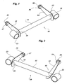
- a link rod according to the invention for connection of the wheel carrier of a motor-vehicle wheel (not shown) with the motor-vehicle structure (also, not shown) through known articulation means, is generally indicated 10.
- the rod 10 comprises an essentially straight, elongated, central body 11 preferably with a hollow cross-section of high torsional stiffness.
- First seats 12, 13 for articulation of the rod to the wheel carrier and the vehicle structure, respectively, are provided at the ends of the central body 11.
- the seats 12, 13 are cylindrical tubular elements attached in per-se-known manner (for example, by welding) to the body 11, with their axes perpendicular to the longitudinal axis of the body 11 and parallel to each other.
- Two flexible elements 14, 15 carrying at their free ends second cylindrical seats 16, 17 for articulation of the rod to the wheel carrier and the vehicle structure, respectively, are secured to the central body 11 close to the seats 12, 13. These elements are chosen to have a high ratio of the stiffness in a given direction to the stiffness in one of the perpendicular directions thereto.
- the flexible elements 14, 15 are advantageously formed as blade-like elements from a sheet of metal or composite material (or of any other material having adequate mechanical properties), so as to be stiff in their middle planes but flexible in the perpendicular directions thereto.
- Each flexible element has a first hole 18, 19 for fitting to the central body 11 and a second hole 20, 21 for connection with the second articulation seat 16, 17.
- each second articulation seat 16, 17 is arranged with its axis substantially perpendicular to the middle plane of the respective flexible element 14, 15.
- the flexible elements 14, 15 may be arranged with their middle planes perpendicular to the longitudinal axis of the body 11 (Figure 1), or inclined thereto (Figure 2, element 16), thereby enabling to set the orientation of the principal stiffnesses of the rod with respect to the pair of members connected thereto.
- a link rod of this type is capable of providing a first translational constraint along the longitudinal axis of the central body 11 and a second rotational constraint about a perpendicular direction to the middle plane of each flexible element 14, 15.
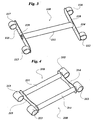
- Figure 3 shows a further link rod 110 according to the invention, capable of providing only a rotational degree of freedom about the longitudinal axis of an essentially straight, elongated, central body 111, preferably with a hollow cross-section of high torsional stiffness.
- a further link rod 110 capable of providing only a rotational degree of freedom about the longitudinal axis of an essentially straight, elongated, central body 111, preferably with a hollow cross-section of high torsional stiffness.
- At the inner and outer ends of the central body 110 there are attached respective central portions of two blade-like flexible elements 114, 115 carrying at their free ends first and second cylindrical seats 112, 116 and 113, 117, respectively, for articulation of the rod to the wheel carrier and the vehicle structure, respectively.
- the seats 112, 116 and 113, 117 are cylindrical tubular elements secured at the outer sides of the respective flexible elements 114 and 115 and having their axes aligned in pair and perpendicular to the longitudinal axis of the body 111.
- the flexible elements 114, 115 are advantageously formed as blade-like elements and have each a hole 118, 119 provided in an intermediate portion thereof for fitting to the central body 111.
- the link rod 110 does not react significantly to the transverse forces transmitted by the wheel carrier through the articulation seats 112, 116.
- the rod 110 controls the rotational degree of freedom about the longitudinal axis of the body 111.
- two connecting rods 210 of conventional shape each comprising an essentially straight, elongated, central body 211 and first and second cylindrical seats 212 and 213 attached at the inner and outer ends of the central body, respectively, for articulation of the connecting rod to the wheel carrier and the vehicle structure, respectively, are arranged parallel to each other and are connected in the region of the seats 212 and 213 by a pair of flexible elements 214 and 215 like those described above.
Landscapes
- Engineering & Computer Science (AREA)
- Mechanical Engineering (AREA)
- Vehicle Body Suspensions (AREA)
- Fluid-Damping Devices (AREA)
- Arrangement Or Mounting Of Propulsion Units For Vehicles (AREA)
- Road Signs Or Road Markings (AREA)
- Load-Engaging Elements For Cranes (AREA)
- Springs (AREA)
Applications Claiming Priority (2)
| Application Number | Priority Date | Filing Date | Title |
|---|---|---|---|
| ITTO20020396 | 2002-05-10 | ||
| IT2002TO000396A ITTO20020396A1 (it) | 2002-05-10 | 2002-05-10 | Asta di collegamento per una sospensione automobilistica. |
Publications (3)
| Publication Number | Publication Date |
|---|---|
| EP1361083A2 true EP1361083A2 (de) | 2003-11-12 |
| EP1361083A3 EP1361083A3 (de) | 2005-05-18 |
| EP1361083B1 EP1361083B1 (de) | 2008-01-09 |
Family
ID=27639066
Family Applications (1)
| Application Number | Title | Priority Date | Filing Date |
|---|---|---|---|
| EP03010359A Expired - Lifetime EP1361083B1 (de) | 2002-05-10 | 2003-05-08 | Verbindungsstange für eine Kraftfahrzeugaufhängung |
Country Status (7)
| Country | Link |
|---|---|
| EP (1) | EP1361083B1 (de) |
| AT (1) | ATE383255T1 (de) |
| BR (1) | BR0301372B1 (de) |
| DE (1) | DE60318516T2 (de) |
| ES (1) | ES2295484T3 (de) |
| IT (1) | ITTO20020396A1 (de) |
| PL (1) | PL207376B1 (de) |
Cited By (4)
| Publication number | Priority date | Publication date | Assignee | Title |
|---|---|---|---|---|
| EP1787833A1 (de) * | 2005-11-22 | 2007-05-23 | Frauenthal Deutschland GmbH | Vierpunktlenker zur Anbindung einer Starrachse an den Rahmen eines Fahrzeuges, insbesondere eines Nutzfahrzeuges |
| WO2007129282A1 (en) * | 2006-05-09 | 2007-11-15 | Sistemi Sospensioni S.P.A. | An arm for a motor vehicle independent suspension and motor vehicle independent suspension comprising the same |
| WO2007113761A3 (en) * | 2006-04-03 | 2007-12-06 | Sistemi Sospensioni Spa | Arm for a motor-vehicle independent suspension and motor-vehicle independent suspension comprising the same |
| JP2016064767A (ja) * | 2014-09-25 | 2016-04-28 | 本田技研工業株式会社 | 揺動アーム |
Families Citing this family (3)
| Publication number | Priority date | Publication date | Assignee | Title |
|---|---|---|---|---|
| DE102012010297A1 (de) * | 2012-05-24 | 2013-11-28 | Piotr Kubinski | Wankbewegungsdämpfer für ein Kraftfahrzeug, schwimmend gelagert und ohne Federelemente |
| DE202013002373U1 (de) | 2013-03-12 | 2013-04-09 | Piotr Kubinski | Vorrichtung zur Selbsterhärtung der Dämpfung eines Wankbewegungsdämpfers für ein Kraftfahrzeug |
| DE202013007733U1 (de) | 2013-08-30 | 2013-10-15 | Piotr Kubinski | Erweiterte Vorrichtung zur Selbsterhärtung der Dämpfung eines Wankbewegungsdämpfers für ein Kraftfahrzeug |
Family Cites Families (12)
| Publication number | Priority date | Publication date | Assignee | Title |
|---|---|---|---|---|
| FR1060549A (fr) * | 1952-07-23 | 1954-04-02 | Renault | Perfectionnements à la suspension des véhicules |
| JPS4819966B1 (de) * | 1968-11-14 | 1973-06-18 | ||
| DE3415869A1 (de) * | 1984-04-28 | 1985-10-31 | Daimler-Benz Ag, 7000 Stuttgart | Vorrichtung zur beeinflussung der wankfederung von fahrzeugen |
| GB2160159A (en) * | 1984-06-01 | 1985-12-18 | Syspal Limited | Rubber spring vehicle suspension system |
| JPS62234705A (ja) * | 1986-04-03 | 1987-10-15 | Toyota Motor Corp | 自動車の懸架装置 |
| FR2624065A1 (fr) * | 1987-12-04 | 1989-06-09 | Renault | Suspension pour vehicule automobile |
| JPH0237008A (ja) * | 1988-07-27 | 1990-02-07 | Mazda Motor Corp | サスペンション装置 |
| DE4107303C2 (de) * | 1991-03-07 | 1994-02-17 | Man Nutzfahrzeuge Ag | Luftgefederte, lenkbare Räder tragende Achse eines Kraftfahrzeuges, insbesondere Niederflurbus |
| US5718445A (en) * | 1994-08-24 | 1998-02-17 | Suspensions, Inc. | Vehicle suspension system |
| SE514129C2 (sv) * | 1998-01-16 | 2001-01-08 | Scania Cv Ab | Krängningshämmare |
| WO2000012330A1 (en) * | 1998-08-27 | 2000-03-09 | Holland Neway International, Inc. | Drive axle suspension |
| ITTO20010843A1 (it) * | 2001-09-03 | 2003-03-03 | Sistemi Sospensioni Spa | Braccio per una sospensione automobilistica a ruote indipendenti e sospensione automobilistica a ruote indipendenti comprendente tale bracci |
-
2002
- 2002-05-10 IT IT2002TO000396A patent/ITTO20020396A1/it unknown
-
2003
- 2003-05-07 BR BRPI0301372-3A patent/BR0301372B1/pt not_active IP Right Cessation
- 2003-05-08 ES ES03010359T patent/ES2295484T3/es not_active Expired - Lifetime
- 2003-05-08 PL PL360010A patent/PL207376B1/pl unknown
- 2003-05-08 EP EP03010359A patent/EP1361083B1/de not_active Expired - Lifetime
- 2003-05-08 AT AT03010359T patent/ATE383255T1/de not_active IP Right Cessation
- 2003-05-08 DE DE60318516T patent/DE60318516T2/de not_active Expired - Lifetime
Non-Patent Citations (1)
| Title |
|---|
| None |
Cited By (7)
| Publication number | Priority date | Publication date | Assignee | Title |
|---|---|---|---|---|
| EP1787833A1 (de) * | 2005-11-22 | 2007-05-23 | Frauenthal Deutschland GmbH | Vierpunktlenker zur Anbindung einer Starrachse an den Rahmen eines Fahrzeuges, insbesondere eines Nutzfahrzeuges |
| WO2007113761A3 (en) * | 2006-04-03 | 2007-12-06 | Sistemi Sospensioni Spa | Arm for a motor-vehicle independent suspension and motor-vehicle independent suspension comprising the same |
| JP2009532273A (ja) * | 2006-04-03 | 2009-09-10 | システミ・ソスペンシオーニ・ソシエタ・ペル・アチオニ | 自動車の独立懸架装置用アーム及びそれを備えた自動車用独立懸架装置 |
| US7832750B2 (en) | 2006-04-03 | 2010-11-16 | Sistemi Sospensioni S.P.A. | Arm for a motor-vehicle independent suspension and motor-vehicle independent suspension comprising the same |
| WO2007129282A1 (en) * | 2006-05-09 | 2007-11-15 | Sistemi Sospensioni S.P.A. | An arm for a motor vehicle independent suspension and motor vehicle independent suspension comprising the same |
| US7845663B2 (en) | 2006-05-09 | 2010-12-07 | Sistemi Sospensioni S.P.A. | Arm for a motor vehicle independent suspension and motor vehicle independent suspension comprising the same |
| JP2016064767A (ja) * | 2014-09-25 | 2016-04-28 | 本田技研工業株式会社 | 揺動アーム |
Also Published As
| Publication number | Publication date |
|---|---|
| DE60318516T2 (de) | 2009-01-08 |
| PL360010A1 (en) | 2003-11-17 |
| ES2295484T3 (es) | 2008-04-16 |
| ATE383255T1 (de) | 2008-01-15 |
| ITTO20020396A0 (it) | 2002-05-10 |
| BR0301372A (pt) | 2004-08-24 |
| EP1361083B1 (de) | 2008-01-09 |
| BR0301372B1 (pt) | 2011-08-09 |
| EP1361083A3 (de) | 2005-05-18 |
| DE60318516D1 (de) | 2008-02-21 |
| ITTO20020396A1 (it) | 2003-11-10 |
| PL207376B1 (pl) | 2010-12-31 |
Similar Documents
| Publication | Publication Date | Title |
|---|---|---|
| US7896372B2 (en) | Suspension device | |
| JP5147829B2 (ja) | 自動車の独立懸架装置用アーム及びそれを備えた自動車用独立懸架装置 | |
| US6860499B2 (en) | Arm for a motor-vehicle independent suspension system and a motor-vehicle independent suspension system comprising the arm | |
| CN102015339B (zh) | 反向转向的车辆后桥 | |
| EP0872367A2 (de) | Hinterradaufhängungsvorrichtung | |
| EP1361083A2 (de) | Verbindungsstange für eine Kraftfahrzeugaufhängung | |
| US20090267312A1 (en) | Vehicle Suspension Device | |
| JP5138676B2 (ja) | 自動車用独立懸架式サスペンション・アーム及びそれを備える自動車用独立懸架式サスペンション | |
| EP1827878B1 (de) | Unabhängige aufhängung für ein kraftfahrzeug | |
| EP1361084A2 (de) | Montageanordnung für einen Radträger eines Kraftfahrzeugs | |
| US7506882B2 (en) | Motor-vehicle independent suspension | |
| JP3633292B2 (ja) | サスペンション装置 | |
| US20020047244A1 (en) | Rear axle for a motor vehicle | |
| EP0971152A2 (de) | Rückhaltungsglied | |
| JPS6121803A (ja) | 車両用懸架装置 | |
| JPH11170830A (ja) | 操舵輪用懸架装置 | |
| GB2339260A (en) | Restraining link |
Legal Events
| Date | Code | Title | Description |
|---|---|---|---|
| PUAI | Public reference made under article 153(3) epc to a published international application that has entered the european phase |
Free format text: ORIGINAL CODE: 0009012 |
|
| AK | Designated contracting states |
Kind code of ref document: A2 Designated state(s): AT BE BG CH CY CZ DE DK EE ES FI FR GB GR HU IE IT LI LU MC NL PT RO SE SI SK TR |
|
| AX | Request for extension of the european patent |
Extension state: AL LT LV MK |
|
| PUAL | Search report despatched |
Free format text: ORIGINAL CODE: 0009013 |
|
| AK | Designated contracting states |
Kind code of ref document: A3 Designated state(s): AT BE BG CH CY CZ DE DK EE ES FI FR GB GR HU IE IT LI LU MC NL PT RO SE SI SK TR |
|
| AX | Request for extension of the european patent |
Extension state: AL LT LV MK |
|
| 17P | Request for examination filed |
Effective date: 20051115 |
|
| AKX | Designation fees paid |
Designated state(s): AT BE BG CH CY CZ DE DK EE ES FI FR GB GR HU IE IT LI LU MC NL PT RO SE SI SK TR |
|
| GRAP | Despatch of communication of intention to grant a patent |
Free format text: ORIGINAL CODE: EPIDOSNIGR1 |
|
| RAP1 | Party data changed (applicant data changed or rights of an application transferred) |
Owner name: SISTEMI SOSPENSIONI S.P.A. |
|
| GRAS | Grant fee paid |
Free format text: ORIGINAL CODE: EPIDOSNIGR3 |
|
| GRAA | (expected) grant |
Free format text: ORIGINAL CODE: 0009210 |
|
| AK | Designated contracting states |
Kind code of ref document: B1 Designated state(s): AT BE BG CH CY CZ DE DK EE ES FI FR GB GR HU IE IT LI LU MC NL PT RO SE SI SK TR |
|
| REG | Reference to a national code |
Ref country code: GB Ref legal event code: FG4D |
|
| REG | Reference to a national code |
Ref country code: CH Ref legal event code: EP |
|
| REG | Reference to a national code |
Ref country code: IE Ref legal event code: FG4D |
|
| REF | Corresponds to: |
Ref document number: 60318516 Country of ref document: DE Date of ref document: 20080221 Kind code of ref document: P |
|
| REG | Reference to a national code |
Ref country code: ES Ref legal event code: FG2A Ref document number: 2295484 Country of ref document: ES Kind code of ref document: T3 |
|
| REG | Reference to a national code |
Ref country code: HU Ref legal event code: AG4A Ref document number: E002769 Country of ref document: HU |
|
| PG25 | Lapsed in a contracting state [announced via postgrant information from national office to epo] |
Ref country code: SI Free format text: LAPSE BECAUSE OF FAILURE TO SUBMIT A TRANSLATION OF THE DESCRIPTION OR TO PAY THE FEE WITHIN THE PRESCRIBED TIME-LIMIT Effective date: 20080109 Ref country code: NL Free format text: LAPSE BECAUSE OF FAILURE TO SUBMIT A TRANSLATION OF THE DESCRIPTION OR TO PAY THE FEE WITHIN THE PRESCRIBED TIME-LIMIT Effective date: 20080109 |
|
| NLV1 | Nl: lapsed or annulled due to failure to fulfill the requirements of art. 29p and 29m of the patents act | ||
| ET | Fr: translation filed | ||
| PG25 | Lapsed in a contracting state [announced via postgrant information from national office to epo] |
Ref country code: LI Free format text: LAPSE BECAUSE OF FAILURE TO SUBMIT A TRANSLATION OF THE DESCRIPTION OR TO PAY THE FEE WITHIN THE PRESCRIBED TIME-LIMIT Effective date: 20080109 Ref country code: CH Free format text: LAPSE BECAUSE OF FAILURE TO SUBMIT A TRANSLATION OF THE DESCRIPTION OR TO PAY THE FEE WITHIN THE PRESCRIBED TIME-LIMIT Effective date: 20080109 Ref country code: FI Free format text: LAPSE BECAUSE OF FAILURE TO SUBMIT A TRANSLATION OF THE DESCRIPTION OR TO PAY THE FEE WITHIN THE PRESCRIBED TIME-LIMIT Effective date: 20080109 |
|
| REG | Reference to a national code |
Ref country code: CH Ref legal event code: PL |
|
| PG25 | Lapsed in a contracting state [announced via postgrant information from national office to epo] |
Ref country code: AT Free format text: LAPSE BECAUSE OF FAILURE TO SUBMIT A TRANSLATION OF THE DESCRIPTION OR TO PAY THE FEE WITHIN THE PRESCRIBED TIME-LIMIT Effective date: 20080109 Ref country code: BG Free format text: LAPSE BECAUSE OF FAILURE TO SUBMIT A TRANSLATION OF THE DESCRIPTION OR TO PAY THE FEE WITHIN THE PRESCRIBED TIME-LIMIT Effective date: 20080409 |
|
| PG25 | Lapsed in a contracting state [announced via postgrant information from national office to epo] |
Ref country code: PT Free format text: LAPSE BECAUSE OF FAILURE TO SUBMIT A TRANSLATION OF THE DESCRIPTION OR TO PAY THE FEE WITHIN THE PRESCRIBED TIME-LIMIT Effective date: 20080609 Ref country code: BE Free format text: LAPSE BECAUSE OF FAILURE TO SUBMIT A TRANSLATION OF THE DESCRIPTION OR TO PAY THE FEE WITHIN THE PRESCRIBED TIME-LIMIT Effective date: 20080109 |
|
| PG25 | Lapsed in a contracting state [announced via postgrant information from national office to epo] |
Ref country code: SK Free format text: LAPSE BECAUSE OF FAILURE TO SUBMIT A TRANSLATION OF THE DESCRIPTION OR TO PAY THE FEE WITHIN THE PRESCRIBED TIME-LIMIT Effective date: 20080109 Ref country code: DK Free format text: LAPSE BECAUSE OF FAILURE TO SUBMIT A TRANSLATION OF THE DESCRIPTION OR TO PAY THE FEE WITHIN THE PRESCRIBED TIME-LIMIT Effective date: 20080109 Ref country code: SE Free format text: LAPSE BECAUSE OF FAILURE TO SUBMIT A TRANSLATION OF THE DESCRIPTION OR TO PAY THE FEE WITHIN THE PRESCRIBED TIME-LIMIT Effective date: 20080409 |
|
| PLBE | No opposition filed within time limit |
Free format text: ORIGINAL CODE: 0009261 |
|
| STAA | Information on the status of an ep patent application or granted ep patent |
Free format text: STATUS: NO OPPOSITION FILED WITHIN TIME LIMIT |
|
| PG25 | Lapsed in a contracting state [announced via postgrant information from national office to epo] |
Ref country code: RO Free format text: LAPSE BECAUSE OF FAILURE TO SUBMIT A TRANSLATION OF THE DESCRIPTION OR TO PAY THE FEE WITHIN THE PRESCRIBED TIME-LIMIT Effective date: 20080109 |
|
| 26N | No opposition filed |
Effective date: 20081010 |
|
| PG25 | Lapsed in a contracting state [announced via postgrant information from national office to epo] |
Ref country code: MC Free format text: LAPSE BECAUSE OF NON-PAYMENT OF DUE FEES Effective date: 20080531 |
|
| PG25 | Lapsed in a contracting state [announced via postgrant information from national office to epo] |
Ref country code: EE Free format text: LAPSE BECAUSE OF FAILURE TO SUBMIT A TRANSLATION OF THE DESCRIPTION OR TO PAY THE FEE WITHIN THE PRESCRIBED TIME-LIMIT Effective date: 20080109 |
|
| PG25 | Lapsed in a contracting state [announced via postgrant information from national office to epo] |
Ref country code: IE Free format text: LAPSE BECAUSE OF NON-PAYMENT OF DUE FEES Effective date: 20080508 |
|
| PG25 | Lapsed in a contracting state [announced via postgrant information from national office to epo] |
Ref country code: CY Free format text: LAPSE BECAUSE OF FAILURE TO SUBMIT A TRANSLATION OF THE DESCRIPTION OR TO PAY THE FEE WITHIN THE PRESCRIBED TIME-LIMIT Effective date: 20080109 |
|
| PG25 | Lapsed in a contracting state [announced via postgrant information from national office to epo] |
Ref country code: LU Free format text: LAPSE BECAUSE OF NON-PAYMENT OF DUE FEES Effective date: 20080508 |
|
| PG25 | Lapsed in a contracting state [announced via postgrant information from national office to epo] |
Ref country code: GR Free format text: LAPSE BECAUSE OF FAILURE TO SUBMIT A TRANSLATION OF THE DESCRIPTION OR TO PAY THE FEE WITHIN THE PRESCRIBED TIME-LIMIT Effective date: 20080410 |
|
| PGFP | Annual fee paid to national office [announced via postgrant information from national office to epo] |
Ref country code: ES Payment date: 20150506 Year of fee payment: 13 Ref country code: GB Payment date: 20150424 Year of fee payment: 13 Ref country code: CZ Payment date: 20150424 Year of fee payment: 13 |
|
| PGFP | Annual fee paid to national office [announced via postgrant information from national office to epo] |
Ref country code: HU Payment date: 20150528 Year of fee payment: 13 |
|
| REG | Reference to a national code |
Ref country code: FR Ref legal event code: PLFP Year of fee payment: 14 |
|
| GBPC | Gb: european patent ceased through non-payment of renewal fee |
Effective date: 20160508 |
|
| PG25 | Lapsed in a contracting state [announced via postgrant information from national office to epo] |
Ref country code: CZ Free format text: LAPSE BECAUSE OF NON-PAYMENT OF DUE FEES Effective date: 20160508 |
|
| REG | Reference to a national code |
Ref country code: FR Ref legal event code: PLFP Year of fee payment: 15 |
|
| PG25 | Lapsed in a contracting state [announced via postgrant information from national office to epo] |
Ref country code: HU Free format text: LAPSE BECAUSE OF NON-PAYMENT OF DUE FEES Effective date: 20160509 |
|
| PG25 | Lapsed in a contracting state [announced via postgrant information from national office to epo] |
Ref country code: GB Free format text: LAPSE BECAUSE OF NON-PAYMENT OF DUE FEES Effective date: 20160508 |
|
| REG | Reference to a national code |
Ref country code: FR Ref legal event code: PLFP Year of fee payment: 16 |
|
| PG25 | Lapsed in a contracting state [announced via postgrant information from national office to epo] |
Ref country code: ES Free format text: LAPSE BECAUSE OF NON-PAYMENT OF DUE FEES Effective date: 20160509 |
|
| REG | Reference to a national code |
Ref country code: ES Ref legal event code: FD2A Effective date: 20181204 |
|
| PGFP | Annual fee paid to national office [announced via postgrant information from national office to epo] |
Ref country code: TR Payment date: 20190430 Year of fee payment: 17 |
|
| PGFP | Annual fee paid to national office [announced via postgrant information from national office to epo] |
Ref country code: DE Payment date: 20210421 Year of fee payment: 19 Ref country code: FR Payment date: 20210421 Year of fee payment: 19 Ref country code: IT Payment date: 20210422 Year of fee payment: 19 |
|
| PG25 | Lapsed in a contracting state [announced via postgrant information from national office to epo] |
Ref country code: TR Free format text: LAPSE BECAUSE OF NON-PAYMENT OF DUE FEES Effective date: 20200508 |
|
| REG | Reference to a national code |
Ref country code: DE Ref legal event code: R119 Ref document number: 60318516 Country of ref document: DE |
|
| PG25 | Lapsed in a contracting state [announced via postgrant information from national office to epo] |
Ref country code: FR Free format text: LAPSE BECAUSE OF NON-PAYMENT OF DUE FEES Effective date: 20220531 |
|
| PG25 | Lapsed in a contracting state [announced via postgrant information from national office to epo] |
Ref country code: DE Free format text: LAPSE BECAUSE OF NON-PAYMENT OF DUE FEES Effective date: 20221201 |
|
| PG25 | Lapsed in a contracting state [announced via postgrant information from national office to epo] |
Ref country code: IT Free format text: LAPSE BECAUSE OF NON-PAYMENT OF DUE FEES Effective date: 20220508 |