EP1361078A1 - Pannenlauffähiger Fahrzeugluftreifen - Google Patents
Pannenlauffähiger Fahrzeugluftreifen Download PDFInfo
- Publication number
- EP1361078A1 EP1361078A1 EP03006611A EP03006611A EP1361078A1 EP 1361078 A1 EP1361078 A1 EP 1361078A1 EP 03006611 A EP03006611 A EP 03006611A EP 03006611 A EP03006611 A EP 03006611A EP 1361078 A1 EP1361078 A1 EP 1361078A1
- Authority
- EP
- European Patent Office
- Prior art keywords
- reinforcing element
- vehicle tire
- pneumatic vehicle
- tire according
- curvature
- Prior art date
- Legal status (The legal status is an assumption and is not a legal conclusion. Google has not performed a legal analysis and makes no representation as to the accuracy of the status listed.)
- Granted
Links
- 239000000463 material Substances 0.000 claims abstract description 6
- 239000011324 bead Substances 0.000 claims abstract description 5
- 230000003014 reinforcing effect Effects 0.000 claims description 49
- 230000007704 transition Effects 0.000 claims description 8
- 230000015556 catabolic process Effects 0.000 claims description 6
- 229920001971 elastomer Polymers 0.000 claims description 5
- 239000000203 mixture Substances 0.000 claims description 4
- 210000004072 lung Anatomy 0.000 claims 1
- 230000013011 mating Effects 0.000 claims 1
- 230000002787 reinforcement Effects 0.000 abstract description 9
- 229920005549 butyl rubber Polymers 0.000 description 3
- 238000004519 manufacturing process Methods 0.000 description 3
- 239000004760 aramid Substances 0.000 description 2
- 229920003235 aromatic polyamide Polymers 0.000 description 2
- 238000005452 bending Methods 0.000 description 2
- 150000001875 compounds Chemical class 0.000 description 2
- 210000000629 knee joint Anatomy 0.000 description 2
- 230000007306 turnover Effects 0.000 description 2
- 229920001875 Ebonite Polymers 0.000 description 1
- PEDCQBHIVMGVHV-UHFFFAOYSA-N Glycerine Chemical compound OCC(O)CO PEDCQBHIVMGVHV-UHFFFAOYSA-N 0.000 description 1
- 239000004677 Nylon Substances 0.000 description 1
- 229910000831 Steel Inorganic materials 0.000 description 1
- 238000005299 abrasion Methods 0.000 description 1
- 230000008859 change Effects 0.000 description 1
- 230000006378 damage Effects 0.000 description 1
- 230000000694 effects Effects 0.000 description 1
- 238000002474 experimental method Methods 0.000 description 1
- 230000017525 heat dissipation Effects 0.000 description 1
- 230000006872 improvement Effects 0.000 description 1
- 238000007373 indentation Methods 0.000 description 1
- 229920001778 nylon Polymers 0.000 description 1
- 238000013021 overheating Methods 0.000 description 1
- 229920000728 polyester Polymers 0.000 description 1
- 238000003825 pressing Methods 0.000 description 1
- 230000000717 retained effect Effects 0.000 description 1
- 238000009991 scouring Methods 0.000 description 1
- 239000010959 steel Substances 0.000 description 1
- 239000000725 suspension Substances 0.000 description 1
Images

Classifications
-
- B—PERFORMING OPERATIONS; TRANSPORTING
- B60—VEHICLES IN GENERAL
- B60C—VEHICLE TYRES; TYRE INFLATION; TYRE CHANGING; CONNECTING VALVES TO INFLATABLE ELASTIC BODIES IN GENERAL; DEVICES OR ARRANGEMENTS RELATED TO TYRES
- B60C15/00—Tyre beads, e.g. ply turn-up or overlap
- B60C15/0009—Tyre beads, e.g. ply turn-up or overlap features of the carcass terminal portion
- B60C15/0036—Tyre beads, e.g. ply turn-up or overlap features of the carcass terminal portion with high ply turn-up, i.e. folded around the bead core and terminating radially above the point of maximum section width
- B60C15/0045—Tyre beads, e.g. ply turn-up or overlap features of the carcass terminal portion with high ply turn-up, i.e. folded around the bead core and terminating radially above the point of maximum section width with ply turn-up up to the belt edges, i.e. folded around the bead core and extending to the belt edges
-
- B—PERFORMING OPERATIONS; TRANSPORTING
- B60—VEHICLES IN GENERAL
- B60C—VEHICLE TYRES; TYRE INFLATION; TYRE CHANGING; CONNECTING VALVES TO INFLATABLE ELASTIC BODIES IN GENERAL; DEVICES OR ARRANGEMENTS RELATED TO TYRES
- B60C11/00—Tyre tread bands; Tread patterns; Anti-skid inserts
- B60C11/01—Shape of the shoulders between tread and sidewall, e.g. rounded, stepped or cantilevered
-
- B—PERFORMING OPERATIONS; TRANSPORTING
- B60—VEHICLES IN GENERAL
- B60C—VEHICLE TYRES; TYRE INFLATION; TYRE CHANGING; CONNECTING VALVES TO INFLATABLE ELASTIC BODIES IN GENERAL; DEVICES OR ARRANGEMENTS RELATED TO TYRES
- B60C13/00—Tyre sidewalls; Protecting, decorating, marking, or the like, thereof
- B60C13/003—Tyre sidewalls; Protecting, decorating, marking, or the like, thereof characterised by sidewall curvature
- B60C13/004—Tyre sidewalls; Protecting, decorating, marking, or the like, thereof characterised by sidewall curvature of the internal side of the tyre
-
- B—PERFORMING OPERATIONS; TRANSPORTING
- B60—VEHICLES IN GENERAL
- B60C—VEHICLE TYRES; TYRE INFLATION; TYRE CHANGING; CONNECTING VALVES TO INFLATABLE ELASTIC BODIES IN GENERAL; DEVICES OR ARRANGEMENTS RELATED TO TYRES
- B60C17/00—Tyres characterised by means enabling restricted operation in damaged or deflated condition; Accessories therefor
- B60C17/0009—Tyres characterised by means enabling restricted operation in damaged or deflated condition; Accessories therefor comprising sidewall rubber inserts, e.g. crescent shaped inserts
-
- B—PERFORMING OPERATIONS; TRANSPORTING
- B60—VEHICLES IN GENERAL
- B60C—VEHICLE TYRES; TYRE INFLATION; TYRE CHANGING; CONNECTING VALVES TO INFLATABLE ELASTIC BODIES IN GENERAL; DEVICES OR ARRANGEMENTS RELATED TO TYRES
- B60C17/00—Tyres characterised by means enabling restricted operation in damaged or deflated condition; Accessories therefor
- B60C17/08—Means facilitating folding of sidewalls, e.g. run-flat sidewalls
-
- B—PERFORMING OPERATIONS; TRANSPORTING
- B60—VEHICLES IN GENERAL
- B60C—VEHICLE TYRES; TYRE INFLATION; TYRE CHANGING; CONNECTING VALVES TO INFLATABLE ELASTIC BODIES IN GENERAL; DEVICES OR ARRANGEMENTS RELATED TO TYRES
- B60C3/00—Tyres characterised by the transverse section
- B60C3/04—Tyres characterised by the transverse section characterised by the relative dimensions of the section, e.g. low profile
Definitions
- the invention relates to a pneumatic vehicle tire with a tread, one of a Variety of reinforcements formed radial carcass, which extends from the crown area extends radially inward over two side wall parts and on cores of beads is anchored, and a belt of at least two layers of cord, which is between the Tread and the crown area of the radial carcass is embedded, being in the Sidewall parts each have at least one stiffening element to enable one Breakdown is embedded, which is stiffer than the surrounding side wall part.
- Such a pneumatic vehicle tire has one that is not suitable for puncture running Tire on a thickened sidewall and is commonly referred to as “self-supporting tire (SST) "or also known as” Run-flat tire “(RFT)”.
- SST self-supporting tire
- RFT Run-flat tire
- the Sidewall reinforcing reinforcement element in the shape of a crescent moon and is in the upper region of the side wall arranged axially on the inside so that the convex curvature of the Reinforcing element of the curvature of the transition area from the shoulder to the side wall and follows the curvature of the side wall itself.
- the crescent-shaped reinforcement elements follow in their Outer contour of the toroidal contour of the tire, in particular in the area of Shoulder and sidewall.
- Such a configuration is obvious and is pressing to the expert, since the toroidal shape of the tire appears to be predetermined and the manufacture of such a tire with the contour of the tire following the shape of the reinforcement elements to cause the least manufacturing-related problems seems.
- the invention was therefore based on the object, a pneumatic vehicle tire of the beginning to create described type, which in the event of a breakdown, lower loads subject than with conventional solutions.
- the side wall parts and the reinforcing element of the pneumatic vehicle tire has a wavy shape Have curvature, such that a center line of the reinforcing element has at least one reversal of curvature, the reinforcing element in has a convex-concave profile in a central region, the convex curvature is directed axially inward.
- the pneumatic vehicle tire according to the invention is therefore not toroidal, but has one Sidewall with an approximately S-shaped course. This leads to surprising effects with which the task can be solved.
- the pneumatic vehicle tire according to the invention therefore bulges inside and not outside.
- This enables, in particular, the radius in the To keep the transition area from the tread to the side wall part relatively large
- the insert By designing the insert with at least a reversal of the curvature creates a kind of knee joint, which ensures that the tire bulges axially inwards. Accordingly, inner ones no longer move Areas of the tire move towards each other and, in extreme cases, touch each other outer areas of the tire towards one another, in particular the shoulder area of the tire Tread in the direction of a rubbing strake of the lower side wall area. This Areas, however, are to be considered much less critically than those with regard to frictional forces Inner layer of butyl rubber, since these areas are made of a hard rubber mixture can be produced.
- the pneumatic vehicle tire according to the invention also has advantages in normal driving compared to conventional solutions. Because the suspension comfort is usual SST tires are significantly worse than normal tires that are not suitable for flat tires Tires. The thickened sidewall of SST tires allows the tire to deflect hardly to. However, the pneumatic vehicle tire according to the invention leaves a certain degree to deflection because the reversal of curvature serving as a knee joint is a Allows flexibility of the side wall.
- the Radial carcass is guided around the cores from axially inside to axially outside, with a End of the radial carcass is covered by a lower cord layer of the belt.
- the so-called layer turnover of the carcass ends around the core below the Belt, which helps the belt to secure the layer turn.
- the radial carcass consists of two layers, which are guided around the cores from axially inside to axially outside, with here it can be provided that at least one end of a position of the radial carcass in one middle or an upper region of the side wall part is arranged.
- the carcass can therefore be double-layered, with the height of the layer turnover being the same in both layers or can be different. A lower axial height is preferred outer one of the layers.
- a End of the reinforcing element is covered by at least one cord layer of the belt.
- the reinforcing element is integral with an over the core arranged apex is connected, the reinforcing element and the apex being made of consist of the same material.
- the reinforcing element and the apex have two are separate components, in which case it can further be provided that a lower end of the Reinforcing element and an upper end of the apex each as a wedge with each other matching wedge surfaces are formed.
- the Reinforcing element essentially comprises three areas, namely a middle Area with the axially inward convex curvature, an upper area and a lower area, with a transition from the middle area to the lower area and to the top by two reversals of the midline curvature Reinforcing element is formed. It can further be provided that the upper one Area of the reinforcing element is concave-convex, such that a convex curved surface is directed axially outwards.
- the radius R of the concave, axially directed arc of the upper region of the reinforcing element in normal operation between 30 and 40 mm and in the emergency running condition between 5 and 12 mm preferably is between 8 and 12 mm, causing buckling stresses in this critical Area can be reduced to a minimum.
- the Reinforcing element consists of a silica-rubber mixture. It has been practical Experiments have shown that such a mixture, which is otherwise only available for Tread compounds are used, particularly good properties in terms of Has durability of the reinforcing element.
- the side wall part at its lowest in the area of the first reversal of curvature Has thickness. This measure promotes easy and stress-free bending of the Side wall axially inside.
- the curvature of the reinforcing element between the reversals of curvature is stronger when the vehicle tire is depressurized than when inflated.
- the reinforcing element is and correspondingly, the side wall part after the completion of the tire relatively strong inwards curved and without tension. Inflating the tire to approx. 2-3 bar causes a Bulging the side wall outwards. If an emergency occurs, the side wall turns in their original, tension-free position. This is compared to the traditional ones Solutions advantageous because there are tensions caused by bending against the natural Alignment of the reinforcing element occur and wear of the Promote reinforcing element.
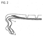
- Figures 1 and 2 is a first embodiment of an inventive Pneumatic vehicle tire 1 shown in radial section, the figures being the left half of a otherwise show symmetrical tire on average through the tire zen Z-Z '.
- the pneumatic vehicle tire 1 has a tread 2 and one radial carcass 3 formed from a plurality of reinforcing members.
- the Strength members of the radial carcass 3 can be cords, in particular polyester cords, but also cords made of other materials such as aramid or steel can be used as well as hybrid cords made of nylon and aramid.
- the radial carcass 3 extends itself from the apex area of the pneumatic vehicle tire 1 via two side wall parts, one of which in the figures, a left side wall part 4 is shown, radially inwards and is on Cores 5 anchored by beads 6.
- a belt 7 is arranged on the tread 2, which in the exemplary embodiment shown consists of two cord layers 8, 9.
- the belt 7 is reinforced with a bandage 10, which in the exemplary embodiment shown, from a lower layer 11 and from an upper layer 12 consists of both circumferentially on the belt during the Manufacturing process are spooled.
- a rubber cushion 13 arranged, which for a distance between the belt layers in their Edge area provides.
- the tread 2 goes on its surface 14 through a shoulder region 15 in the Side wall part 4, which at its lower end before the transition into the bead 6 has a rubbing strake 16 or rim protection rib. But it is also possible on this to renounce.
- the carcass 3 is guided around the core 5 and an apex 17 such that one end 18 the radial carcass 3 ends approximately below the belt 7 or the bandage 10.
- a den Layer change forming, axially outer region 19 of the radial carcass 3 closes between itself and an axially inner region 20 of the radial carcass, a reinforcing element 21 which serves to drive even when the pneumatic vehicle tire 1 is depressurized enable at least over a certain distance.
- a center line M of the reinforcing element 21 has one Curvature, which initially follows the curvature of the shoulder region 15 and approximately has a first curvature reversal 22 in the upper third of the side wall part 4. From the first curvature reversal 22 to a second curvature reversal 23 the arc of the center line M runs axially inward.
- reinforcing element 21 In the central area B of the Reinforcing element 21, that is, approximately between the first curvature reversal 22 and the second curvature reversal 23 has the reinforcing element 21 convex-concave profile, the convex curvature 24 of which is directed axially inwards.
- reinforcing element 21 and side wall 3 have an axial direction in this area outside a concave indentation 25.
- the reinforcing element 21 is designed as a wedge, which is a Wedge surface, which with an appropriately designed wedge surface of the apex 17th corresponds. Unlike shown in Figure 1, it is also possible to use reinforcing element 21 and Apex 17 in one piece.
- R is the radius of the arc of the reinforcing element 21 in the upper region A or the radius of the inner area of the pneumatic vehicle tire 1 in the transition area Shoulder / tread indicated. In the normal state, than in the inflated state, the radius is about 30 - 40 mm.
- the pneumatic vehicle tire 1 from FIG. 1 is under load in the deflated state shown, i.e. in a state that corresponds to the breakdown. It can be seen in particular that the side wall part 4 and the reinforcing element 21 extend axially inwards have dented
- the radius r here is approximately between 8 and 12 mm, but can be in In extreme cases, it can be as little as 5 mm.
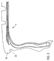
- FIG 3 is a second embodiment of an inventive Pneumatic vehicle tire 1 shown, which is different from that shown in Figures 1 and 2 Pneumatic vehicle tire 1 differs in that its shoulder to enlarge the Footprint, especially in the event of a breakdown, further over the belt edge area has moved out. Below the shoulder 15 is a groove 26 which is the Heat dissipation of heat generated in the event of a breakdown serves.
Landscapes
- Engineering & Computer Science (AREA)
- Mechanical Engineering (AREA)
- Tires In General (AREA)
Abstract
Description
- Fig. 1
- eine Teilansicht eines ersten Ausführungsbeispiels des erfindungsgemäßen Fahrzeugluftreifens mit Radialschnitt
- Fig. 2
- den Reifen aus Figur 1 unter Belastung
- Fig. 3
- eine Teilansicht eines zweiten Ausführungsbeispiels eines erfindungsgemäßen Fahrzeugluftreifens in Radialschnitt.
Claims (15)
- Fahrzeugluftreifen (1) mit einem Laufstreifen (2), einer aus einer Vielzahl von Festigkeitsträgern gebildeten Radialkarkasse (3), die sich vom Scheitelbereich über zwei Seitenwandteile (4) nach radial innen erstreckt und an Kernen (5) von Wülsten (6) verankert ist, und einem Gürtel (7) aus wenigstens zwei Cordlagen (8, 9), welcher zwischen dem Laufstreifen (2) und dem Scheitelbereich der Radialkarkasse (3) eingebettet ist, wobei in den Seitenwandteilen (4) jeweils wenigstens ein Verstärkungselement (21) zur Ermöglichung einer Pannenfahrt eingebettet ist, welches steifer als das sie umgebende Seitenwandteil (4) ist, dadurch gekennzeichnet, dass die Seitenwandteile (4) und das Verstärkungselement einen wellenförmigen Krümmungsverlauf aufweisen, derart, dass eine Mittellinie (M) des Verstärkungselementes (21) wenigstens eine Krümmungsumkehrung (22) aufweist, wobei das Verstärkungselement (21) in einem mittleren Bereich (B) ein konvexkonkaves Profil aufweist, dessen kovexe Wölbung (24) nach axial innen gerichtet ist.
- Fahrzeugluftreifen nach Anspruch 1, dadurch gekennzeichnet, dass die Radialkarkasse (3) um die Kerne (5) von axial innen nach axial außen herumgeführt ist, wobei ein Ende (18) der Radialkarkasse (3) von einer unteren Cordlage (8) des Gürtels (7) abgedeckt ist.
- Fahrzeugluftreifen nach Anspruch 2, dadurch gekennzeichnet, dass die Radialkarkasse (3) aus zwei Lagen besteht, welche um die Kerne (5) von axial innen nach axial außen herumgeführt sind.
- Fahrzeugluftreifen nach Anspruch 3, dadurch gekennzeichnet, dass wenigstens ein Ende (18) einer Lage der Radialkarkasse (3) in einem mittleren (B) oder einem oberen Bereich (A) des Seitenwandteils (4) angeordnet ist.
- Fahrzeugluftreifen nach einem der Ansprüche 1 - 4, dadurch gekennzeichnet, dass ein Ende des Verstärkungselements (21) von wenigstens einer Cordlage (8; 9) des Gürtels (7) abgedeckt ist.
- Fahrzeugluftreifen nach einem der Ansprüche 1 - 5, dadurch gekennzeichnet, dass das Verstärkungselement (21) einstückig mit einem über dem Kern (5) angeordneten Apex (17) verbunden ist.
- Fahrzeugluftreifen nach einem der Ansprüche 1 - 5, dadurch gekennzeichnet, dass das Verstärkungselement (21) und der Apex (17) zwei separate Bauteile sind.
- Fahrzeugluftreifen nach einem der Ansprüche 1 - 7, dadurch gekennzeichnet, dass Verstärkungselement (21) und Apex (17) aus dem gleichen Material bestehen.
- Fahrzeugluftreifen nach Anspruch 7, dadurch gekennzeichnet, dass ein unteres Ende des Verstärkungselements (21) und ein oberes Ende des Apex (17) jeweils als Keil mit zueinander passenden Keilflächen ausgebildet sind.
- Fahrzeugluftreifen nach einem der Ansprüche 1 - 9, dadurch gekennzeichnet, dass das Verstärkungselement (21) im wesentlichen drei Bereiche (A, B, C) umfaßt, nämlich einen mittleren Bereich (B) mit der nach axial innen gerichteten konvexen Wölbung (24), einen oberen Bereich (A) und einem unteren Bereich (C), wobei ein Übergang des mittleren Bereichs (B) zum unteren Bereich (C) und zum oberen Bereich (A) durch zwei Krümmungsumkehrungen (22, 23) der Mittellinie (M) des Verstärkungselements (21) gebildet ist.
- Fahrzeugluftreifen nach Anspruch 10, dadurch gekennzeichnet, dass der obere Bereich (A) des Verstärkungselements (21) konkavkonvex gewölbt ist, derart, dass eine konvex gebogene Oberfläche nach axial außen gerichtet ist.
- Fahrzeugluftreifen nach Anspruch 11, dadurch gekennzeichnet, dass der Radius (r) des konkaven, nach axial innen gerichteten Bogens des oberen Bereich (A) des Verstärkungselements (21) im Normalbetrieb zwischen 30 und 40 mm und im Notlaufzustand zwischen 5 und 12 mm, vorzugsweise zwischen 8 und 12 mm beträgt.
- Fahrzeugluftreifen nach einem der Ansprüche 1 - 12, dadurch gekennzeichnet, dass das Verstärkungselement (21) aus einer Silica-Gummimischung besteht.
- Fahrzeugluftreifen nach einem der Ansprüche 1 - 13, dadurch gekennzeichnet, dass das Seitenwandteil (4) etwa im Bereich der ersten Krümmungsumkehrung (22) seine geringste Dicke aufweist.
- Fahrzeugluftreifen nach einem der Ansprüche 1 - 14, dadurch gekennzeichnet, dass die Krümmung des Verstärkungselements (21) zwischen den, Krümmungsumkehrungen (22, 23) im drucklosen Zustand des Fahrzeugluftreifens stärker ist als im aufgepumpten Zustand.
Applications Claiming Priority (2)
| Application Number | Priority Date | Filing Date | Title |
|---|---|---|---|
| DE10221078 | 2002-05-11 | ||
| DE10221078A DE10221078A1 (de) | 2002-05-11 | 2002-05-11 | Pannenlauffähiger Fahrzeugluftreifen |
Publications (2)
| Publication Number | Publication Date |
|---|---|
| EP1361078A1 true EP1361078A1 (de) | 2003-11-12 |
| EP1361078B1 EP1361078B1 (de) | 2005-01-12 |
Family
ID=29225156
Family Applications (1)
| Application Number | Title | Priority Date | Filing Date |
|---|---|---|---|
| EP03006611A Expired - Lifetime EP1361078B1 (de) | 2002-05-11 | 2003-03-25 | Pannenlauffähiger Fahrzeugluftreifen |
Country Status (2)
| Country | Link |
|---|---|
| EP (1) | EP1361078B1 (de) |
| DE (2) | DE10221078A1 (de) |
Cited By (5)
| Publication number | Priority date | Publication date | Assignee | Title |
|---|---|---|---|---|
| DE102004031811A1 (de) * | 2004-07-01 | 2006-02-16 | Continental Aktiengesellschaft | Notlauffähiger Fahrzeugluftreifen und Verfahren zu dessen Herstellung |
| FR2997653A1 (fr) * | 2012-11-07 | 2014-05-09 | Otico | Pneumatique semi-creux a profil ameliore et organe roulant equipe de tels pneumatiques |
| JP2014118083A (ja) * | 2012-12-18 | 2014-06-30 | Bridgestone Corp | ランフラットタイヤ |
| CN106994868A (zh) * | 2017-04-01 | 2017-08-01 | 江苏奔腾橡胶制品有限公司 | 一种胎侧凹陷式防爆轮胎 |
| EP3240700A4 (de) * | 2014-12-30 | 2018-08-08 | Bridgestone Americas Tire Operations, LLC | Reifen mit konkaven seitenwänden |
Families Citing this family (4)
| Publication number | Priority date | Publication date | Assignee | Title |
|---|---|---|---|---|
| DE102004007601A1 (de) * | 2004-02-17 | 2005-09-01 | Schwarz, Günter | S.B.Z.-Rad / S.B.Z.-Rad-System |
| DE102005044354A1 (de) * | 2005-09-16 | 2006-03-30 | Schwarz, Günter | Pannless Fahrzeugreifen SBZ |
| EP3461268A4 (de) * | 2016-09-25 | 2019-07-17 | Galileo Wheel Ltd. | Luftreifen mit ringförmiger seitenwandwölbung |
| DE102017222117A1 (de) | 2017-12-07 | 2019-06-13 | Continental Reifen Deutschland Gmbh | Fahrzeugluftreifen mit einer Felgenschutzrippe |
Citations (5)
| Publication number | Priority date | Publication date | Assignee | Title |
|---|---|---|---|---|
| EP0475258A1 (de) * | 1990-09-14 | 1992-03-18 | PIRELLI COORDINAMENTO PNEUMATICI S.p.A. | Selbsttragende Karkasse für Motorfahrzeugreifen |
| US5261474A (en) * | 1992-12-31 | 1993-11-16 | The Goodyear Tire & Rubber Company | Earthmover tire |
| EP0822105A2 (de) * | 1996-08-02 | 1998-02-04 | Michelin Recherche Et Technique S.A. | Notlaufreifen und Verfahren zu dessen Herstellung |
| EP1145874A2 (de) * | 2000-04-10 | 2001-10-17 | The Goodyear Tire & Rubber Company | Flipperreifenstruktur für Notlaufreifen |
| WO2002002354A1 (en) * | 2000-06-29 | 2002-01-10 | Bridgestone/Firestone North American Tire, Llc | Runflat tire |
Family Cites Families (6)
| Publication number | Priority date | Publication date | Assignee | Title |
|---|---|---|---|---|
| DE1073332B (de) * | 1956-10-25 | 1960-01-14 | Ing Herbert Merz Hannover Dr | Unter Luftdruck stehender Reifen, insbesondere für Fahrzeuge |
| FR2314059A1 (fr) * | 1975-06-12 | 1977-01-07 | Michelin & Cie | Enveloppes de pneumatiques sans armature |
| JPS5559005A (en) * | 1978-10-30 | 1980-05-02 | Bridgestone Corp | Air-filled safety tire |
| AT384191B (de) * | 1984-08-23 | 1987-10-12 | Semperit Ag | Fahrzeugluftreifen |
| CA2014572C (en) * | 1989-04-17 | 1997-09-09 | Yukio Nakajima | Pneumatic radial tire with improved inflected sidewall profile |
| JP2001121929A (ja) * | 1999-10-29 | 2001-05-08 | Toyo Tire & Rubber Co Ltd | 波形ランフラットタイヤ |
-
2002
- 2002-05-11 DE DE10221078A patent/DE10221078A1/de not_active Withdrawn
-
2003
- 2003-03-25 EP EP03006611A patent/EP1361078B1/de not_active Expired - Lifetime
- 2003-03-25 DE DE50300244T patent/DE50300244D1/de not_active Expired - Fee Related
Patent Citations (5)
| Publication number | Priority date | Publication date | Assignee | Title |
|---|---|---|---|---|
| EP0475258A1 (de) * | 1990-09-14 | 1992-03-18 | PIRELLI COORDINAMENTO PNEUMATICI S.p.A. | Selbsttragende Karkasse für Motorfahrzeugreifen |
| US5261474A (en) * | 1992-12-31 | 1993-11-16 | The Goodyear Tire & Rubber Company | Earthmover tire |
| EP0822105A2 (de) * | 1996-08-02 | 1998-02-04 | Michelin Recherche Et Technique S.A. | Notlaufreifen und Verfahren zu dessen Herstellung |
| EP1145874A2 (de) * | 2000-04-10 | 2001-10-17 | The Goodyear Tire & Rubber Company | Flipperreifenstruktur für Notlaufreifen |
| WO2002002354A1 (en) * | 2000-06-29 | 2002-01-10 | Bridgestone/Firestone North American Tire, Llc | Runflat tire |
Cited By (9)
| Publication number | Priority date | Publication date | Assignee | Title |
|---|---|---|---|---|
| DE102004031811A1 (de) * | 2004-07-01 | 2006-02-16 | Continental Aktiengesellschaft | Notlauffähiger Fahrzeugluftreifen und Verfahren zu dessen Herstellung |
| FR2997653A1 (fr) * | 2012-11-07 | 2014-05-09 | Otico | Pneumatique semi-creux a profil ameliore et organe roulant equipe de tels pneumatiques |
| EP2730155A1 (de) * | 2012-11-07 | 2014-05-14 | Otico | Halbhohlreifen mit verbessertem Profil, und Rollvorrichtung, die mit solchen Reifen ausgestattet ist |
| US10207543B2 (en) | 2012-11-07 | 2019-02-19 | Otico | Semi-hollow tire with specified profile and rolling member equipped with plurality of such tires |
| RU2680872C2 (ru) * | 2012-11-07 | 2019-02-28 | Отисо | Полупустая пневматическая шина с улучшенным профилем и узел катка, оснащенный такими пневматическими шинами |
| JP2014118083A (ja) * | 2012-12-18 | 2014-06-30 | Bridgestone Corp | ランフラットタイヤ |
| EP3240700A4 (de) * | 2014-12-30 | 2018-08-08 | Bridgestone Americas Tire Operations, LLC | Reifen mit konkaven seitenwänden |
| US10882364B2 (en) | 2014-12-30 | 2021-01-05 | Bridgestone Americas Tire Operations, Llc | Tire with concave sidewalls |
| CN106994868A (zh) * | 2017-04-01 | 2017-08-01 | 江苏奔腾橡胶制品有限公司 | 一种胎侧凹陷式防爆轮胎 |
Also Published As
| Publication number | Publication date |
|---|---|
| DE10221078A1 (de) | 2003-12-04 |
| EP1361078B1 (de) | 2005-01-12 |
| DE50300244D1 (de) | 2005-02-17 |
Similar Documents
| Publication | Publication Date | Title |
|---|---|---|
| DE60124822T2 (de) | Notlaufreifen | |
| DE60113918T2 (de) | Keilschneideinsätze mit variabeler Steifigkeit für Notlaufreifen | |
| DE69824867T2 (de) | Notlaufreifen mit verbessertem Übergang zwischen Wulst und Felge | |
| DE69510724T2 (de) | Verbesserter Reifen für Flugzeug | |
| DE60310173T2 (de) | Notlaufreifen mit einer sich in die Seitenwände erstreckenden Einlage | |
| DE3017461A1 (de) | Sicherheits-luftreifen | |
| DE60213204T2 (de) | Reifen für fahrzeugräder mit selbstragender funktion, und felge dafür | |
| DE69802966T2 (de) | Radeinheit mit sicherheitsmembran für reifen | |
| DE69901113T2 (de) | Reifen mit trianguliertem verstärkungsgürtel | |
| EP1361078B1 (de) | Pannenlauffähiger Fahrzeugluftreifen | |
| DE2909427C2 (de) | Unsymmetrischer Reifen mit Radialkarkasse | |
| DE2700330A1 (de) | Guertelluftreifen-felgen-anordnung | |
| DE60024361T2 (de) | Luftreifen | |
| DE69925385T2 (de) | Keilschneideinsätze mit variabler steifigkeit für notlaufreifen | |
| DE60023251T2 (de) | Luftreifen | |
| DE60108496T2 (de) | Reifen mit einem Verstärkungselement in mindestens einer Seitenwand und montierte Reifen/Felge-Einheit | |
| DE60132917T2 (de) | Fahrzeugluftreifen mit einem konzentrisch zum reifen angerordneten ring | |
| DE69926413T2 (de) | Luftreifen mit einer druckaufnahmefähigen, rinförmigen struktur | |
| DE69810517T2 (de) | Laufflächenverstärkungsmittel für notlaufreifen | |
| EP0881105B1 (de) | Fahrzeugluftreifen | |
| DE2528218A1 (de) | Fahrzeugrad mit einem luftreifen | |
| EP1066987B1 (de) | Fahrzeugluftreifen | |
| EP1982849B1 (de) | Fahrzeugluftreifen mit Notlaufeigenschaften | |
| DE69813913T2 (de) | Laufflächenversteifung für zweischichtigen notlaufreifen | |
| EP1066988B1 (de) | Fahrzeugluftreifen |
Legal Events
| Date | Code | Title | Description |
|---|---|---|---|
| PUAI | Public reference made under article 153(3) epc to a published international application that has entered the european phase |
Free format text: ORIGINAL CODE: 0009012 |
|
| AK | Designated contracting states |
Kind code of ref document: A1 Designated state(s): AT BE BG CH CY CZ DE DK EE ES FI FR GB GR HU IE IT LI LU MC NL PT RO SE SI SK TR |
|
| AX | Request for extension of the european patent |
Extension state: AL LT LV MK |
|
| GRAP | Despatch of communication of intention to grant a patent |
Free format text: ORIGINAL CODE: EPIDOSNIGR1 |
|
| 17P | Request for examination filed |
Effective date: 20040512 |
|
| AKX | Designation fees paid |
Designated state(s): DE FR GB IT |
|
| GRAS | Grant fee paid |
Free format text: ORIGINAL CODE: EPIDOSNIGR3 |
|
| GRAA | (expected) grant |
Free format text: ORIGINAL CODE: 0009210 |
|
| AK | Designated contracting states |
Kind code of ref document: B1 Designated state(s): DE FR GB IT |
|
| PG25 | Lapsed in a contracting state [announced via postgrant information from national office to epo] |
Ref country code: IT Free format text: LAPSE BECAUSE OF FAILURE TO SUBMIT A TRANSLATION OF THE DESCRIPTION OR TO PAY THE FEE WITHIN THE PRESCRIBED TIME-LIMIT;WARNING: LAPSES OF ITALIAN PATENTS WITH EFFECTIVE DATE BEFORE 2007 MAY HAVE OCCURRED AT ANY TIME BEFORE 2007. THE CORRECT EFFECTIVE DATE MAY BE DIFFERENT FROM THE ONE RECORDED. Effective date: 20050112 Ref country code: GB Free format text: LAPSE BECAUSE OF FAILURE TO SUBMIT A TRANSLATION OF THE DESCRIPTION OR TO PAY THE FEE WITHIN THE PRESCRIBED TIME-LIMIT Effective date: 20050112 Ref country code: FR Free format text: LAPSE BECAUSE OF NON-PAYMENT OF DUE FEES Effective date: 20050112 |
|
| REG | Reference to a national code |
Ref country code: GB Ref legal event code: FG4D Free format text: NOT ENGLISH |
|
| REF | Corresponds to: |
Ref document number: 50300244 Country of ref document: DE Date of ref document: 20050217 Kind code of ref document: P |
|
| REG | Reference to a national code |
Ref country code: IE Ref legal event code: FG4D Free format text: GERMAN |
|
| GBV | Gb: ep patent (uk) treated as always having been void in accordance with gb section 77(7)/1977 [no translation filed] |
Effective date: 20050112 |
|
| PLBE | No opposition filed within time limit |
Free format text: ORIGINAL CODE: 0009261 |
|
| STAA | Information on the status of an ep patent application or granted ep patent |
Free format text: STATUS: NO OPPOSITION FILED WITHIN TIME LIMIT |
|
| 26N | No opposition filed |
Effective date: 20051013 |
|
| EN | Fr: translation not filed | ||
| PGFP | Annual fee paid to national office [announced via postgrant information from national office to epo] |
Ref country code: DE Payment date: 20071217 Year of fee payment: 6 |
|
| PG25 | Lapsed in a contracting state [announced via postgrant information from national office to epo] |
Ref country code: DE Free format text: LAPSE BECAUSE OF NON-PAYMENT OF DUE FEES Effective date: 20091001 |