EP1361030A1 - Procédé de fabrication de plaques à base de liant hydraulique ainsi qu'une ligne de production de telles plaques - Google Patents
Procédé de fabrication de plaques à base de liant hydraulique ainsi qu'une ligne de production de telles plaques Download PDFInfo
- Publication number
- EP1361030A1 EP1361030A1 EP02291132A EP02291132A EP1361030A1 EP 1361030 A1 EP1361030 A1 EP 1361030A1 EP 02291132 A EP02291132 A EP 02291132A EP 02291132 A EP02291132 A EP 02291132A EP 1361030 A1 EP1361030 A1 EP 1361030A1
- Authority
- EP
- European Patent Office
- Prior art keywords
- preform
- hydraulic binder
- production line
- mark
- detection
- Prior art date
- Legal status (The legal status is an assumption and is not a legal conclusion. Google has not performed a legal analysis and makes no representation as to the accuracy of the status listed.)
- Granted
Links
- 238000004519 manufacturing process Methods 0.000 title claims abstract description 65
- 239000011230 binding agent Substances 0.000 title claims abstract description 52
- 238000000034 method Methods 0.000 title claims abstract description 23
- 238000001514 detection method Methods 0.000 claims abstract description 48
- 239000000463 material Substances 0.000 claims abstract description 27
- 238000005520 cutting process Methods 0.000 claims abstract description 20
- 239000000203 mixture Substances 0.000 claims description 16
- 238000011144 upstream manufacturing Methods 0.000 claims description 14
- 230000005540 biological transmission Effects 0.000 claims description 10
- 239000011505 plaster Substances 0.000 claims description 7
- 238000003780 insertion Methods 0.000 claims 1
- 230000037431 insertion Effects 0.000 claims 1
- 235000015115 caffè latte Nutrition 0.000 description 18
- 238000006073 displacement reaction Methods 0.000 description 5
- 239000011111 cardboard Substances 0.000 description 2
- 238000005253 cladding Methods 0.000 description 2
- 239000000470 constituent Substances 0.000 description 2
- 229910052602 gypsum Inorganic materials 0.000 description 2
- 239000010440 gypsum Substances 0.000 description 2
- 230000000284 resting effect Effects 0.000 description 2
- 238000004873 anchoring Methods 0.000 description 1
- 238000000151 deposition Methods 0.000 description 1
- 230000003292 diminished effect Effects 0.000 description 1
- 239000011521 glass Substances 0.000 description 1
- 239000002184 metal Substances 0.000 description 1
- 239000011087 paperboard Substances 0.000 description 1
- 230000001360 synchronised effect Effects 0.000 description 1
- 210000001364 upper extremity Anatomy 0.000 description 1
- 239000002023 wood Substances 0.000 description 1
Images



Classifications
-
- B—PERFORMING OPERATIONS; TRANSPORTING
- B28—WORKING CEMENT, CLAY, OR STONE
- B28B—SHAPING CLAY OR OTHER CERAMIC COMPOSITIONS; SHAPING SLAG; SHAPING MIXTURES CONTAINING CEMENTITIOUS MATERIAL, e.g. PLASTER
- B28B11/00—Apparatus or processes for treating or working the shaped or preshaped articles
- B28B11/14—Apparatus or processes for treating or working the shaped or preshaped articles for dividing shaped articles by cutting
- B28B11/16—Apparatus or processes for treating or working the shaped or preshaped articles for dividing shaped articles by cutting for extrusion or for materials supplied in long webs
- B28B11/166—Apparatus or processes for treating or working the shaped or preshaped articles for dividing shaped articles by cutting for extrusion or for materials supplied in long webs with devices for determining the correct cutting moment, e.g. measuring rollers or the like
-
- B—PERFORMING OPERATIONS; TRANSPORTING
- B28—WORKING CEMENT, CLAY, OR STONE
- B28B—SHAPING CLAY OR OTHER CERAMIC COMPOSITIONS; SHAPING SLAG; SHAPING MIXTURES CONTAINING CEMENTITIOUS MATERIAL, e.g. PLASTER
- B28B11/00—Apparatus or processes for treating or working the shaped or preshaped articles
- B28B11/08—Apparatus or processes for treating or working the shaped or preshaped articles for reshaping the surface, e.g. smoothing, roughening, corrugating, making screw-threads
- B28B11/0863—Apparatus or processes for treating or working the shaped or preshaped articles for reshaping the surface, e.g. smoothing, roughening, corrugating, making screw-threads for profiling, e.g. making grooves
-
- B—PERFORMING OPERATIONS; TRANSPORTING
- B28—WORKING CEMENT, CLAY, OR STONE
- B28B—SHAPING CLAY OR OTHER CERAMIC COMPOSITIONS; SHAPING SLAG; SHAPING MIXTURES CONTAINING CEMENTITIOUS MATERIAL, e.g. PLASTER
- B28B19/00—Machines or methods for applying the material to surfaces to form a permanent layer thereon
- B28B19/0092—Machines or methods for applying the material to surfaces to form a permanent layer thereon to webs, sheets or the like, e.g. of paper, cardboard
Definitions
- the present invention relates to a method of manufacture of plates based on hydraulic binder, in particular, plasterboard with thinned edges, as well as that a production line of such plates.
- the plates are usually obtained by cutting a preform based on hydraulic binder to certain lengths.
- a cutting system consisting of a wheel resting on the top of the preform and rotated by the displacement of this last.
- the wheel is graduated and coupled to a meter which actuates the cutting device once the desired length for the plate is reached.
- the wheel and the meter are usually located at the downstream end of the production line, at low distance from the cutting device, in order to avoid phenomena of lengthening or narrowing of the preform.
- the invention aims to propose an alternative to this wheel / counter system.
- Such a method has the particular advantage of allowing the determining the length of the plate at the time of forming of the preform.
- it can trigger other operations, such as the introduction of a slat under the preform, making an impression in the preform or a marking of the plate centered in length.
- Such a process also has the advantage of being able to be used in the production of binder-based plates hydraulic with aminicis edges.
- step 2 already detects the mark before step 2) and imprint in the preform.
- the mark is already detected before step 2), and put a slat under the preform hydraulic composition to be performed then removed lath.
- the mark is already detected before step 2), an impression is made in the preform and introduced a lath under the preform, the introduction of the lath is then advantageously carried out after the the footprint and the level at which the footprint was been realized.
- additional means of detection of the mark the means of achieving a imprint in the preform and / or device introduction of slats under the preform, means additional actuation, to operate, after receiving a detection signal from the means additional means of detection, said means of making an impression in the preform and / or said slats introduction means under the preform.
- the additional means of actuation provide that the introduction of each slat is carried out substantially at the place where an impression was carried out or the opposite of the place where a footprint.
- the invention makes it possible to produce satisfactory plates based on hydraulic binder to thinned edges.
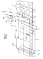
- a cladding material 1 In the upstream zone of the line, one sinks on a cladding material 1 a binder composition 2, and usually covered by means of a second facing material 3.
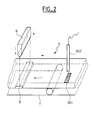
- the passage of the assembly under the forming plate 4 gives a preform 5, which moves, supported by a conveyor belt 7, towards the downstream zone of the line, where it is cut transversely by a cutting device 9, constituted usually by a roller equipped with a knife (figure 2), to give plates.
- upstream and downstream refer to the meaning of scrolling of the preform 5.
- upstream zone we mean in the present the part of the production line located at near the forming plate 4.
- Downstream zone means the part of the line of production located near the cutting device 9.
- the hydraulic binder composition comprises preferably plaster.
- Facing materials 1 and 3 can be consisting of sheets of paper or cardboard, mats of glass or any material known to those skilled in the art as being able to be used as facing material.
- marking means 300 are provided, generally upstream of the forming plate 4, to produce at least one brand, preferably on the facing material 3 of the preform 5.
- the brand is therefore generally carried out upstream of the forming plate 4, that is to say before the preform 5 is formed.
- the mark may be produced by depositing a material such as an ink on the surface of the facing material, to make a stain, a line, or a sign any.
- the deposited material may or may not be visible the null eye.
- the dimensions of the brand can be very variables.
- the mark may also be constituted by a relief or hollow formed on the surface of the material of facing.
- the marking means 300 can therefore be consisting of an ink-stamp part which is regularly moving back and forth in direction of facing material 3 illustrated by the double arrow B. When the buffer piece comes into contact with the facing material 3, it leaves a mark 301 on the face this material.
- marking 300 such as an encoder wheel coupled to a ink jet device for triggering a net anchoring (indexing of jet speed, depending on the cardboard speed) at the periodicity wanted, mastered by the man of the metier or the operator.
- These detection means 302 are of course chosen depending on the type of the mark to be detected. They can be constituted by a photoelectric sensor.
- a detection signal is sent to actuating means (not shown), which send then an actuating signal to the cutting device 9, so that the latter cuts the preform 5 for give a plate.
- additional detection 303 are provided downstream of marking means 300, preferably in the upstream zone, generally upstream of the forming plate 4.
- These additional detection means 303 are generally of the same type as the detection means 302, since they must be able to detect the mark 301.
- Additional means of actuation are then also provided for, after receiving a signal from detection from these additional means of detection 303, send an actuation signal to a apparatus for making an impression or reservation in the preform 5.
- FIG. 1 The preferred apparatus for performing fingerprints is shown schematically in FIG. 1
- first two pulleys 102 and 103 On this frame 101 are supported, at a first end 104, first two pulleys 102 and 103 and, at a second end 107, two second pulleys 105 and 106.
- the first pulleys 102,103 are in a foreground, the second 105,106 pulleys in a second plane and the foreground is parallel to the background.
- the pulley 102 and the pulley 105 are located one in facing each other and identical.
- the pulley 103 and the pulley 106 are also located opposite each other and identical.
- the pulleys 102, 103, 105 and 106 can turn on themselves.
- a first transmission belt 108 surrounds the first pulleys 102,103 and a second belt of transmission 109 surrounds the second pulleys 105,106.
- the transmission belts 108 and 109 are identical. They are connected to each other by least one thread 111.
- This wire 111 is fixed in a removable manner to the first and second straps 108,109 and it extends between these 108,109 belts so that its longitudinal axis is parallel to the axis of rotation of the pulleys.
- the pulley 102 when one of the pulleys, for example the pulley 102, turns, it drives the belt of transmission 108 which itself drives the other pulley located in the same plane as it (the pulley 103) as well than the elongated form means 110.
- the latter moves then according to the trajectory defined, on the one hand, by the loop constituted by the belt 108 and, secondly, as it is connected to the second belt 109, also by the loop constituted by the latter.
- the symmetry of the apparatus according to the invention allows therefore at the axis of the wire 111 to move according to an ellipse, its axis remaining constantly parallel to that of pulleys.
- the apparatus may also include means for rotating at least one of the pulleys. These means can possibly lead to two pulleys by means of the tree on which they are mounted.
- the wire 111 generally has a shape cylindrical but it can take a large number of forms of which we may mention the forms parallelepidea, prismatic, etc.
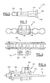
- wires 111 are arranged parallel to one another to others, along the transmission belts 108 and 109 (see Figure 3).
- the pulleys are preferably gear wheels and the transmission belts of the chains being able cooperate with these gears.
- the support member 113 is visible in FIGS. and 7.
- It comprises the bore 118 able to cooperate with the corresponding part 117 of the pin-thread axis 114 and a bore 121 opening into the bore 118.
- This bore 121 is threaded so that one can screw a pressure screw 122 for compressing the wire 111 present inside the bore 118 for the purpose of hold firmly (see Figure 4).
- the assembly of FIG. simply introduce the part 117 of the pin-wire axis 114 in the support piece 113, to remove the bearing pin from normal roll of the link 112, to introduce into the axis of the roll part 116 of the pin-thread pin 114, to tighten the whole by aiming a nut 123 on the end 115 of the wire gripper axis 114, to introduce the wire 111 into the central bore 120 of the yoke pin 114 and y hold firmly by screwing the set screw 122 in the threaded bore 121 until it compresses effectively the thread 111.
- pin-thread axis 114 is mounted such that so that his head 119 is on the inside of the chain, that is to say turned towards the other chain.
- the support member 113 preferably comprises two pairs (bore 118, threaded bore 121), spacing between the axes of the holes 118 corresponding to the normal spacing between the axes of the rollers of a chain link 112, so that two wires 111 can be maintained on the same link 112, as can be deduced from Figures 6 and 7.
- the distance between the belts of this transmission apparatus is at least equal to the width of the preform 5.
- these belts and pulleys are located each longitudinal side of the preform.
- the device is arranged in a appropriate for that when his belts transmission turn, its elongated medium creates a impression in the preform 5.
- the apparatus may be above the preform 5, in this case, he creates the impression 12 or under the preform 5, in which case it creates the imprint 12bis visible on the figure 10.
- the apparatus according to the invention is located above the preform 5.
- the engine operation is set to what the belts are moving at the same speed as the preform.
- the imprint position 12 is not directly related to that of a mark 301, so that a footprint 12 may or may not be performed on a mark 301.
- the position of the imprint 12bis is not directly linked to that of a mark 301, so 12bis may or may not be carried out under a mark 301.
- the position of the mark 301 and the mark are advantageously chosen so that the preform 5 is cut at an impression 12.
- the cutting device can be set to cut the preform away from the place where this impression 12a was carried out (that is to say on the other side of the preform).
- the preform is preferably cut approximately middle of the footprint 12 or 12bis.
- the means additional actuation are suitable, after receiving a detection signal from the additional means of detection 303, to send a actuation signal to an input device slats under the preform 5.
- the additional means of detection 303 and the electronic means therefore make it possible to introduce the latte 6 under the preform 5, after the detection of the mark 301, by sending an actuation signal to a slats introduction device 6 under the preform 5.
- the position of the mark 301 is not directly linked to the introduction of batten 6, so that latte 6 may or may not be introduced just under a brand 301.
- edges in this presentation we mean the edges perpendicular to the direction of travel of the carpet carrier in a plate production line at hydraulic binder base. Such transverse edges are also called “slabs of plaque”.
- a slat 6 is inserted between the preform 5 and the beginning of conveyor belt 7.
- the distance between the forming plate 4 and the beginning of conveyor belt 7 is such that preform 5 has not yet had the time to harden substantially and still presents a great plasticity.
- the introduction is done in such a way that the longitudinal axis of the slat 6 is substantially perpendicular to the direction of travel of the carpet carrier 7.
- the batten 6 is then driven by the carpet carrier 7, just like the preform 5.
- the grip hydraulic and hardening of the composition of plaster 2 is then carried out throughout the journey of the preform 5, designated by the arrows A.
- the withdrawal of the slat 6 takes place before the section of the preform 5.
- the withdrawal of the slat 6 can be carried out according to any appropriate way.
- the slat 6 protrudes from the preform 5, and can be removed quickly according to a direction substantially perpendicular to the direction moving the conveyor belt 7 and moving away of the last. This withdrawal action is illustrated by arrow B in FIG.
- the removal of the slat 6 can also occur by the fall of this slat 6 in the space between two constituent rollers of conveyor belt system which, in general, is not continuous throughout the production line but is formed by several mats driven by rollers between which there are free spaces.
- the preform 5 continues to move, always driven by the carpet carrier 7 and the hardening of the composition of plaster 2 continues.
- the mark 301 is then detected, in the downstream zone of the production line, by the means additional detection 302 that then trigger the operation of the cutting device 9.
- the position of mark 301 and that of thinning 8 are advantageously chosen so that the preform 5 is cut at the level of the thinning 8, preferably about the middle of this thinning.
- plates 9bis having edges are obtained transverse thinned 10 visible in FIG. the lengths are defined by the distance traveled by the conveyor belt between two cutting operations, that is, in general by the distance traveled by the conveyor belt between two consecutive thinning 8. This plate 9bis therefore has two edges transverse thinned 10.
- each thinning 8 depends on the dimensions of the batten 6.
- the latter is usually a parallelepiped whose thickness is generally between 0.5 and 4 mm, preferably between 1.5 and 4 mm. Its width is generally between 5 and 20 cm and its length is at least about equal to the width of the preform 5 (possibly diminished by the width of the longitudinal strips "tape" present if necessary), but in general superior in order to be able to seize it for remove it from under the preform 5.
- the batten 6 is of greater length to the width of the preform 5, so as to protrude compared to this one, which can facilitate its withdrawal.
- the constituent material of the slats 6 is of little importance, moment that it allows these slats to withstand the weight of the thickness of preform 5 which is above each slat 6. So it can be a plastic material, wood, metal, etc. with good resistance to wear and stability over time.
- the process which has just been described comes in addition to a known method of manufacturing plasterboard having two longitudinal edges thinned.
- the latter generally provides for the establishment of a tape, usually plastic, called generally "tap", on each longitudinal side of the conveyor belt 7.
- Tap a tape, usually plastic
- the length of gypsum board manufactured depends of course the speed of movement of the carpet carrier and the frequency of cutting operations.
- the frequency of cutting operations is generally directly related to the frequency of introduction of slats, because one generally seeks to obtain plates having two transverse edges thinned, and the frequency slats introduction depends on the detection marks 301 and therefore the frequency of the operations of marking.
- the method according to the invention includes both making an imprint 12 or 12bis in the preform 5 and the introduction of a batten 6 under the preform 5.
- the additional means of actuation are therefore suitable after detection of a mark 301 by the means additional detection 303, to send a signal actuating means for producing the impression 12 or 12bis as well as an actuation signal at slats introduction device 6, in view to introduce a slat 6 under the preform, to leave the hydraulic take place then remove the slat 6, as explained previously.
- the steps of introducing a slat 6 under the preform 5 and then hydraulic catch of the hydraulic binder composition and removal of the latte 6 take place after the completion step of the impression in the preform 5.
- impression 12a is preferably made either at the opposite of where it is intended to introduce the latte 6 (impression 12), where it is intended to introduce this slat 6 (imprint 12a).
- the production line of binder-based plates hydraulic system according to the invention is preferably a line production of plates based on hydraulic binder to aminicis edges.
- Such a line may comprise a device introduction of laths and / or means for fingerprinting.
- a production line of binder-based plates hydraulics with aminicis edges provided with means or a device for the introduction of slats 23 under the preform 5 will first be described in detail in referring to Figures 1, 2 and 8 to 15.
- This device comprises a slat shop 20 formed of a horizontal rectangular surface 21 from the corners of which rise vertically and parallel, four angular pieces 22, in the form of angles and turned towards each other, so as to frame a stack of slats 23.
- this slatted store 20 is such it can store a high number of slats 23 (see also Figures 12 and 13).
- the horizontal surface 21 of the slat magazine 20 is supported by feet 24.
- first slat 23 At the level of the first slat 23, that is to say located at the bottom of the pile, are arranged parallel two cylinders 26, which are oriented in order to extract the first slat 23 from the stack in the pushing and sliding it towards an inclined plane 27 consisting of an inclined surface 28 down and a flange 29 at the bottom to hold the latte which has just been extracted and guide it later.
- a cylinder 31 is arranged parallel to the longitudinal axis inclined plane 27, so that the actuation of this cylinder 31 can give an impetus to the latte which has just been extracted from the latte magazine 20.
- La latte so propelled can then move by sliding parallel to the longitudinal axis of the inclined plane 27, whose rim 29 guides it towards a second inclined plane 32 which extends the first inclined plane 27, on the transverse opposite the side 30.
- This second inclined plane 32 also consists of an inclined surface 33 provided a rim 34 at its lower part. It includes in in addition to a stop 35 at its end opposite to the jack 31, this stop being generally constituted of a pneumatic damper and being intended to put a term to the displacement of the slat propelled by the jack 31.
- the flange 34 is provided with openings 36 opposite of which are arranged two cylinders 37 oriented to propel the lath positioned on the second inclined plane 32 upwards of inclined surface 33.
- the first inclined plane 27 and the second plane inclined 32 are supported by feet, respectively, 38 and 39.
- flat surface 40 is provided parallel to the surface 23, between the latter and the first inclined plane 27 to support horizontally a slat extracted from the slatted shop 20 before its descent on the surface inclined 28 of the first inclined plane 27.
- the foot height 24, 35 and 36 is chosen so a slat positioned on the second inclined plane 32 is at a lower height than the preform 5.
- the length of the second inclined plane 32 is at least equal to that of slat 23, that is to say at least equal to, and preferably greater than, the width of the preform 5.
- the difference between the length of the slat and the width of the preform 5 makes it possible to grasp the lath and remove once the gypsum composition hardened.
- the production line according to the invention comprises usually electronic means that control his functioning and allow, where appropriate, to enslave between them the implementations of different operations.
- electronic means are able to send an actuation signal to the slats introduction device 23, after the receiving a detection signal from the means additional detection 303.
- the frequency of the introduction of slats under the preform is determined by the frequency of making marks 301 on the facing material 3 of the preform 5.
- Figure 16 represents the upstream zone of such line comprising a variant of the apparatus for the fingerprinting, which is seen in profile on this figure.
- the apparatus comprises four first gears 201,202,203,204 supported by a built 205 and surrounded by a chain 206 constituted by links, some of which, the links 207, support each 2-wire, as indicated in connection with the figure 2.
- This device is symmetrical with respect to a plane vertical aligned with the direction of travel of the preform 5.
- the threads held by the links 207 extend transversely with respect to the preform 5 to a second chain, identical to the chain 206, and which surrounds second gear wheels identical to first gears 201,202,203,204.
- the appliance is equipped with an electric motor 209 driving in rotation by means of a belt 211 the shaft 210 on which are mounted the wheel 203 and its symmetrical wheel.
- the rotation of these wheels causes of the chain 206 in the direction indicated by the arrow D.
- This preform 5 is obtained in a known manner by introduction of the hydraulic binder paste according to the arrow E between the first cladding material 2 and the second facing material 3 and passage of the whole between the upper plateaux 214 and lower 215 of forming the apparatus.
- the distance between the gears 201,202,203,204 and their symmetrical wheels is at least equal to that of the preform 5 so that these gears do not touch not this preform 5.
- the apparatus according to the invention is fixed at a height appropriate for the operation of the line of production, the displacement of the chain 206 resulting that of the son connected to the link 207, these son pass in the forming plate, that is to say between the trays 214 and 215 and protrude downward from the top plate 214.
- the space occupied by these wires between the upper plate 114 and the second material of siding 3 is then reflected at this location by a thinning of the thickness of the preform 5.
- the electronic means of the production line are able to send a signal to this device, so that it performs every imprint after receiving a detection signal from the additional detection means 303.
- the means for carrying out fingerprints cooperate with the introductory device slats under the preform 5 (constituted by the means 20 to 22 and 24 to 39 described above in relation to the Figures 11 to 15).
- the additional means of actuation are therefore suitable after detection of a mark 301 by the means additional detection 303, to send a signal actuating means for producing the impression 12 or 12bis as well as an actuation signal at slat introduction device 6.
- This variant is then advantageously arranged in upstream of the slats introduction device.
- the electronic means then calculate preferably the precise moment at which they must send the actuating signals to the apparatus of realization fingerprints and slats introduction device, in order to synchronize their operations, so that the lath is introduced into a footprint 12bis located on the underside of the preform 5, or if the impression 12 is on the upper side of the preform 5, substantially the opposite of this footprint 12.
- the introduction of slats 23 under the preform 5 is operated in part by the apparatus for the realization prints.
- this mechanical link between the apparatus of fingerprinting and the introduction device slats can be replaced by a combination device grouping together means of realization imprint and latte introduction means.
- the chain 206 is then provided with a thrust finger 216 which is fixed on the outer side of the chain 206, that is to say the one opposite to the one where the threads are.
- This pushing pin 216 has the function of striking and move the pusher 217 during the rotation of the chain 206. It can be attached to a link in the chain 206 for example in place of a roller bearing shaft of this link.
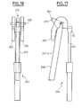
- a pusher 217 The shape of a pusher 217 is more visible on the Figures 17 and 18.
- This pusher includes a portion elongated ruler 218 provided at one end of a triangular shaped part rectangle 219 crossing by an axis 220 which protrudes on both sides of the part 219.
- the top of the rectangle triange is cut to give a face 221 parallel to the axis of the shaped portion Rule 218.
- the pusher 217 can occupy two positions. In his position initial (shown in dotted lines), it is based on the plateau 215 and is turned towards the ground, so that its axis 220 is disposed transversely to the preform 5 and his face 221 is at the party bottom of the inclined surface 33, in the opening 36 from the edge 34.
- the thrust finger 216 on the chain 206 is located at a distance, compared to the wires held by the links 207, such that the slat 23 is introduced substantially opposite the location of the preform 5 where said threads have formed the impression. This has for consequence that material displacement caused by the introduction of the slat 23 is at least partially offset by the footprint. It follows that the preform present no hump at the opposite spot to where the latte 23 was introduced. This means that after withdrawal of this slat 23, the thinning obtained on the bottom of the preform 5 does not match any bump on the top of the preform 5.
- the pusher 217 moved by the thrust finger 216 comes in a second position by finishing his race in a receptacle, visible in Figures 17 and 18, and which is formed by two arched pieces 222 fixed by their upper extremities on both sides of the outer end 225 of the rod 223 of a jack 224.
- Each side of the axis 220 of the pusher 217 is received in an arcuate part 222 and the parts 219 and 218 of the pusher 217 can be inserted into the space formed between the arcuate pieces 222, under the rod 223 of the jack 224.
- the rod 223 of the jack 224 is output, to receive the pusher 217.
- the dimensions of the pusher 217 are chosen so that it stays above the inclined surface 33.
- the jack 224 can be fixed to the frame 205 of the device, its location and its dimensions being determined according to the pusher 217 with which it must cooperate.
- the cylinder 224 therefore has the function of return the pusher 217 to its initial position. Its stem 223 is normally in the extended position, waiting for receive the pusher 217.
- each of the chains being provided with a pushing finger 216 cooperating each with a jack 224, and this, in a synchronized way.
- Electronic and pneumatic means (or possibly hydraulic) of the production line control the operation of the production apparatus footprints and slats introduction device under the preform (constituted by means 20 to 22 and 24 to 39 described above), so that once the pusher 117 returned to its initial position and the rod 223 of the cylinder 224 again out, a new slat 23 can be slipped on the inclined plane 33.
- the actuation of the cylinder 224 is determined by detection for example by means of of a photoelectric sensor, the passage of a pin or finger attached to a suitable place on the chain 206, by example in the same way as the push finger 216, this ergot playing the role of flag, that is to say that when detected by the photoelectric sensor arranged at a suitable place on the production line or the apparatus, the electronic means control the return of the rod 223 of the cylinder 224 in the body of the cylinder, this return entailing, as explained above, the return of the pusher 217 to its initial position. of the limit sensors of cylinder 224, can then, once the rod 223 returned, cause a new actuation of the jack 224 to pull out its rod 223, which drops the pusher 217 to its original position.
- the frame 205 of the device may, as is apparent of Figure 16, be integral with the trays 214 and 215. It follows that the device can be used instead a flat forming or a master roll that we use classically.
Landscapes
- Engineering & Computer Science (AREA)
- Chemical & Material Sciences (AREA)
- Ceramic Engineering (AREA)
- Mechanical Engineering (AREA)
- Structural Engineering (AREA)
- Processing And Handling Of Plastics And Other Materials For Molding In General (AREA)
Abstract
Description
- la figure 1 représente schématiquement et en perspective, la partie amont d'une ligne de production de plaques à base de liant hydraulique selon l'invention ;
- la figure 2 représente schématiquement et en perspective, la partie aval d'une ligne de production de plaques à base de liant hydraulique selon l'invention ;
- la figure 3 représente schématiquement et en perspective, un appareil pour la réalisation d'empreintes dans la préforme à base de liant hydraulique ;
- la figure 4 représente schématiquement et en coupe l'assemblage d'un fil sur un maillon de chaíne ;
- la figure 5 représente schématiquement un axe pince-fil ;
- la figure 6 représente schématiquement et en vue de dessus une pièce-support montée sur un maillon de chaíne ;
- la figure 7 représente schématiquement la pièce-support de la figure 6 en vue de face ;
- la figure 8 représente une plaque que l'on peut obtenir avec le procédé selon l'invention ;
- la figure 9 représente une autre plaque que l'on peut obtenir avec le procédé selon l'invention ;
- la figure 10 illustre une étape intermédiaire optionnelle d'un procédé de fabrication de plaques à base de liant hydraulique ;
- la figure 11 représente schématiquement et en perspective, un dispositif pour l'introduction de lattes sous une préforme à base de liant hydraulique ;
- la figure 12 représente schématiquement et en vue de dessus, le dispositif de la figure 11 ;
- la figure 13 représente schématiquement et en vue de côté, le dispositif de la figure 11 ;
- la figure 14 représente schématiquement et en vue de côté une variante du dispositif de la figure 11 ;
- la figure 15 représente schématiquement et en coupe, un détail du dispositif de la figure 11 illustrant l'introduction d'une latte sous une préforme à base de liant hydraulique ;
- la figure 16 représente schématiquement une partie d'une ligne de production de plaques à base de liant hydraulique selon l'invention comportant une variante l'appareil pour la réalisation des empreintes; et
- les figures 17 et 18 représentent schématiquement un poussoir et son réceptacle, éléments de l'appareil pour la réalisation des empreintes de la figure 16.
- une extrémité filetée 115,
- une partie généralement cylindrique et lisse 116, apte à s'introduire dans le rouleau du maillon de chaíne 112 en vue de remplacer l'axe porte-rouleau utilisé classiquement,
- une partie lisse également généralement cylindrique et lisse 117, de diamètre généralement supérieur à celui de la partie 116 et apte à s'introduire dans le perçage 118 de la pièce support 113 (voir figures 6 et 7),
- une tête 119, et
- un alésage central 120 usiné généralement à partir de la tête 119, pouvant s'étendre jusqu'à la partie 116 et destiné à recevoir le fil 111.
- l'axe longitudinal du rebord 34 du deuxième plan incliné 32 est perpendiculaire à l'axe longitudinal du tapis transporteur ;
- les moyens 32,33,34,35 pour supporter la latte déplacée se situent en face du début du tapis transporteur 7 ; et
- la surface inclinée 33 du deuxième plan incliné 32 est adjacente au tapis transporteur 7.
Claims (19)
- Procédé de fabrication de plaques à base de liant hydraulique à partir d'une préforme (5) destinée à être coupée, comprenant les étapes de :1) réalisation d'au moins une marque (301) sur un matériau de parement (2 ou 3) de la préforme (5) ;2) détection de la marque (301) ; et3) envoi d'un signal d'actionnement à un dispositif de coupe (9) de la préforme(5).
- Procédé selon la revendication 1, caractérisé en ce que dans l'étape 1) la marque (301) est réalisée au moyen d'une pièce formant tampon encreur.
- Procédé selon la revendication 1 ou la revendication 2, caractérisé en ce que, dans l'étape 2), la marque (301) est détectée au moyen d'un capteur photoélectrique.
- Procédé selon l'une des revendications 1 à 3, caractérisé en ce que la marque (301) est réalisée avant la formation de la préforme 5.
- Procédé de fabrication de plaques à base de liant hydraulique selon l'une des revendications 1 à 4, comprenant en outre, avant l'étape 2), une étape supplémentaire de détection de la marque (301), puis une étape de réalisation d'une empreinte (12 ou 12bis) dans la préforme (5).
- Procédé de fabrication de plaques à base de liant hydraulique selon l'une des revendications 1 à 4, comprenant en outre, avant l'étape 2), une étape supplémentaire de détection de la marque (301), suivie d'une étape d'introduction d'une latte (6,23) sous la préforme (5), d'une étape où on laisse la prise hydraulique de la composition de liant hydraulique s'effectuer et d'une étape de retrait de la latte (6,23).
- Procédé de fabrication de plaques à base de liant hydraulique selon la revendication 5, comprenant en outre, après l'étape supplémentaire de détection de la marque (301), une étape d'introduction d'une latte (6,23) sous la préforme (5), suivie d'une étape où on laisse la prise hydraulique de la composition de liant hydraulique s'effectuer et d'une étape de retrait de la latte (6,23).
- Procédé selon la revendication 7, caractérisé en ce que les étapes d'introduction d'une latte (6,23) sous la préforme (5), puis de prise hydraulique de la composition de liant hydraulique et de retrait de la latte (6,23), ont lieu après l'étape de réalisation de l'empreinte (12 ou 12bis).
- Procédé selon la revendication 8, caractérisé en ce que l'introduction de chaque latte (6,23) est effectuée à l'endroit où l'empreinte (12bis) a été réalisée ou à l'opposé de l'endroit où a été réalisée l'empreinte (12).
- Procédé selon l'une des revendications 1 à 9, caractérisé en ce que le liant hydraulique comprend du plâtre.
- Ligne de production de plaques à base de liant hydraulique, comprenant :a) dans une zone amont de la ligne de production, des moyens de marquage (300) d'un matériau de parement (2 ou 3) de la préforme (5) ;b) dans une zone aval de la ligne de production, des moyens de détection (302) d'une marque (301) réalisée par les moyens de marquage (300);c) un dispositif de coupe (9) ; etd) des moyens d'actionnement, pour actionner ledit dispositif de coupe (9), après réception d'un signal de détection provenant des moyens de détection (302).
- Ligne de production de plaques à base de liant hydraulique selon la revendication 11, caractérisée en ce que les moyens de marquage comprennent une pièce formant tampon encreur.
- Ligne de production de plaques à base de liant hydraulique selon la revendication 11 ou la revendication 12, caractérisée en ce que les moyens de détection comprennent un capteur photoélectrique.
- Ligne de production de plaques à base de liant hydraulique selon l'une des revendications 11 à 13, caractérisée en ce qu'elle comprend en outre :des moyens supplémentaires de détection (303) de la marque (301) ;des moyens de réalisation (101-123, 201-224) d'une empreinte (12 ou 12bis) dans la préforme (5) ;des moyens supplémentaires d'actionnement, pour actionner lesdits moyens (101-123, 201-224) de réalisation d'une empreinte (12 ou 12bis) dans la préforme (5), après réception d'un signal de détection provenant des moyens supplémentaires de détection (303).
- Ligne de production de plaques à base de liant hydraulique selon l'une des revendications 11 à 13, caractérisée en ce qu'elle comprend en outre :des moyens supplémentaires de détection (303) de la marque (301) ;des moyens (20-22, 24-39) d'introduction de lattes (6,23) sous la préforme (5) ;des moyens supplémentaires d'actionnement, pour actionner lesdits moyens (20-22, 24-39) d'introduction de lattes (6,23) sous la préforme (5), après réception d'un signal de détection provenant des moyens supplémentaires de détection (303).
- Ligne de production de plaques à base de liant hydraulique selon l'une des revendications 11 à 13, caractérisé en ce qu'elle comprend en outre :des moyens supplémentaires de détection (303) de la marque (301) ;des moyens de réalisation (101-123, 201-224) d'une empreinte (12 ou 12bis) dans la préforme (5) ;des moyens (20-22, 24-39) d'introduction de lattes (6,23) sous la préforme (5) ;des moyens supplémentaires d'actionnement, pour actionner, après réception d'un signal de détection provenant des moyens supplémentaires de détection (303), lesdits moyens de réalisation d'une empreinte (12 ou 12bis) dans la préforme (5) ainsi que lesdits moyens (20-22, 24-39) d'introduction de lattes (6,23) sous la préforme (5).
- Ligne de production de plaques à base de liant hydraulique selon la revendication 16, caractérisé en ce que les moyens supplémentaires d'actionnement prévoient que l'introduction de chaque latte (6,23) soit effectuée sensiblement à l'endroit où l'empreinte (12bis) a été réalisée ou à l'opposé de l'endroit où a été réalisée l'empreinte (12).
- Ligne de production de plaques à base de liant hydraulique selon la revendication 14, 16 ou 17, caractérisé en ce que les moyens de réalisation (101-123) d'une empreinte (12 ou 12bis) sont constitués par un appareil (101-123) comprenant au moins :un bâti (101) ;deux premières poulies (102,103) supportées à une première extrémité (104) du bâti (101) et deux secondes poulies (105,106) à une seconde extrémité (107) du bâti (101); les premières poulies (102,103) et secondes poulies (105,106) étant dans des plans parallèles ; les poulies en regard l'une (102,103) de l'autre (105,106) étant identiques ;deux courroies de transmission (108,109) entourant respectivement les premières poulies (102,103) et les secondes poulies (105,106);au moins un fil (111) fixé de façon amovible aux courroies (108,109) et s'étendant entre ces courroies (108,109), de telle sorte que son axe longitudinal soit parallèle à l'axe de rotation des poulies (102,103,105,106).
- Ligne de production de plaques à base de liant hydraulique selon l'une des revendications 11 à 18, caractérisée en ce que le liant hydraulique comprend du plâtre.
Priority Applications (33)
| Application Number | Priority Date | Filing Date | Title |
|---|---|---|---|
| DK02291132.5T DK1361030T3 (en) | 2002-05-06 | 2002-05-06 | Process for producing sheets based on hydraulic binder and production line for producing such sheets |
| ES02291132.5T ES2659388T3 (es) | 2002-05-06 | 2002-05-06 | Procedimiento de fabricación de placas a base de aglomerante hidráulico y instalación de producción de tales placas |
| EP02291132.5A EP1361030B1 (fr) | 2002-05-06 | 2002-05-06 | Procédé de fabrication de plaques à base de liant hydraulique ainsi qu'une ligne de production de telles plaques |
| NZ552217A NZ552217A (en) | 2002-02-26 | 2003-02-25 | Method of manufacturing sheets based on hydraulic binder, production line for producing such sheets and apparatus for making an impression |
| US10/505,543 US7790090B2 (en) | 2002-02-26 | 2003-02-25 | Method of manufacturing sheets based on hydraulic binder, production line for producing such sheets and apparatus for making an impression |
| ARP030100612 AR038609A1 (es) | 2002-02-26 | 2003-02-25 | Procedimiento de fabricacion de placas a base de aglomerante hidraulico, instalacion de produccion de tales placas y aparato para la realizacion de una huella |
| EP03732623.8A EP1480800B1 (fr) | 2002-02-26 | 2003-02-25 | Procede de fabrication de plaques a base de liant hydraulique, ligne de production de telles plaques et appareil pour la realisation d'une empreinte |
| KR1020097014966A KR100960605B1 (ko) | 2002-02-26 | 2003-02-25 | 수경성 결합제 기반의 시트의 제조방법, 상기 시트를 생산하기 위한 생산라인 및 압흔 제조장치 |
| CNB038046571A CN100411839C (zh) | 2002-02-26 | 2003-02-25 | 制造基于水凝粘合剂的板材的方法、用于生产该板材的生产线以及用于制造印痕的装置 |
| DK03732623.8T DK1480800T3 (en) | 2002-02-26 | 2003-02-25 | PROCEDURE FOR MANUFACTURING PLATES BASED ON HYDRAULIC BINDING MATERIAL, MANUFACTURING LINE FOR SUCH PLATES AND APPARATUS FOR PERFORMING A PRINT |
| PL370532A PL202026B1 (pl) | 2002-02-26 | 2003-02-25 | Sposób wytwarzania płyt na bazie spoiwa hydraulicznego, linia produkcyjna do wytwarzania takich płyt i urządzenie w szczególności do wykonania odcisku oraz zastosowanie takiego urządzenia w linii produkcyjnej |
| ES03732623.8T ES2549680T3 (es) | 2002-02-26 | 2003-02-25 | Procedimiento de fabricación de placas a base de aglomerante hidráulico, instalación de producción de tales placas y aparato para la realización de una huella |
| NZ534531A NZ534531A (en) | 2002-02-26 | 2003-02-25 | Method of manufacturing sheets based on hydraulic binder, production line for producing such sheets and apparatus for making an impression |
| DK04027078.7T DK1510316T3 (en) | 2002-02-26 | 2003-02-25 | PROCEDURE FOR MANUFACTURING PLATES BASED ON HYDRAULIC BINDING MATERIAL, PRODUCTION LINE FOR MANUFACTURING SUCH PLATES AND APPARATUS FOR PRINTING |
| MXPA04008186A MXPA04008186A (es) | 2002-02-26 | 2003-02-25 | Procedimiento de fabricacion de placas a base de aglomerante hidraulico, instalacion de produccion de tales placas y aparato para la realizacion de una huella. |
| AU2003239650A AU2003239650B2 (en) | 2002-02-26 | 2003-02-25 | Method for production of sheets made from binder, production line for said sheets and device for generation of an impression |
| EP04027078.7A EP1510316B1 (fr) | 2002-02-26 | 2003-02-25 | Procédé de fabrication de plaques à base de liant hydraulique, ligne de production de telles plaques et appareil pour la réalisation d'une empreinte |
| IL16351703A IL163517A0 (en) | 2002-02-26 | 2003-02-25 | Method for manufacturing sheets based on hydraulicbinder, productionline for producing such sheets and apparatus for making an impression |
| PCT/FR2003/000606 WO2003072326A2 (fr) | 2002-02-26 | 2003-02-25 | Procédé de fabrication de plaques a base de liant hydraulique, ligne de production de telles plaques et appareil pour la réalisation d'une empreinte |
| BRPI0308074A BRPI0308074B1 (pt) | 2002-02-26 | 2003-02-25 | método de fabricação de chapas à base de aglutinante hidráulico, linha de produção para produzir chapas a base de aglutinante hidráulico, aparelho para fazer uma impressão e uso do aparelho para fazer uma impressão |
| RU2004128450A RU2313452C2 (ru) | 2002-02-26 | 2003-02-25 | Способ изготовления плит на основе гидравлического связующего, технологическая линия по производству таких плит и устройство для реализации отпечатков |
| ES04027078.7T ES2618522T3 (es) | 2002-02-26 | 2003-02-25 | Procedimiento de fabricación de placas a base de aglomerante hidráulico, instalación de producción de tales placas y aparato para la realización de una huella |
| KR10-2004-7013355A KR20040093071A (ko) | 2002-02-26 | 2003-02-25 | 수경성 결합제 기반의 시트의 제조방법, 상기 시트를생산하기 위한 생산라인 및 압흔 제조장치 |
| JP2003571058A JP2005525243A (ja) | 2002-02-26 | 2003-02-25 | バインダからシートを製造する方法、該シートの製造ラインおよび圧痕を生成するための装置 |
| CA2476497A CA2476497C (fr) | 2002-02-26 | 2003-02-25 | Procede de fabrication de plaques a base de liant hydraulique, ligne de production de telles plaques et appareil pour la realisation d'une empreinte |
| ZA2004/06341A ZA200406341B (en) | 2002-02-26 | 2004-08-11 | Method of manufacturing sheets based on hydraulic binder production line for producing such sheets and apparatus for making an impression |
| IL179895A IL179895A0 (en) | 2002-02-26 | 2004-08-12 | Method for manufacturing sheets based on hydraulic binder, production line for producing such sheets and apparatus for making an impression |
| IL163517A IL163517A (en) | 2002-02-26 | 2004-08-12 | Method of production and production line for sheets based on hydraulic coupling material and device for stamping |
| CO04084752A CO5601040A2 (es) | 2002-02-26 | 2004-08-30 | Procedimiento de fabricacion de placas a base de aglomerante hidraulico, instalacionde produccion de tales placas y aparato para la realizacion de una huella |
| NO20044058A NO20044058L (no) | 2002-02-26 | 2004-09-24 | Fremgangsmate for fremstilling av plater av vaeskeformet bindemiddel, produksjonslinje for platene og anordning for dannelse av inntrykk |
| US10/904,738 US7651327B2 (en) | 2002-02-26 | 2004-11-24 | Production line for producing sheets based on hydraulic binder and method of manufacturing the same |
| IL179895A IL179895A (en) | 2002-02-26 | 2006-12-06 | Method for manufacturing sheets based on hydraulic binder, production line for producing such sheets and apparatus for making an impression |
| JP2009042475A JP2009113497A (ja) | 2002-02-26 | 2009-02-25 | バインダからシートを製造する方法、該シートの製造ラインおよび圧痕を生成するための装置 |
Applications Claiming Priority (1)
| Application Number | Priority Date | Filing Date | Title |
|---|---|---|---|
| EP02291132.5A EP1361030B1 (fr) | 2002-05-06 | 2002-05-06 | Procédé de fabrication de plaques à base de liant hydraulique ainsi qu'une ligne de production de telles plaques |
Publications (2)
| Publication Number | Publication Date |
|---|---|
| EP1361030A1 true EP1361030A1 (fr) | 2003-11-12 |
| EP1361030B1 EP1361030B1 (fr) | 2017-11-15 |
Family
ID=29225739
Family Applications (1)
| Application Number | Title | Priority Date | Filing Date |
|---|---|---|---|
| EP02291132.5A Expired - Lifetime EP1361030B1 (fr) | 2002-02-26 | 2002-05-06 | Procédé de fabrication de plaques à base de liant hydraulique ainsi qu'une ligne de production de telles plaques |
Country Status (3)
| Country | Link |
|---|---|
| EP (1) | EP1361030B1 (fr) |
| DK (1) | DK1361030T3 (fr) |
| ES (1) | ES2659388T3 (fr) |
Cited By (4)
| Publication number | Priority date | Publication date | Assignee | Title |
|---|---|---|---|---|
| US7431783B2 (en) | 2002-04-10 | 2008-10-07 | Lafarge Platres | Method and apparatus for production of plaster plates having 4 tapered edges |
| US7651327B2 (en) | 2002-02-26 | 2010-01-26 | Lafarge Platres | Production line for producing sheets based on hydraulic binder and method of manufacturing the same |
| US8257525B2 (en) | 2003-08-25 | 2012-09-04 | Lafarge Platres | Production method for hydraulic binder-based, tapered-edge boards |
| CN107336340A (zh) * | 2017-06-30 | 2017-11-10 | 浙江开元新型墙体材料有限公司 | 蒸压加气板材的印签修裁复合机构 |
Citations (3)
| Publication number | Priority date | Publication date | Assignee | Title |
|---|---|---|---|---|
| DE872025C (de) * | 1950-12-05 | 1953-03-30 | Christian Rieckhof | Verfahren zum Herstellen von Ausnehmungen an Deckenhohlsteinen |
| GB2221181A (en) * | 1988-02-13 | 1990-01-31 | Poly Machinery Limited | Bag manufacture |
| US5842280A (en) * | 1996-02-14 | 1998-12-01 | Robell; Glenn | Gridded measurement system for construction materials |
-
2002
- 2002-05-06 DK DK02291132.5T patent/DK1361030T3/en active
- 2002-05-06 ES ES02291132.5T patent/ES2659388T3/es not_active Expired - Lifetime
- 2002-05-06 EP EP02291132.5A patent/EP1361030B1/fr not_active Expired - Lifetime
Patent Citations (3)
| Publication number | Priority date | Publication date | Assignee | Title |
|---|---|---|---|---|
| DE872025C (de) * | 1950-12-05 | 1953-03-30 | Christian Rieckhof | Verfahren zum Herstellen von Ausnehmungen an Deckenhohlsteinen |
| GB2221181A (en) * | 1988-02-13 | 1990-01-31 | Poly Machinery Limited | Bag manufacture |
| US5842280A (en) * | 1996-02-14 | 1998-12-01 | Robell; Glenn | Gridded measurement system for construction materials |
Cited By (6)
| Publication number | Priority date | Publication date | Assignee | Title |
|---|---|---|---|---|
| US7651327B2 (en) | 2002-02-26 | 2010-01-26 | Lafarge Platres | Production line for producing sheets based on hydraulic binder and method of manufacturing the same |
| US7790090B2 (en) | 2002-02-26 | 2010-09-07 | Lafarge Platres | Method of manufacturing sheets based on hydraulic binder, production line for producing such sheets and apparatus for making an impression |
| US7431783B2 (en) | 2002-04-10 | 2008-10-07 | Lafarge Platres | Method and apparatus for production of plaster plates having 4 tapered edges |
| US8257525B2 (en) | 2003-08-25 | 2012-09-04 | Lafarge Platres | Production method for hydraulic binder-based, tapered-edge boards |
| US8372240B2 (en) | 2003-08-25 | 2013-02-12 | Lafarge Platres | Production line for hydraulic binder-based, tapered-edge boards |
| CN107336340A (zh) * | 2017-06-30 | 2017-11-10 | 浙江开元新型墙体材料有限公司 | 蒸压加气板材的印签修裁复合机构 |
Also Published As
| Publication number | Publication date |
|---|---|
| DK1361030T3 (en) | 2018-02-19 |
| EP1361030B1 (fr) | 2017-11-15 |
| ES2659388T3 (es) | 2018-03-15 |
Similar Documents
| Publication | Publication Date | Title |
|---|---|---|
| EP2391566B1 (fr) | Dispositif de positionnement d'un element en plaque dans une station d'introduction d'une machine de traitement | |
| EP1480800B1 (fr) | Procede de fabrication de plaques a base de liant hydraulique, ligne de production de telles plaques et appareil pour la realisation d'une empreinte | |
| EP0451592B1 (fr) | Procédé et machine de formation de paquets à partir du haut d'une pile de feuilles dans une installation de production d'emballages | |
| EP0122817B1 (fr) | Procédé et dispositif d'alimentation automatique d'une machine de traitement de produits en plaques | |
| FR2484978A1 (fr) | Systeme pour la decharge et la reception continues de feuilles | |
| CH621530A5 (fr) | ||
| FR2538358A1 (fr) | Module de convoyeur pour transporter et aligner un materiau en feuille | |
| FR2542293A1 (fr) | Appareil d'empilage de feuilles | |
| EP0666234A1 (fr) | Station d'empilage, de séparation et d'évacuation de lots d'éléments en plaque empilés en sortie d'une machine de transformation de tels éléments | |
| CH686509A5 (fr) | Dispositif empileur-retourneur pour machine dite imprimeuse-decoupeuse de production de boîtes d'emballage. | |
| CH633761A5 (fr) | Dispositif pour empiler des objets plats, notamment des decoupes de boites pliantes. | |
| FR2485499A1 (fr) | Dispositif permettant de deposer des feuilles de papier sur une pile | |
| EP0359671B1 (fr) | Installation pour le relevage et l'empilage ou le désempilage de plaques de verre | |
| EP0620088B1 (fr) | Dispositif à revêtement interchangeable pour découper une à une des feuilles semi-rigides, notamment de carton | |
| FR2460732A1 (fr) | Mecanisme pour le deplacement periodique d'objets d'un endroit a un autre, utilisable notamment dans une presse a emboutissage progressif | |
| FR2460870A1 (fr) | Dispositif pour creer un deplacement ininterrompu de bandes metalliques allongees se succedant bout a bout a partir d'un empilage desdites bandes | |
| EP1361030B1 (fr) | Procédé de fabrication de plaques à base de liant hydraulique ainsi qu'une ligne de production de telles plaques | |
| BE1016021A3 (fr) | Plaques a base de liant hydraulique a bords amincis, procede de fabrication de plaques a base de liant hydraulique et ligne de production de telles plaques, et procede de construction de second oeuvre. | |
| FR2921647A1 (fr) | Dispositif pour la distribution d'elements de forme allongee, tels des planches | |
| EP1338393A1 (fr) | Appareil pour la réalisation d'une empreinte dans une preforme à base de liant hydraulique, procédé de fabrication de plaques à base de liant hydraulique et ligne de production de telles plaques | |
| FR2550773A1 (fr) | Procede et dispositif pour separer des groupes d'objets en forme de disques d'une pile qui arrive en un courant | |
| EP1382424A1 (fr) | Procédé de fabrication de plaques à bords amincis, à base de liants hydrauliques, ligne et dispositif pour la production de telles plaques | |
| EP1510315A1 (fr) | Plaques à base de liant hydraulique, procédé de fabrication et ligne de production de telles plaques | |
| FR2460730A1 (fr) | Appareillage pour le faconnage par emboutissage progressif en plusieurs postes d'objets a partir de feuilles minces | |
| FR2860220A1 (fr) | Methode et dispositif pour le prelevement de piles d'ebauches |
Legal Events
| Date | Code | Title | Description |
|---|---|---|---|
| PUAI | Public reference made under article 153(3) epc to a published international application that has entered the european phase |
Free format text: ORIGINAL CODE: 0009012 |
|
| AK | Designated contracting states |
Kind code of ref document: A1 Designated state(s): AT BE CH CY DE DK ES FI FR GB GR IE IT LI LU MC NL PT SE TR |
|
| AX | Request for extension of the european patent |
Extension state: AL LT LV MK RO SI |
|
| 17P | Request for examination filed |
Effective date: 20040512 |
|
| AKX | Designation fees paid |
Designated state(s): AT BE CH CY DE DK ES FI FR GB GR IE IT LI LU MC NL PT SE TR |
|
| 17Q | First examination report despatched |
Effective date: 20070601 |
|
| RAP1 | Party data changed (applicant data changed or rights of an application transferred) |
Owner name: SINIAT |
|
| GRAP | Despatch of communication of intention to grant a patent |
Free format text: ORIGINAL CODE: EPIDOSNIGR1 |
|
| INTG | Intention to grant announced |
Effective date: 20170623 |
|
| GRAS | Grant fee paid |
Free format text: ORIGINAL CODE: EPIDOSNIGR3 |
|
| GRAA | (expected) grant |
Free format text: ORIGINAL CODE: 0009210 |
|
| AK | Designated contracting states |
Kind code of ref document: B1 Designated state(s): AT BE CH CY DE DK ES FI FR GB GR IE IT LI LU MC NL PT SE TR |
|
| REG | Reference to a national code |
Ref country code: CH Ref legal event code: EP Ref country code: GB Ref legal event code: FG4D Free format text: NOT ENGLISH Ref country code: AT Ref legal event code: REF Ref document number: 945822 Country of ref document: AT Kind code of ref document: T Effective date: 20171115 |
|
| REG | Reference to a national code |
Ref country code: IE Ref legal event code: FG4D Free format text: LANGUAGE OF EP DOCUMENT: FRENCH |
|
| REG | Reference to a national code |
Ref country code: DE Ref legal event code: R096 Ref document number: 60249167 Country of ref document: DE |
|
| REG | Reference to a national code |
Ref country code: DK Ref legal event code: T3 Effective date: 20180216 |
|
| REG | Reference to a national code |
Ref country code: NL Ref legal event code: FP |
|
| REG | Reference to a national code |
Ref country code: SE Ref legal event code: TRGR |
|
| REG | Reference to a national code |
Ref country code: ES Ref legal event code: FG2A Ref document number: 2659388 Country of ref document: ES Kind code of ref document: T3 Effective date: 20180315 |
|
| REG | Reference to a national code |
Ref country code: FR Ref legal event code: PLFP Year of fee payment: 17 |
|
| PG25 | Lapsed in a contracting state [announced via postgrant information from national office to epo] |
Ref country code: GR Free format text: LAPSE BECAUSE OF FAILURE TO SUBMIT A TRANSLATION OF THE DESCRIPTION OR TO PAY THE FEE WITHIN THE PRESCRIBED TIME-LIMIT Effective date: 20180216 |
|
| PG25 | Lapsed in a contracting state [announced via postgrant information from national office to epo] |
Ref country code: CY Free format text: LAPSE BECAUSE OF FAILURE TO SUBMIT A TRANSLATION OF THE DESCRIPTION OR TO PAY THE FEE WITHIN THE PRESCRIBED TIME-LIMIT Effective date: 20171115 |
|
| REG | Reference to a national code |
Ref country code: DE Ref legal event code: R097 Ref document number: 60249167 Country of ref document: DE |
|
| PLBE | No opposition filed within time limit |
Free format text: ORIGINAL CODE: 0009261 |
|
| STAA | Information on the status of an ep patent application or granted ep patent |
Free format text: STATUS: NO OPPOSITION FILED WITHIN TIME LIMIT |
|
| 26N | No opposition filed |
Effective date: 20180817 |
|
| REG | Reference to a national code |
Ref country code: CH Ref legal event code: PL |
|
| PG25 | Lapsed in a contracting state [announced via postgrant information from national office to epo] |
Ref country code: MC Free format text: LAPSE BECAUSE OF FAILURE TO SUBMIT A TRANSLATION OF THE DESCRIPTION OR TO PAY THE FEE WITHIN THE PRESCRIBED TIME-LIMIT Effective date: 20171115 |
|
| PG25 | Lapsed in a contracting state [announced via postgrant information from national office to epo] |
Ref country code: CH Free format text: LAPSE BECAUSE OF NON-PAYMENT OF DUE FEES Effective date: 20180531 Ref country code: LI Free format text: LAPSE BECAUSE OF NON-PAYMENT OF DUE FEES Effective date: 20180531 |
|
| PG25 | Lapsed in a contracting state [announced via postgrant information from national office to epo] |
Ref country code: LU Free format text: LAPSE BECAUSE OF NON-PAYMENT OF DUE FEES Effective date: 20180506 |
|
| PGFP | Annual fee paid to national office [announced via postgrant information from national office to epo] |
Ref country code: NL Payment date: 20190526 Year of fee payment: 18 |
|
| PGFP | Annual fee paid to national office [announced via postgrant information from national office to epo] |
Ref country code: FI Payment date: 20190531 Year of fee payment: 18 Ref country code: IE Payment date: 20190528 Year of fee payment: 18 |
|
| PGFP | Annual fee paid to national office [announced via postgrant information from national office to epo] |
Ref country code: IT Payment date: 20190419 Year of fee payment: 13 Ref country code: TR Payment date: 20190430 Year of fee payment: 18 Ref country code: BE Payment date: 20190527 Year of fee payment: 18 |
|
| REG | Reference to a national code |
Ref country code: AT Ref legal event code: UEP Ref document number: 945822 Country of ref document: AT Kind code of ref document: T Effective date: 20171115 |
|
| PGFP | Annual fee paid to national office [announced via postgrant information from national office to epo] |
Ref country code: GB Payment date: 20190528 Year of fee payment: 18 |
|
| PG25 | Lapsed in a contracting state [announced via postgrant information from national office to epo] |
Ref country code: PT Free format text: LAPSE BECAUSE OF FAILURE TO SUBMIT A TRANSLATION OF THE DESCRIPTION OR TO PAY THE FEE WITHIN THE PRESCRIBED TIME-LIMIT Effective date: 20171115 |
|
| PGFP | Annual fee paid to national office [announced via postgrant information from national office to epo] |
Ref country code: ES Payment date: 20200601 Year of fee payment: 19 Ref country code: DE Payment date: 20200528 Year of fee payment: 19 Ref country code: FR Payment date: 20200525 Year of fee payment: 19 |
|
| PGFP | Annual fee paid to national office [announced via postgrant information from national office to epo] |
Ref country code: AT Payment date: 20200421 Year of fee payment: 19 |
|
| REG | Reference to a national code |
Ref country code: FI Ref legal event code: MAE |
|
| REG | Reference to a national code |
Ref country code: DK Ref legal event code: EBP Effective date: 20200531 |
|
| REG | Reference to a national code |
Ref country code: NL Ref legal event code: MM Effective date: 20200601 |
|
| PG25 | Lapsed in a contracting state [announced via postgrant information from national office to epo] |
Ref country code: SE Free format text: LAPSE BECAUSE OF NON-PAYMENT OF DUE FEES Effective date: 20200507 Ref country code: FI Free format text: LAPSE BECAUSE OF NON-PAYMENT OF DUE FEES Effective date: 20200506 |
|
| PG25 | Lapsed in a contracting state [announced via postgrant information from national office to epo] |
Ref country code: NL Free format text: LAPSE BECAUSE OF NON-PAYMENT OF DUE FEES Effective date: 20200601 |
|
| REG | Reference to a national code |
Ref country code: BE Ref legal event code: MM Effective date: 20200531 |
|
| GBPC | Gb: european patent ceased through non-payment of renewal fee |
Effective date: 20200506 |
|
| PG25 | Lapsed in a contracting state [announced via postgrant information from national office to epo] |
Ref country code: DK Free format text: LAPSE BECAUSE OF NON-PAYMENT OF DUE FEES Effective date: 20200531 Ref country code: IE Free format text: LAPSE BECAUSE OF NON-PAYMENT OF DUE FEES Effective date: 20200506 Ref country code: GB Free format text: LAPSE BECAUSE OF NON-PAYMENT OF DUE FEES Effective date: 20200506 |
|
| PG25 | Lapsed in a contracting state [announced via postgrant information from national office to epo] |
Ref country code: BE Free format text: LAPSE BECAUSE OF NON-PAYMENT OF DUE FEES Effective date: 20200531 |
|
| PG25 | Lapsed in a contracting state [announced via postgrant information from national office to epo] |
Ref country code: IT Free format text: LAPSE BECAUSE OF NON-PAYMENT OF DUE FEES Effective date: 20200506 |
|
| REG | Reference to a national code |
Ref country code: DE Ref legal event code: R119 Ref document number: 60249167 Country of ref document: DE |
|
| REG | Reference to a national code |
Ref country code: AT Ref legal event code: MM01 Ref document number: 945822 Country of ref document: AT Kind code of ref document: T Effective date: 20210506 |
|
| PG25 | Lapsed in a contracting state [announced via postgrant information from national office to epo] |
Ref country code: AT Free format text: LAPSE BECAUSE OF NON-PAYMENT OF DUE FEES Effective date: 20210506 |
|
| PG25 | Lapsed in a contracting state [announced via postgrant information from national office to epo] |
Ref country code: DE Free format text: LAPSE BECAUSE OF NON-PAYMENT OF DUE FEES Effective date: 20211201 |
|
| PG25 | Lapsed in a contracting state [announced via postgrant information from national office to epo] |
Ref country code: FR Free format text: LAPSE BECAUSE OF NON-PAYMENT OF DUE FEES Effective date: 20210531 |
|
| PG25 | Lapsed in a contracting state [announced via postgrant information from national office to epo] |
Ref country code: TR Free format text: LAPSE BECAUSE OF NON-PAYMENT OF DUE FEES Effective date: 20200506 |
|
| REG | Reference to a national code |
Ref country code: ES Ref legal event code: FD2A Effective date: 20220728 |
|
| PG25 | Lapsed in a contracting state [announced via postgrant information from national office to epo] |
Ref country code: ES Free format text: LAPSE BECAUSE OF NON-PAYMENT OF DUE FEES Effective date: 20210507 |