EP1359376A2 - Gasturbinenbrennkammer mit gezielter Kraftstoffeinbringung zur Verbesserung der Homogenität des Kraftstoff-Luft-Gemisches - Google Patents
Gasturbinenbrennkammer mit gezielter Kraftstoffeinbringung zur Verbesserung der Homogenität des Kraftstoff-Luft-Gemisches Download PDFInfo
- Publication number
- EP1359376A2 EP1359376A2 EP03009434A EP03009434A EP1359376A2 EP 1359376 A2 EP1359376 A2 EP 1359376A2 EP 03009434 A EP03009434 A EP 03009434A EP 03009434 A EP03009434 A EP 03009434A EP 1359376 A2 EP1359376 A2 EP 1359376A2
- Authority
- EP
- European Patent Office
- Prior art keywords
- combustion chamber
- fuel
- gas turbine
- turbine combustion
- chamber according
- Prior art date
- Legal status (The legal status is an assumption and is not a legal conclusion. Google has not performed a legal analysis and makes no representation as to the accuracy of the status listed.)
- Granted
Links
- 239000000446 fuel Substances 0.000 title claims abstract description 146
- 238000002485 combustion reaction Methods 0.000 title claims abstract description 58
- 238000002347 injection Methods 0.000 title claims description 28
- 239000007924 injection Substances 0.000 title claims description 28
- 239000000203 mixture Substances 0.000 title description 5
- 238000001816 cooling Methods 0.000 claims description 3
- 238000010926 purge Methods 0.000 claims description 2
- 239000007789 gas Substances 0.000 description 13
- MWUXSHHQAYIFBG-UHFFFAOYSA-N Nitric oxide Chemical compound O=[N] MWUXSHHQAYIFBG-UHFFFAOYSA-N 0.000 description 12
- 239000007921 spray Substances 0.000 description 10
- 238000009826 distribution Methods 0.000 description 8
- 238000000034 method Methods 0.000 description 3
- 230000035515 penetration Effects 0.000 description 3
- 239000003344 environmental pollutant Substances 0.000 description 2
- 230000002349 favourable effect Effects 0.000 description 2
- 238000012986 modification Methods 0.000 description 2
- 230000004048 modification Effects 0.000 description 2
- 230000002093 peripheral effect Effects 0.000 description 2
- 231100000719 pollutant Toxicity 0.000 description 2
- 239000007858 starting material Substances 0.000 description 2
- 238000011144 upstream manufacturing Methods 0.000 description 2
- 230000001133 acceleration Effects 0.000 description 1
- 230000006978 adaptation Effects 0.000 description 1
- 230000015572 biosynthetic process Effects 0.000 description 1
- 230000008859 change Effects 0.000 description 1
- 238000005352 clarification Methods 0.000 description 1
- 238000010276 construction Methods 0.000 description 1
- 230000001419 dependent effect Effects 0.000 description 1
- 238000011161 development Methods 0.000 description 1
- 238000011010 flushing procedure Methods 0.000 description 1
- 239000008240 homogeneous mixture Substances 0.000 description 1
- 239000007788 liquid Substances 0.000 description 1
- 238000004519 manufacturing process Methods 0.000 description 1
- 238000012545 processing Methods 0.000 description 1
- 230000009467 reduction Effects 0.000 description 1
- 230000006641 stabilisation Effects 0.000 description 1
- 238000011105 stabilization Methods 0.000 description 1
- 238000005979 thermal decomposition reaction Methods 0.000 description 1
- 238000012549 training Methods 0.000 description 1
- 230000007306 turnover Effects 0.000 description 1
- 238000002255 vaccination Methods 0.000 description 1
Images





Classifications
-
- F—MECHANICAL ENGINEERING; LIGHTING; HEATING; WEAPONS; BLASTING
- F23—COMBUSTION APPARATUS; COMBUSTION PROCESSES
- F23R—GENERATING COMBUSTION PRODUCTS OF HIGH PRESSURE OR HIGH VELOCITY, e.g. GAS-TURBINE COMBUSTION CHAMBERS
- F23R3/00—Continuous combustion chambers using liquid or gaseous fuel
- F23R3/02—Continuous combustion chambers using liquid or gaseous fuel characterised by the air-flow or gas-flow configuration
- F23R3/04—Air inlet arrangements
- F23R3/10—Air inlet arrangements for primary air
- F23R3/12—Air inlet arrangements for primary air inducing a vortex
- F23R3/14—Air inlet arrangements for primary air inducing a vortex by using swirl vanes
-
- F—MECHANICAL ENGINEERING; LIGHTING; HEATING; WEAPONS; BLASTING
- F23—COMBUSTION APPARATUS; COMBUSTION PROCESSES
- F23R—GENERATING COMBUSTION PRODUCTS OF HIGH PRESSURE OR HIGH VELOCITY, e.g. GAS-TURBINE COMBUSTION CHAMBERS
- F23R3/00—Continuous combustion chambers using liquid or gaseous fuel
- F23R3/28—Continuous combustion chambers using liquid or gaseous fuel characterised by the fuel supply
- F23R3/286—Continuous combustion chambers using liquid or gaseous fuel characterised by the fuel supply having fuel-air premixing devices
-
- F—MECHANICAL ENGINEERING; LIGHTING; HEATING; WEAPONS; BLASTING
- F23—COMBUSTION APPARATUS; COMBUSTION PROCESSES
- F23R—GENERATING COMBUSTION PRODUCTS OF HIGH PRESSURE OR HIGH VELOCITY, e.g. GAS-TURBINE COMBUSTION CHAMBERS
- F23R3/00—Continuous combustion chambers using liquid or gaseous fuel
- F23R3/28—Continuous combustion chambers using liquid or gaseous fuel characterised by the fuel supply
- F23R3/30—Continuous combustion chambers using liquid or gaseous fuel characterised by the fuel supply comprising fuel prevapourising devices
-
- F—MECHANICAL ENGINEERING; LIGHTING; HEATING; WEAPONS; BLASTING
- F23—COMBUSTION APPARATUS; COMBUSTION PROCESSES
- F23D—BURNERS
- F23D2900/00—Special features of, or arrangements for burners using fluid fuels or solid fuels suspended in a carrier gas
- F23D2900/11101—Pulverising gas flow impinging on fuel from pre-filming surface, e.g. lip atomizers
-
- Y—GENERAL TAGGING OF NEW TECHNOLOGICAL DEVELOPMENTS; GENERAL TAGGING OF CROSS-SECTIONAL TECHNOLOGIES SPANNING OVER SEVERAL SECTIONS OF THE IPC; TECHNICAL SUBJECTS COVERED BY FORMER USPC CROSS-REFERENCE ART COLLECTIONS [XRACs] AND DIGESTS
- Y02—TECHNOLOGIES OR APPLICATIONS FOR MITIGATION OR ADAPTATION AGAINST CLIMATE CHANGE
- Y02T—CLIMATE CHANGE MITIGATION TECHNOLOGIES RELATED TO TRANSPORTATION
- Y02T50/00—Aeronautics or air transport
- Y02T50/60—Efficient propulsion technologies, e.g. for aircraft
Definitions
- the invention relates to a gas turbine combustor with a burner and with means for supplying fuel as well with an atomizer.
- the fuel To reduce pollutant emissions, primarily the Nitrogen oxide emissions, the fuel must generally with lots of air to be pre-mixed to make a lean, through Set excess air marked combustion state.
- Stabilization takes place in the known combustion chambers the combustion almost exclusively by means of air swirl, which enables a recirculation of partially burned gases.
- the fuel mostly introduced centrally through a nozzle on the central axis an atomizer is arranged.
- the fuel is often in the air flow with considerable overpressure injected to achieve sufficient penetration and being able to premix as much air as possible with fuel.
- Pressure atomizers of this type have the task on the one hand Atomize fuel directly. With some designs of Injectors should fill the fuel as completely as possible an atomizer lip can be sprayed on. The fuel will accelerated by the air flow on the atomizer lip and at the downstream end of the atomizer lip into small ones Drops atomized or torn and with the air flow mixed.
- Another possibility known from the prior art consists of having the fuel on the atomizer lip a so-called “film layer” to apply, the fuel distributed as evenly as possible in a film.
- EP 0 935 095 A2 shows a gas turbine combustion chamber an annular fuel supply line from which fuel in an air stream either on the outer circumference of the Airflow or in a more internal area can be.
- the object of the invention is a gas turbine combustion chamber of the type mentioned at the beginning, which with a simple structure, inexpensive to manufacture and safe operation a reliable homogeneous fuel-air mixture allows.
- the object is characterized by the features of Main claim solved, the sub-claims show more advantageous embodiments of the invention.
- the configuration according to the invention is characterized by a A number of significant advantages.
- the fuel is first targeted in the Flow areas of the air deployed in which the largest Air flow velocities or the highest local ones Air mass flows are present. According to the invention, this avoids that the fuel jets or fuel sprays over long distances, as in the prior art, within the atomizer in a problematic way the air flow have to penetrate.
- the fuel is in the Air duct of the atomizer applied, the highest proportion of all the air flowing through the atomizer.
- the gas turbine combustion chamber according to the invention thus leads to a very even distribution of fuel in the flowing air and to form a homogeneous fuel-air mixture.
- the fuel from the radially outer rim of the air flow channel. This can be done in the Tubes protruding from the air flow or by fuel jets, that emerge from openings in the outer edge occur.
- the fuel injection can therefore be decentrally nearby of places with the highest air flow velocities. Unlike a filmmaker, neither will Fuel film applied in the wake of an atomizer lip decays. Rather, the fuel is as possible far upstream with single, discrete beams or Sprays introduced into the areas of the air flow that one represent high local mass flow share.
- the individual Rays and their hole pattern (number, rows of holes etc.) in preferably to the required penetration depth of the fuel into the air flow as well as the required circumferential homogeneity and / or the load point for which the atomizer should be optimized, adapt.
- the fuel both in the inner and in the outer flow channel contribute.
- Different perforated fields or Hole sizes of the openings of the fuel channels provided be which act like a nozzle. They can be single row or be designed in several rows and in different hole patterns be arranged. This makes it possible overall in different areas of the air flow and in different Layers of air flow the desired Introduce fuel quantities.
- the invention refers to multi-flow injectors, these are more preferred Wise at least double, but you can be three-flow or four-flow.
- feed tubes protruding into the free cross section of the atomizer include.
- feed tubes that for example, from a central fuel line can run out, it is possible to run out of fuel very specifically in the areas of air flow described to let out.
- the feed tubes can, for example, be spoke-like centrally from the center into the relevant areas of the Extend air flow.
- feed tubes spokes
- the flow behavior of the air flow is hardly affected by this.
- the feed tubes can also provided with an active cooling device be, for example, by another fuel circuit. It can also be possible in inexpensive further training be a flushing of the spokes to empty their fuel through air to provide for a possible shutdown the fuel supply thermal decomposition of the To prevent fuel.
- the feed tubes can be both purely radial and purely axial be arranged in their position to the nozzle axis, there are any combination is also possible.
- the invention is not limited to feed tubes or To introduce similar things into the air flow cross-section or to position there. Rather, it is the invention
- the method can also be implemented using fuel nozzles that are in the Edge area of the air flow cross section are arranged and allow the fuel to be sprayed or inject fuel sprays into the airflow.
- the Fuel through the appropriate arrangement and dimensioning the nozzles and by applying a suitable one Fuel pressure.
- feed openings Nozzles
- the individual outlet openings or fuel nozzles single-row, multi-row or in different hole patterns can be arranged. They can also be different Have diameter to fuel jets in this way or fuel sprays of different intensities and different depth of penetration into the air flow.
- the structure of the nozzle Combustion chamber not limited to two air flows (double flow), which are separated from each other by a lip. Rather, there are other designs in possible according to the invention.
- Fig. 1 shows a schematic side view Section through a gas turbine combustion chamber according to the invention.
- This includes a cover 1 of a combustion chamber head and a base plate 2.
- 1 also shows an outer combustion chamber housing 10 and an internal combustion chamber housing 11.
- Reference numeral 7 shows a burner with burner arm and swirl generation.
- the gas turbine combustion chamber also includes a heat shield 5 with a hole for the Burner 7 and individual openings, not shown in detail for the formation of a starter film 3.
- FIG. 2 shows the distribution in a schematic representation the air flowing through the gas turbine combustor.
- This jet air mass flow 20 is mixed with fuel before the mixture into the combustion chamber of the combustion is supplied and the combustion chamber as an outlet mass flow 21 leaves.
- the proportion of the nozzle air mass flow 20 in the ratio to the outlet mass flow 21 must be low in pollutants Combustion chambers for reduced nitrogen oxide emissions up to 75% be.
- the nozzle mass flow 20 divides in the case of a double-flow construction of the fuel nozzle in a primary air duct 22 and a secondary air duct 23.
- the primary flow or Primary air duct 22 is premixed with fuel before this is mixed with the secondary flow or secondary air duct 23 and enters the combustion chamber.
- the primary stream 22 contributes with an air content of more than 40% in Relationship to the nozzle air mass flow 20 a large part of the nozzle air mass flow entering the combustion chamber through the nozzle 20th
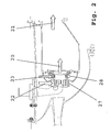
- FIG 3 shows a first embodiment, in which the feed tubes 24 for the Fuel from the outside into the atomizer 6 or into one open ring channel unspecified.
- the little arrows each show the direction of exit of the fuel jets through the outlet openings 16. This results in also the optional angular adjustment of the center lines the outlet openings 16 for the fuel.
- Fig. 4 shows an embodiment, similar to the illustration 3, also an enlarged area is shown in the circle section. It can be seen that the fuel supply tube 24 into an outlet opening 16 opens out from which fuel with an orientation partially against the direction of flow in the air mass flow is injected. This will fuel in the inner air flow channel introduced.
- a further outlet opening branches from the fuel supply tube 24 19 from which fuel in the outer Air flow channel is injected.
- the two injection directions of the fuel are marked by arrows.
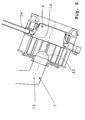
- Fig. 5 shows a further embodiment of an inventive Fuel nozzle at which the decentralized Fuel injection through the outlet openings 16 with a central fuel injection 15 is combined. It there is a separate fuel supply to the outlet openings 16 or the central fuel injection 15th
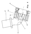
- FIG. 6 Another embodiment is shown in FIG. 6.
- a combination of central fuel injection takes place 15 in the area of the nozzle axis 14 with a decentralized fuel injection through outlet openings 16 at the peripheral area, but schematically the fuel supplies for the central fuel injection 15 and for decentralized fuel injection through outlet openings 16 done by a common burner arm 17.
- Fig. 7 shows a further embodiment with the Combination of a central fuel injection 15 in the area the nozzle axis with a decentralized fuel injection through outlet openings 16 on the peripheral region, wherein however, the central fuel injection 15 with one additional pilot swirl body 25 and a pilot nozzle 26 from decentralized fuel injection is spatially separated by outlet openings 16.
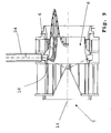
- FIG. 8 shows a modified embodiment of a fuel nozzle according to the invention in side sectional view.
- a central fuel line 13 extend outwardly directed feed tubes 12.
- the arrangement is symmetrical to the nozzle axis 14 designed.
- they each have one at their free end Fuel outlet opening through which the fuel in the area of the outer wall of the atomizer 6 can be applied.
- Fig. 8 In the embodiment shown in Fig. 8 are total six feed tubes 12 are provided.
- the invention provides both the fuel in areas with the highest air flow velocities as an alternative to this in areas with the highest local air mass flows.
- optimized the density ratios or the like become.
- the density of the air is the same, so the largest air mass flows also the largest air flow velocities to have.
- FIG. 2--7 shows configurations in which feed tubes are provided are provided with appropriate outlet openings are. It is understood that, as already mentioned above, suitable nozzles can also be provided (for example the outlet openings 16 in the embodiment 9) to fuel jets or fuel sprays in the free air flow. It is not required that the supply tubes in the air flow cross section protrude or flow there. It is rather, the fuel is possible through the nozzles that are in the Embodiments also referred to as openings 16 and are shown to apply.
- An air-fuel mixer is thus characterized characterized that he with an air content of more than 40% of the total combustion chamber air flows through and through a flow divider into a primary air duct and a Secondary air duct is divided, the primary air duct with an air content of at least 30% of the total Mixer air flows through.
- the secondary air duct envelops due to its radially outer position, the primary air duct.
- the Flow divider shapes the primary flow by its contour and by the ratio of the exit area of the swirl body to the outlet surface of the flow divider certain acceleration on, on the other hand by the flow divider into the primary flow of liquid
- Fuel from inlet openings that extend over the inner circumference of the flow divider are introduced. alternative the fuel is fed from a central supply one or more supply tubes in the primary air duct in the introduced in the immediate area of the flow divider.
- the fuel can also enter the secondary air duct be introduced.
- the air of the primary air duct is axial or diagonal (combined radial and axial) Swirl body swirled.
- the air of the secondary air duct is radial, axial or diagonal (combined radial and axial) swirl body twisted.
- the inlet openings can either be a single jet or individual spray.
- the entry openings are single-row or multi-row.
- the openings about the scope can be the same size or different Size and with any distribution over the circumference be executed.
- the fuel can also over same or different feed tubes are introduced become.
- the difference can affect the Execution of the feed tubes like the shape, the length, the Alignment, the curvature, the execution of the outlet opening such as hole size or hole shape and / or the position of the outlet opening relative to the flow divider.
- the mixer can be operated in combination with a Pilot burner implemented within the primary air duct and is operated at partial load conditions.
- the mixer can also be operated in combination with a pilot burner and a pilot swirl inside of the primary air duct is implemented and by a flow divider is separated from the primary flow.
- the pilot airflow can by an axial, radial or diagonal swirl body can be swirled.
- the fuel injection is preferably carried out with a device for active cooling and / or with a device for Air purge for emptying.
Landscapes
- Engineering & Computer Science (AREA)
- Chemical & Material Sciences (AREA)
- Combustion & Propulsion (AREA)
- Mechanical Engineering (AREA)
- General Engineering & Computer Science (AREA)
- Nozzles For Spraying Of Liquid Fuel (AREA)
Abstract
Description
- Fig. 1
- eine schematische Schnittansicht einer erfindungsgemäßen Gasturbinenbrennkammer,
- Fig. 2
- eine schematische Darstellung der Luftverteilung einer schadstoffarmen Gasturbinenbrennkammer,
- Fig. 3
- eine Seiten-Schnittansicht eines ersten Ausführungsbeispiels einer erfindungsgemäßen Kraftstoffdüse mit dezentraler Einspritzung (sowie vergrößerter Detaildarstellung hierzu),
- Fig. 4
- eine Seiten-Schnittansicht, analog Fig. 3, eines weiteren Ausführungsbeispiels einer Kraftstoffdüse mit Einspritzung des Kraftstoffs in den inneren (Primärluftkanal)und den äußeren Strömungskanal (Sekundärluftkanal),
- Fig. 5
- eine Seiten-Schnittansicht eines weiteren Ausführungsbeispiels einer Kraftstoffdüse bei Kombination mit zentraler und dezentraler Einspritzung mit separater Kraftstoffzufuhr,
- Fig. 6
- eine Schnittansicht, ähnlich Fig. 3 oder 4, eines weiteren Ausführungsbeispiels einer Kraftstoffdüse mit Kombination einer zentralen und dezentralen Einspritzung mit gemeinsamer Kraftstoffzufuhr,
- Fig. 7
- eine Seiten-Schnittansicht eines weiteren Ausführungsbeispiels einer Kraftstoffdüse, ähnlich Fig. 5, bei Kombination mit zentraler und dezentraler Einspritzung mit separater Kraftstoffzufuhr und separater Luftführung,
- Fig. 8
- eine Seiten-Schnittansicht, analog Fig. 3, eines weiteren Ausführungsbeispiels einer Kraftstoffdüse,
- Fig. 9
- eine schematische Seiten-Schnittansicht einer Kraftstoffdüse ähnlich Fig. 3 mit Darstellung der Geschwindigkeitsverteilung der Luftströmung am Düsenaustritt sowie der Kraftstoffströmung.
- 1
- Abdeckung des Brennkopfes
- 2
- Grundplatte
- 3
- Starterfilm
- 4
- Brennkammerwand
- 5
- Hitzeschild mit Loch für Brenner 7
- 6
- Zerstäuber
- 7
- Brenner mit Brennerarm und Drallerzeuger
- 8
- Turbinenleitschaufel
- 9
- Leitschaufel im Verdichterauslass
- 10
- Brennkammeraußengehäuse
- 11
- Brennkammerinnengehäuse
- 12
- Zuführröhre (Kraftstoffleitung)
- 13
- zentrale Kraftstoffleitung
- 14
- Düsenachse
- 15
- zentrale Kraftstoffeinspritzung
- 16
- Austrittsöffnung (Düse)
- 17
- Brennerarm
- 18
- Kraftstoffleitung
- 19
- Austrittsöffnung
- 20
- Düsenluftmassenstrom
- 21
- Austrittsmassenstrom
- 22
- Primärluftkanal
- 23
- Sekundärluftkanal
- 24
- Zuführröhre
- 25
- Pilotierungsdrallkörper
- 26
- Pilotierungsdüse
- 27
- Primärkanaldrallkörper
- 28
- Sekundärkanaldrallkörper
Claims (18)
- Gasturbinenbrennkammer mit einem Brenner (7) und Mitteln zur Kraftstoffzufuhr sowie einem Zerstäuber (6), dadurch gekennzeichnet, dass die Mittel zur Kraftstoffzufuhr zur Einspritzung des Kraftstoffs in Bereiche mit größten Luftströmungsgeschwindigkeiten ausgebildet sind.
- Gasturbinenbrennkammer mit einem Brenner (7) und Mitteln zur Kraftstoffzufuhr sowie einem Zerstäuber (6), dadurch gekennzeichnet, dass die Mittel zur Kraftstoffzufuhr zur Einspritzung des Kraftstoffs in Bereiche mit höchsten lokalen Luftmassenströmen ausgebildet sind.
- Gasturbinenbrennkammer nach Anspruch 1 oder 2, dadurch gekennzeichnet, dass ein Primärluftkanal (22) des Brenners (7) der Brennkammer einen Großteil der für die Mischung und Verbrennung notwendigen Luft zuführt.
- Gasturbinenbrennkammer nach einem der Ansprüche 1 bis 3, dadurch gekennzeichnet, dass die Mittel zur Kraftstoffzufuhr einzelne, in den freien Querschnitt des Zerstäubers (6) ragende Zuführröhren (12) und/ oder Austrittsöffnungen (16) umfassen.
- Gasturbinenbrennkammer nach einem der Ansprüche 1 bis 4, dadurch gekennzeichnet, dass die Zuführröhren (12) und/oder die Austrittsöffnungen (16) von außen in den Bereich der Luftströmung münden.
- Gasturbinenbrennkammer nach Anspruch 5, dadurch gekennzeichnet, dass die Zuführröhren (12) und/ oder die Austrittsöffnungen (16) mit einer zentralen Kraftstoffeinspritzung (15) kombiniert sind.
- Gasturbinenbrennkammer nach einem der Ansprüche 1 bis 6, dadurch gekennzeichnet, dass die Zuführröhren (12) und/oder die Austrittsöffnungen (16) einreihig angeordnet sind.
- Gasturbinenbrennkammer nach einem der Ansprüche 1 bis 7, dadurch gekennzeichnet, dass die Zuführröhren (12) und/oder die Austrittsöffnungen (16) mehrreihig angeordnet sind.
- Gasturbinenbrennkammer nach einem der Ansprüche 1 bis 8, dadurch gekennzeichnet, dass die Zuführröhren (12) und/oder die Austrittsöffnungen (16) mit unterschiedlichen Austrittsdurchmessern ausgebildet sind.
- Gasturbinenbrennkammer nach einem der Ansprüche 1 bis 9, dadurch gekennzeichnet, dass die Zuführröhren (12) und/oder die Austrittsöffnungen (16) in unterschiedlichen Anordnungen angeordnet sind.
- Gasturbinenbrennkammer nach einem der Ansprüche 1 bis 10, dadurch gekennzeichnet, dass die Zuführröhren (12) und/oder die Austrittsöffnungen (16) eine Vorrichtung zur aktiven Kühlung umfassen.
- Gasturbinenbrennkammer nach einem der Ansprüche 1 bis 11, dadurch gekennzeichnet, dass die Zuführröhren (12) und/oder die Austrittsöffnungen (16) eine Vorrichtung zur Spülung durch Luft zur Entleerung aufweisen.
- Gasturbinenbrennkammer nach einem der Ansprüche 1 bis 12, dadurch gekennzeichnet, dass die Zuführröhren (12) von einer zentralen Kraftstoffleitung (13) aus strahlenförmig angeordnet sind.
- Gasturbinenbrennkammer nach einem der Ansprüche 1 bis 13, dadurch gekennzeichnet, dass die Zuführröhren (12) aerodynamisch gestaltet oder profiliert ausgebildet sind.
- Gasturbinenbrennkammer nach einem der Ansprüche 1 bis 13, dadurch gekennzeichnet, dass die Zuführröhren (12) radial und/oder axial zur Düsenachse (14) verlaufen.
- Gasturbinenbrennkammer nach einem der Ansprüche 1 bis 15, dadurch gekennzeichnet, dass die Düsen (16) mit einer zentralen Kraftstoffeinspritzung (15) kombiniert sind.
- Gasturbinenbrennkammer nach einem der Ansprüche 2 bis 16, dadurch gekennzeichnet, dass die Einspritzung des Kraftstoffs in den die größte Luftmenge führenden Primärluftkanal (22) erfolgt.
- Gasturbinenbrennkammer nach einem der Ansprüche 1 bis 17, dadurch gekennzeichnet, dass zentrisch ein Pilotierungsdrallkörper (25) mit einer Pilotierungsdüse (26) zur zentrischen Kraftstoffeinspritzung angeordnet ist.
Applications Claiming Priority (2)
| Application Number | Priority Date | Filing Date | Title |
|---|---|---|---|
| DE10219354A DE10219354A1 (de) | 2002-04-30 | 2002-04-30 | Gasturbinenbrennkammer mit gezielter Kraftstoffeinbringung zur Verbesserung der Homogenität des Kraftstoff-Luft-Gemisches |
| DE10219354 | 2002-04-30 |
Publications (3)
| Publication Number | Publication Date |
|---|---|
| EP1359376A2 true EP1359376A2 (de) | 2003-11-05 |
| EP1359376A3 EP1359376A3 (de) | 2005-03-30 |
| EP1359376B1 EP1359376B1 (de) | 2010-06-16 |
Family
ID=28798942
Family Applications (1)
| Application Number | Title | Priority Date | Filing Date |
|---|---|---|---|
| EP03009434A Expired - Lifetime EP1359376B1 (de) | 2002-04-30 | 2003-04-25 | Gasturbinenbrennkammer mit gezielter Kraftstoffeinbringung zur Verbesserung der Homogenität des Kraftstoff-Luft-Gemisches |
Country Status (3)
| Country | Link |
|---|---|
| US (1) | US7086234B2 (de) |
| EP (1) | EP1359376B1 (de) |
| DE (2) | DE10219354A1 (de) |
Cited By (5)
| Publication number | Priority date | Publication date | Assignee | Title |
|---|---|---|---|---|
| DE102007050276A1 (de) * | 2007-10-18 | 2009-04-23 | Rolls-Royce Deutschland Ltd & Co Kg | Magervormischbrenner für ein Gasturbinentriebwerk |
| EP1512912A3 (de) * | 2003-09-04 | 2010-10-27 | Rolls-Royce Deutschland Ltd & Co KG | Homogene Gemischbildung durch verdrallte Einspritzung des Kraftstoffs |
| EP2103876A3 (de) * | 2008-03-18 | 2013-07-03 | Rolls-Royce Deutschland Ltd & Co KG | Brenner für Gasturbine mit Spülmechanismus für die Brennstoffdüse |
| EP2703721A1 (de) * | 2012-08-31 | 2014-03-05 | Alstom Technology Ltd | Vormischbrenner |
| CN112815355A (zh) * | 2021-01-19 | 2021-05-18 | 重庆交通大学绿色航空技术研究院 | 小型涡轮发动机的火焰稳定装置及涡轮发动机 |
Families Citing this family (13)
| Publication number | Priority date | Publication date | Assignee | Title |
|---|---|---|---|---|
| DE10348604A1 (de) * | 2003-10-20 | 2005-07-28 | Rolls-Royce Deutschland Ltd & Co Kg | Kraftstoffeinspritzdüse mit filmartiger Kraftstoffplatzierung |
| US20070028595A1 (en) * | 2005-07-25 | 2007-02-08 | Mongia Hukam C | High pressure gas turbine engine having reduced emissions |
| GB2444737B (en) * | 2006-12-13 | 2009-03-04 | Siemens Ag | Improvements in or relating to burners for a gas turbine engine |
| US8117845B2 (en) * | 2007-04-27 | 2012-02-21 | General Electric Company | Systems to facilitate reducing flashback/flame holding in combustion systems |
| DE102007043626A1 (de) | 2007-09-13 | 2009-03-19 | Rolls-Royce Deutschland Ltd & Co Kg | Gasturbinenmagerbrenner mit Kraftstoffdüse mit kontrollierter Kraftstoffinhomogenität |
| US8371101B2 (en) * | 2009-09-15 | 2013-02-12 | General Electric Company | Radial inlet guide vanes for a combustor |
| IT1399989B1 (it) * | 2010-05-05 | 2013-05-09 | Avio Spa | Gruppo di iniezione per un combustore di una turbina a gas |
| US20130067923A1 (en) * | 2011-09-20 | 2013-03-21 | General Electric Company | Combustor and method for conditioning flow through a combustor |
| US20130233349A1 (en) * | 2012-03-06 | 2013-09-12 | General Electric Company | Systems and Methods to Clean Gas Turbine Fuel Chamber Components |
| US10041679B2 (en) * | 2015-06-24 | 2018-08-07 | Delavan Inc | Combustion systems |
| CN105864826B (zh) * | 2016-04-26 | 2018-08-31 | 中国科学院工程热物理研究所 | 一种文丘里管尾缘结构 |
| US10502425B2 (en) * | 2016-06-03 | 2019-12-10 | General Electric Company | Contoured shroud swirling pre-mix fuel injector assembly |
| FR3057648B1 (fr) * | 2016-10-18 | 2021-06-11 | Safran Helicopter Engines | Systeme d'injection pauvre de chambre de combustion de turbomachine |
Citations (1)
| Publication number | Priority date | Publication date | Assignee | Title |
|---|---|---|---|---|
| EP0935095A2 (de) | 1998-02-09 | 1999-08-11 | Mitsubishi Heavy Industries, Ltd. | Gasturbinenbrennkammer |
Family Cites Families (55)
| Publication number | Priority date | Publication date | Assignee | Title |
|---|---|---|---|---|
| US3568650A (en) * | 1968-12-05 | 1971-03-09 | Sonic Air Inc | Supercharger and fuel injector assembly for internal combustion engines |
| US3699773A (en) * | 1968-12-23 | 1972-10-24 | Gen Electric | Fuel cooled fuel injectors |
| US3713588A (en) * | 1970-11-27 | 1973-01-30 | Gen Motors Corp | Liquid fuel spray nozzles with air atomization |
| US3703259A (en) * | 1971-05-03 | 1972-11-21 | Gen Electric | Air blast fuel atomizer |
| US3866413A (en) * | 1973-01-22 | 1975-02-18 | Parker Hannifin Corp | Air blast fuel atomizer |
| US3808803A (en) * | 1973-03-15 | 1974-05-07 | Us Navy | Anticarbon device for the scroll fuel carburetor |
| US3919840A (en) * | 1973-04-18 | 1975-11-18 | United Technologies Corp | Combustion chamber for dissimilar fluids in swirling flow relationship |
| US3980233A (en) * | 1974-10-07 | 1976-09-14 | Parker-Hannifin Corporation | Air-atomizing fuel nozzle |
| DE2529701A1 (de) * | 1975-07-03 | 1977-01-27 | Bosch Gmbh Robert | Kraftstoffeinspritzanlage |
| US3977186A (en) * | 1975-07-24 | 1976-08-31 | General Motors Corporation | Impinging air jet combustion apparatus |
| GB1597968A (en) * | 1977-06-10 | 1981-09-16 | Rolls Royce | Fuel burners for gas turbine engines |
| GB2012415B (en) * | 1978-01-04 | 1982-03-03 | Secr Defence | Fuel mixers |
| US4175380A (en) * | 1978-03-24 | 1979-11-27 | Baycura Orestes M | Low noise gas turbine |
| IT1111808B (it) * | 1978-03-28 | 1986-01-13 | Rolls Royce | Perfezionamenti apportati ai dispositivi di combustione di motori a turbina a gas |
| US4519958A (en) * | 1982-06-14 | 1985-05-28 | Kenna Research Corporation | Fuel flow metering apparatus |
| US4845952A (en) * | 1987-10-23 | 1989-07-11 | General Electric Company | Multiple venturi tube gas fuel injector for catalytic combustor |
| US4854127A (en) * | 1988-01-14 | 1989-08-08 | General Electric Company | Bimodal swirler injector for a gas turbine combustor |
| CH680084A5 (de) * | 1989-06-06 | 1992-06-15 | Asea Brown Boveri | |
| JP2839777B2 (ja) * | 1991-12-24 | 1998-12-16 | 株式会社東芝 | ガスタービン燃焼器用燃料噴射ノズル |
| US5251447A (en) * | 1992-10-01 | 1993-10-12 | General Electric Company | Air fuel mixer for gas turbine combustor |
| DE4304213A1 (de) * | 1993-02-12 | 1994-08-18 | Abb Research Ltd | Brenner zum Betrieb einer Brennkraftmaschine, einer Brennkammer einer Gasturbogruppe oder Feuerungsanlage |
| JPH06272862A (ja) * | 1993-03-18 | 1994-09-27 | Hitachi Ltd | 燃料空気混合方法およびその混合装置 |
| US5511375A (en) | 1994-09-12 | 1996-04-30 | General Electric Company | Dual fuel mixer for gas turbine combustor |
| US5590529A (en) * | 1994-09-26 | 1997-01-07 | General Electric Company | Air fuel mixer for gas turbine combustor |
| DE4446611A1 (de) * | 1994-12-24 | 1996-06-27 | Abb Management Ag | Brennkammer |
| US5701732A (en) * | 1995-01-24 | 1997-12-30 | Delavan Inc. | Method and apparatus for purging of gas turbine injectors |
| DE69625744T2 (de) * | 1995-06-05 | 2003-10-16 | Rolls-Royce Corp., Indianapolis | Magervormischbrenner mit niedrigem NOx-Ausstoss für industrielle Gasturbinen |
| DE19527453B4 (de) * | 1995-07-27 | 2009-05-07 | Alstom | Vormischbrenner |
| DE19535370B4 (de) * | 1995-09-25 | 2006-05-11 | Alstom | Verfahren zur schadstoffarmen Vormischverbrennung in Gasturbinenbrennkammern |
| US5778676A (en) * | 1996-01-02 | 1998-07-14 | General Electric Company | Dual fuel mixer for gas turbine combustor |
| US5916142A (en) * | 1996-10-21 | 1999-06-29 | General Electric Company | Self-aligning swirler with ball joint |
| US5927076A (en) * | 1996-10-22 | 1999-07-27 | Westinghouse Electric Corporation | Multiple venturi ultra-low nox combustor |
| GB2324147B (en) * | 1997-04-10 | 2001-09-05 | Europ Gas Turbines Ltd | Fuel-injection arrangement for a gas turbine combuster |
| EP1009952A4 (de) * | 1997-05-13 | 2001-05-02 | Maxon Corp | INDUSTRIEBRENNER MIT GERINGEN NOx-EMISSIONEN |
| JP3448190B2 (ja) * | 1997-08-29 | 2003-09-16 | 三菱重工業株式会社 | ガスタービンの燃焼器 |
| US5983642A (en) * | 1997-10-13 | 1999-11-16 | Siemens Westinghouse Power Corporation | Combustor with two stage primary fuel tube with concentric members and flow regulating |
| DE19757189B4 (de) | 1997-12-22 | 2008-05-08 | Alstom | Verfahren zum Betrieb eines Brenners eines Wärmeerzeugers |
| US6122916A (en) * | 1998-01-02 | 2000-09-26 | Siemens Westinghouse Power Corporation | Pilot cones for dry low-NOx combustors |
| ITMI991204A1 (it) * | 1999-05-31 | 2000-12-01 | Nuovo Pignone Spa | Iniettore di combustibile liquido per bruciatori in turbine a gas |
| JP3364169B2 (ja) * | 1999-06-09 | 2003-01-08 | 三菱重工業株式会社 | ガスタービン及びその燃焼器 |
| IT1313547B1 (it) * | 1999-09-23 | 2002-07-24 | Nuovo Pignone Spa | Camera di premiscelamento per turbine a gas |
| JP2001263143A (ja) * | 2000-03-16 | 2001-09-26 | Hitachi Ltd | 内燃機関の制御装置 |
| US6481209B1 (en) * | 2000-06-28 | 2002-11-19 | General Electric Company | Methods and apparatus for decreasing combustor emissions with swirl stabilized mixer |
| JP2002031343A (ja) * | 2000-07-13 | 2002-01-31 | Mitsubishi Heavy Ind Ltd | 燃料噴出部材、バーナ、燃焼器の予混合ノズル、燃焼器、ガスタービン及びジェットエンジン |
| US6460345B1 (en) * | 2000-11-14 | 2002-10-08 | General Electric Company | Catalytic combustor flow conditioner and method for providing uniform gasvelocity distribution |
| US6453660B1 (en) * | 2001-01-18 | 2002-09-24 | General Electric Company | Combustor mixer having plasma generating nozzle |
| US6539724B2 (en) * | 2001-03-30 | 2003-04-01 | Delavan Inc | Airblast fuel atomization system |
| US20020162333A1 (en) * | 2001-05-02 | 2002-11-07 | Honeywell International, Inc., Law Dept. Ab2 | Partial premix dual circuit fuel injector |
| GB2375601A (en) * | 2001-05-18 | 2002-11-20 | Siemens Ag | Burner apparatus for reducing combustion vibrations |
| US6418726B1 (en) * | 2001-05-31 | 2002-07-16 | General Electric Company | Method and apparatus for controlling combustor emissions |
| US6691516B2 (en) * | 2002-07-15 | 2004-02-17 | Power Systems Mfg, Llc | Fully premixed secondary fuel nozzle with improved stability |
| US6675581B1 (en) * | 2002-07-15 | 2004-01-13 | Power Systems Mfg, Llc | Fully premixed secondary fuel nozzle |
| US6722132B2 (en) * | 2002-07-15 | 2004-04-20 | Power Systems Mfg, Llc | Fully premixed secondary fuel nozzle with improved stability and dual fuel capability |
| US6705087B1 (en) * | 2002-09-13 | 2004-03-16 | Siemens Westinghouse Power Corporation | Swirler assembly with improved vibrational response |
| ES2309128T3 (es) * | 2002-09-20 | 2008-12-16 | Siemens Aktiengesellschaft | Quemador premezclado con corriente masica de aire perfilada, turbina de gas y procedimiento para quemar combustible en aire. |
-
2002
- 2002-04-30 DE DE10219354A patent/DE10219354A1/de not_active Withdrawn
-
2003
- 2003-04-25 DE DE50312809T patent/DE50312809D1/de not_active Expired - Lifetime
- 2003-04-25 EP EP03009434A patent/EP1359376B1/de not_active Expired - Lifetime
- 2003-05-05 US US10/429,236 patent/US7086234B2/en not_active Expired - Lifetime
Patent Citations (1)
| Publication number | Priority date | Publication date | Assignee | Title |
|---|---|---|---|---|
| EP0935095A2 (de) | 1998-02-09 | 1999-08-11 | Mitsubishi Heavy Industries, Ltd. | Gasturbinenbrennkammer |
Cited By (7)
| Publication number | Priority date | Publication date | Assignee | Title |
|---|---|---|---|---|
| EP1512912A3 (de) * | 2003-09-04 | 2010-10-27 | Rolls-Royce Deutschland Ltd & Co KG | Homogene Gemischbildung durch verdrallte Einspritzung des Kraftstoffs |
| DE102007050276A1 (de) * | 2007-10-18 | 2009-04-23 | Rolls-Royce Deutschland Ltd & Co Kg | Magervormischbrenner für ein Gasturbinentriebwerk |
| US8910483B2 (en) | 2007-10-18 | 2014-12-16 | Rolls-Royce Deutschland Ltd & C | Lean premix burner for a gas-turbine engine |
| EP2103876A3 (de) * | 2008-03-18 | 2013-07-03 | Rolls-Royce Deutschland Ltd & Co KG | Brenner für Gasturbine mit Spülmechanismus für die Brennstoffdüse |
| EP2703721A1 (de) * | 2012-08-31 | 2014-03-05 | Alstom Technology Ltd | Vormischbrenner |
| US9400105B2 (en) | 2012-08-31 | 2016-07-26 | General Electric Technology Gmbh | Premix burner |
| CN112815355A (zh) * | 2021-01-19 | 2021-05-18 | 重庆交通大学绿色航空技术研究院 | 小型涡轮发动机的火焰稳定装置及涡轮发动机 |
Also Published As
| Publication number | Publication date |
|---|---|
| DE10219354A1 (de) | 2003-11-13 |
| US20040040311A1 (en) | 2004-03-04 |
| DE50312809D1 (de) | 2010-07-29 |
| US7086234B2 (en) | 2006-08-08 |
| EP1359376B1 (de) | 2010-06-16 |
| EP1359376A3 (de) | 2005-03-30 |
Similar Documents
| Publication | Publication Date | Title |
|---|---|---|
| DE69412484T2 (de) | Verbrennungskammer eines gasturbinenmotors | |
| DE60310170T2 (de) | Brennstoffinjektionsvorrichtung | |
| EP1359376B1 (de) | Gasturbinenbrennkammer mit gezielter Kraftstoffeinbringung zur Verbesserung der Homogenität des Kraftstoff-Luft-Gemisches | |
| DE69513542T2 (de) | Brennstoffdüse | |
| DE69911008T2 (de) | Gasturbinenkraftstoffeinspritzdüse | |
| DE3017034C2 (de) | ||
| DE69410424T2 (de) | Brennstoff-Einspritzvorrichtung | |
| DE69500969T2 (de) | Vormischung für ein Einspritzsystem | |
| EP1802915B1 (de) | Brenner für gasturbine | |
| DE69519849T2 (de) | Brennstoffdüse mit tangentialer einspritzung | |
| EP2156095B1 (de) | Drallfreie stabilisierung der flamme eines vormischbrenners | |
| DE69721626T2 (de) | Gasturbinenbrennkamer | |
| DE69525920T2 (de) | Brennstoffeinspritzeinrictung für mit gasförmigem oder flüssigem Brennstoff betriebene Turbine | |
| DE69617290T2 (de) | Verbrennungsgerät für Gasturbinenmotor | |
| DE102010060281A1 (de) | Vormischvorrichtung zur Brennstoffeinspritzung in eine Gasturbine | |
| EP0629817B1 (de) | Feuerungsanlage | |
| CH697908A2 (de) | Brennstoffverteiler für DNL-Gasturbinen. | |
| DE3889370T2 (de) | Druckluftzerstäuber für Brennstoff. | |
| DE102007046623A1 (de) | Flüssigbrennstoffverbesserung für drallstabilisierte Erdgasdüse und Verfahren | |
| EP2513562B1 (de) | Brenner für eine turbine | |
| DE602005001742T2 (de) | Aerodynamisches aufschäumendes Brennstoff/Luft Einspritzungssystem für eine Gasturbinenbrennkammer | |
| EP1512912A2 (de) | Homogene Gemischbildung durch verdrallte Einspritzung des Kraftstoffs | |
| EP0347834A2 (de) | Brennerkopf für einen Gebläsegasbrenner | |
| EP0762057B1 (de) | Einrichtung zur Vermischung von Brennstoff und Luft für Brennkammern von Gasturbinentriebwerken | |
| DE69605813T2 (de) | Brennstoff-einspritzeinrichtung für verbrennungsgerät |
Legal Events
| Date | Code | Title | Description |
|---|---|---|---|
| PUAI | Public reference made under article 153(3) epc to a published international application that has entered the european phase |
Free format text: ORIGINAL CODE: 0009012 |
|
| AK | Designated contracting states |
Kind code of ref document: A2 Designated state(s): AT BE BG CH CY CZ DE DK EE ES FI FR GB GR HU IE IT LI LU MC NL PT RO SE SI SK TR |
|
| AX | Request for extension of the european patent |
Extension state: AL LT LV MK |
|
| PUAL | Search report despatched |
Free format text: ORIGINAL CODE: 0009013 |
|
| AK | Designated contracting states |
Kind code of ref document: A3 Designated state(s): AT BE BG CH CY CZ DE DK EE ES FI FR GB GR HU IE IT LI LU MC NL PT RO SE SI SK TR |
|
| AX | Request for extension of the european patent |
Extension state: AL LT LV MK |
|
| 17P | Request for examination filed |
Effective date: 20050504 |
|
| AKX | Designation fees paid |
Designated state(s): DE FR GB |
|
| 17Q | First examination report despatched |
Effective date: 20060714 |
|
| GRAP | Despatch of communication of intention to grant a patent |
Free format text: ORIGINAL CODE: EPIDOSNIGR1 |
|
| GRAS | Grant fee paid |
Free format text: ORIGINAL CODE: EPIDOSNIGR3 |
|
| RIN1 | Information on inventor provided before grant (corrected) |
Inventor name: LAZIK, WALDEMAR, DIPL.-ING. Inventor name: DOERR, THOMAS, DR.-ING. |
|
| GRAA | (expected) grant |
Free format text: ORIGINAL CODE: 0009210 |
|
| AK | Designated contracting states |
Kind code of ref document: B1 Designated state(s): DE FR GB |
|
| REF | Corresponds to: |
Ref document number: 50312809 Country of ref document: DE Date of ref document: 20100729 Kind code of ref document: P |
|
| PLBE | No opposition filed within time limit |
Free format text: ORIGINAL CODE: 0009261 |
|
| STAA | Information on the status of an ep patent application or granted ep patent |
Free format text: STATUS: NO OPPOSITION FILED WITHIN TIME LIMIT |
|
| 26N | No opposition filed |
Effective date: 20110317 |
|
| REG | Reference to a national code |
Ref country code: DE Ref legal event code: R097 Ref document number: 50312809 Country of ref document: DE Effective date: 20110316 |
|
| REG | Reference to a national code |
Ref country code: DE Ref legal event code: R082 Ref document number: 50312809 Country of ref document: DE Representative=s name: HOEFER & PARTNER, DE |
|
| REG | Reference to a national code |
Ref country code: DE Ref legal event code: R082 Ref document number: 50312809 Country of ref document: DE Representative=s name: HOEFER & PARTNER, DE Effective date: 20130402 Ref country code: DE Ref legal event code: R081 Ref document number: 50312809 Country of ref document: DE Owner name: ROLLS-ROYCE DEUTSCHLAND LTD & CO KG, DE Free format text: FORMER OWNER: ROLLS-ROYCE DEUTSCHLAND LTD & CO KG, 15827 BLANKENFELDE, DE Effective date: 20130402 Ref country code: DE Ref legal event code: R082 Ref document number: 50312809 Country of ref document: DE Representative=s name: HOEFER & PARTNER PATENTANWAELTE MBB, DE Effective date: 20130402 |
|
| REG | Reference to a national code |
Ref country code: FR Ref legal event code: PLFP Year of fee payment: 14 |
|
| REG | Reference to a national code |
Ref country code: FR Ref legal event code: PLFP Year of fee payment: 15 |
|
| PGFP | Annual fee paid to national office [announced via postgrant information from national office to epo] |
Ref country code: FR Payment date: 20170426 Year of fee payment: 15 Ref country code: GB Payment date: 20170427 Year of fee payment: 15 Ref country code: DE Payment date: 20170427 Year of fee payment: 15 |
|
| REG | Reference to a national code |
Ref country code: DE Ref legal event code: R082 Ref document number: 50312809 Country of ref document: DE |
|
| REG | Reference to a national code |
Ref country code: DE Ref legal event code: R119 Ref document number: 50312809 Country of ref document: DE |
|
| GBPC | Gb: european patent ceased through non-payment of renewal fee |
Effective date: 20180425 |
|
| PG25 | Lapsed in a contracting state [announced via postgrant information from national office to epo] |
Ref country code: DE Free format text: LAPSE BECAUSE OF NON-PAYMENT OF DUE FEES Effective date: 20181101 |
|
| PG25 | Lapsed in a contracting state [announced via postgrant information from national office to epo] |
Ref country code: GB Free format text: LAPSE BECAUSE OF NON-PAYMENT OF DUE FEES Effective date: 20180425 |
|
| PG25 | Lapsed in a contracting state [announced via postgrant information from national office to epo] |
Ref country code: FR Free format text: LAPSE BECAUSE OF NON-PAYMENT OF DUE FEES Effective date: 20180430 |