EP1359113A2 - Flurförderzeug mit einer Vorrichtung zum Bewegen eines Hubgerüsts - Google Patents
Flurförderzeug mit einer Vorrichtung zum Bewegen eines Hubgerüsts Download PDFInfo
- Publication number
- EP1359113A2 EP1359113A2 EP03007553A EP03007553A EP1359113A2 EP 1359113 A2 EP1359113 A2 EP 1359113A2 EP 03007553 A EP03007553 A EP 03007553A EP 03007553 A EP03007553 A EP 03007553A EP 1359113 A2 EP1359113 A2 EP 1359113A2
- Authority
- EP
- European Patent Office
- Prior art keywords
- mast
- truck
- movement
- operating parameter
- load
- Prior art date
- Legal status (The legal status is an assumption and is not a legal conclusion. Google has not performed a legal analysis and makes no representation as to the accuracy of the status listed.)
- Granted
Links
- 230000001133 acceleration Effects 0.000 claims abstract description 24
- 238000006073 displacement reaction Methods 0.000 claims description 2
- 230000001419 dependent effect Effects 0.000 description 2
- 230000007306 turnover Effects 0.000 description 2
- 238000004364 calculation method Methods 0.000 description 1
- 238000001514 detection method Methods 0.000 description 1
- 238000000034 method Methods 0.000 description 1
- 230000010355 oscillation Effects 0.000 description 1
Images
Classifications
-
- B—PERFORMING OPERATIONS; TRANSPORTING
- B66—HOISTING; LIFTING; HAULING
- B66F—HOISTING, LIFTING, HAULING OR PUSHING, NOT OTHERWISE PROVIDED FOR, e.g. DEVICES WHICH APPLY A LIFTING OR PUSHING FORCE DIRECTLY TO THE SURFACE OF A LOAD
- B66F9/00—Devices for lifting or lowering bulky or heavy goods for loading or unloading purposes
- B66F9/06—Devices for lifting or lowering bulky or heavy goods for loading or unloading purposes movable, with their loads, on wheels or the like, e.g. fork-lift trucks
- B66F9/075—Constructional features or details
- B66F9/20—Means for actuating or controlling masts, platforms, or forks
- B66F9/24—Electrical devices or systems
-
- B—PERFORMING OPERATIONS; TRANSPORTING
- B66—HOISTING; LIFTING; HAULING
- B66F—HOISTING, LIFTING, HAULING OR PUSHING, NOT OTHERWISE PROVIDED FOR, e.g. DEVICES WHICH APPLY A LIFTING OR PUSHING FORCE DIRECTLY TO THE SURFACE OF A LOAD
- B66F9/00—Devices for lifting or lowering bulky or heavy goods for loading or unloading purposes
- B66F9/06—Devices for lifting or lowering bulky or heavy goods for loading or unloading purposes movable, with their loads, on wheels or the like, e.g. fork-lift trucks
- B66F9/075—Constructional features or details
- B66F9/08—Masts; Guides; Chains
- B66F9/082—Masts; Guides; Chains inclinable
-
- B—PERFORMING OPERATIONS; TRANSPORTING
- B66—HOISTING; LIFTING; HAULING
- B66F—HOISTING, LIFTING, HAULING OR PUSHING, NOT OTHERWISE PROVIDED FOR, e.g. DEVICES WHICH APPLY A LIFTING OR PUSHING FORCE DIRECTLY TO THE SURFACE OF A LOAD
- B66F9/00—Devices for lifting or lowering bulky or heavy goods for loading or unloading purposes
- B66F9/06—Devices for lifting or lowering bulky or heavy goods for loading or unloading purposes movable, with their loads, on wheels or the like, e.g. fork-lift trucks
- B66F9/075—Constructional features or details
- B66F9/08—Masts; Guides; Chains
- B66F9/10—Masts; Guides; Chains movable in a horizontal direction relative to truck
Definitions
- the invention relates to an industrial truck with a frame, a mast, a along the mast vertically movable load-carrying means and at least one Movement device for moving the mast relative to the frame.
- the mast by means of a tilting device relative to a Be tilted frame of the truck.
- Reach trucks have additional a pushing device with which the mast horizontally, in the longitudinal direction of Truck can be moved relative to the frame.
- the invention is therefore based on the object, an industrial truck of the beginning be provided with improved handling capacity.
- acceleration and / or the speed of the device that can be generated by means of the movement device Movement of the mast in dependence on at least one operating parameter of the truck can be influenced.
- the operating parameter is with a detected by a suitable measuring instrument and preferably in an electrical signal implemented.
- An electronic control processes the operating parameters and generates from this one for the speed or acceleration of the Lifting equipment is the decisive influencing factor. Possible influencing factors are for example, the maximum speed that can be generated with the movement device or maximum acceleration of the mast.
- acceleration includes in the present context also during braking of the mast occurring braking acceleration.
- the operating parameter is at least approximately infinitely variable detected.
- the infinite detection of the operating parameter makes it possible to Acceleration and / or the speed of the movement device as well vary almost continuously and constantly adapt to the conditions.
- For the present application is considered to be stepless, for example, the Parameter acquisition by means of an incremental encoder.
- An operating parameter is the current lifting height of the load handling device educated.
- a two-channel lifting height sensor is used, the one provides redundant signal. This ensures that the calculation of the speed and / or the acceleration of the mast on no basis on the basis of a wrong Lifting height signal takes place.
- the maximum acceleration and / or the maximum speed of the Movement device producible movement of the mast is dependent on the lift height influenced such that at low lift a stronger Acceleration or a higher speed is possible, than at large Lifting height.
- a second operating parameter is the weight of one with the load handler formed load formed.
- the load weight for example, indirectly over the be determined in a hydraulic lifting cylinder pending pressure. Of the Load weight hang on the acceleration of the lifting device on the Mast forces directly from.
- the maximum acceleration and / or the maximum speed of the Movement device producible movement of the mast is dependent on the weight of the load influenced so that at low weight a stronger Acceleration or higher speed is possible than at high weight.
- the movement device of a tilting device for formed the mast In lowered and unloaded state can thus the Mast tilted faster than in the raised and loaded condition.
- a movement device of a pusher is formed for horizontal displacement of the mast. Moving the Mast relative to the frame of the truck takes place here so faster, the farther the load handler lowered and the lower it is loaded.
- the invention can be used when the truck as Reach truck is designed.
- a reach truck both the Tilting device, as well as the pusher in response to the above Operating parameters are influenced. This will, in comparison with Reach trucks of the prior art, a particularly large increase in Goods turnover performance achieved.
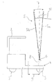
- the figure shows an inventive designed as a reach truck Truck.
- the reach truck has as essential components a frame. 1 and a driver's roof 2, under which the driver's seat of the Reach truck is located. Wheels 3 are on the frame 1 in the area below the driver's seat and attached to Radarmen 4.
- the wheel arms 4 are also Part of the frame 1.
- a telescopically extendable mast 5 can relative to the frame 1 are inclined about a horizontal axis 6. This is shown Mast 5 in its forwardly inclined end position 5a and in his back inclined end position 5b.
- the tilt angle 7 of the mast 5 is usually about 6 degrees.
- Along the mast 5 is designed as a fork Load-receiving means 10 slidably guided.
- the tiltable about the axis 6 storage of the mast 5 takes place on a slide carriage 8.
- the slide carriage 8 is connected to the Radarmen 4 slidably guided in the horizontal direction. Shown is the Thrust carriage 8 in its front end position and can along the push path 9 in Direction of the driver's seat are pushed.
- the drive of the pusher for moving the sliding carriage 8 and thus of the mast 5 along the push path 9 by means of a hydraulic Cylinder includes.
- the hydraulic cylinders are equipped with hydraulic valves Hydraulic pump connected.
- the accelerations and speeds of the Tilting movement and the pushing movement can be controlled by appropriate the hydraulic valves are adjusted. It is also possible, the Accelerations and speeds of said movements over the Speed of a hydraulic motor driving the electric motor to control, which while being supplied with power accordingly.
- This information will be in an electronic Control device of the truck processed, with limits for the Speeds and accelerations of the pushing movement of the sliding carriage. 8 and the tilting movement of the mast 5 are determined. These limits are like this measured that excessive swinging of the mast 5 is prevented.
- the accelerations and speeds are not over the required extent limited, so that the reach truck is an optimal Goods turnover performance achieved.
- the electronic control devices are the Relationships between the determined measured variables and the permissible ones Accelerations and speeds as software, for example in the form of Algorithms or maps deposited.
- control device with the from Driver to operating levers for the tilting device and the Pusher connected.
- the hydraulic valves or the hydraulic pump driving electric motor are by the electronic control device Subject to the control lever positions directly or indirectly controlled, the Accelerations and speeds limited to the maximum values determined become.
Landscapes
- Engineering & Computer Science (AREA)
- Transportation (AREA)
- Structural Engineering (AREA)
- Civil Engineering (AREA)
- Life Sciences & Earth Sciences (AREA)
- Geology (AREA)
- Mechanical Engineering (AREA)
- Chemical & Material Sciences (AREA)
- Combustion & Propulsion (AREA)
- Forklifts And Lifting Vehicles (AREA)
Abstract
Description
Lastaufnahmemittels führen kann. Aus diesem Grund wird bei bekannten Flurförderzeugen die Geschwindigkeit der mit der Bewegungsvorrichtung erzeugbaren Bewegung konstant auf einen niedrigen Wert eingestellt, wodurch ein Schwingen des beladenen und ausgefahrenen Hubgerüsts auf ein zulässiges Maß begrenzt werden kann. Bei abgesenktem und unbeladenem Lastaufnahmemittel gilt für die Geschwindigkeit der mit der Bewegungsvorrichtung erzeugbaren Bewegung derselbe niedrige Wert, obwohl die Gefahr eines Schwingens des Hubgerüsts nicht besteht.
Dies bedeutet, dass die Warenumschlagleistung des Flurförderzeugs über das eigentlich erforderliche Maß hinaus reduziert wird.
Claims (9)
- Flurförderzeug mit einem Rahmen (1), einem Hubgerüst (5), einem entlang des Hubgerüsts (5) vertikal bewegbaren Lastaufnahmemittel (10) und mindestens einer Bewegungsvorrichtung zum Bewegen des Hubgerüsts (5) relativ zu dem Rahmen (1), dadurch gekennzeichnet, dass die Beschleunigung und/oder die Geschwindigkeit der mittels der Bewegungsvorrichtung erzeugbaren Bewegung des Hubgerüsts (5) in Abhängigkeit von mindestens einem Betriebsparameter des Flurförderzeugs beeinflussbar ist.
- Flurförderzeug nach Anspruch 1, dadurch gekennzeichnet, dass der Betriebsparameter zumindest annähernd stufenlos erfasst wird.
- Flurförderzeug nach Anspruch 1 oder 2, dadurch gekennzeichnet, dass ein Betriebsparameter von der aktuellen Hubhöhe des Lastaufnahmemittels (10) gebildet ist.
- Flurförderzeug nach Anspruch 3, dadurch gekennzeichnet, dass die maximale Beschleunigung und/oder die maximale Geschwindigkeit der mittels der Bewegungsvorrichtung erzeugbaren Bewegung des Hubgerüsts (5) in Abhängigkeit von der Hubhöhe derart beeinflussbar ist, dass bei geringer Hubhöhe eine stärkere Beschleunigung oder eine höhere Geschwindigkeit möglich ist, als bei großer Hubhöhe.
- Flurförderzeug nach einem der Ansprüche 1 bis 4, dadurch gekennzeichnet, dass ein Betriebsparameter von dem Gewicht einer mit dem Lastaufnahmemittel (10) aufgenommenen Last gebildet ist.
- Flurförderzeug nach Anspruch 5, dadurch gekennzeichnet, dass die maximale Beschleunigung und/oder die maximale Geschwindigkeit der mittels der Bewegungsvorrichtung erzeugbaren Bewegung des Hubgerüsts (5) in Abhängigkeit von dem Gewicht der Last derart beeinflussbar ist, dass bei geringem Gewicht eine stärkere Beschleunigung oder eine höhere Geschwindigkeit möglich ist, als bei hohem Gewicht.
- Flurförderzeug nach einem der Ansprüche 1 bis 6, dadurch gekennzeichnet, dass eine Bewegungsvorrichtung von einer Neigevorrichtung für das Hubgerüst (5) gebildet ist.
- Flurförderzeug nach einem der Ansprüche 1 bis 7, dadurch gekennzeichnet, dass eine Bewegungsvorrichtung von einer Schubvorrichtung zum horizontalen Verschieben des Hubgerüsts (5) gebildet ist.
- Flurförderzeug nach einem der Ansprüche 1 bis 8, dadurch gekennzeichnet, dass das Flurförderzeug als Schubmaststapler ausgebildet ist.
Applications Claiming Priority (2)
| Application Number | Priority Date | Filing Date | Title |
|---|---|---|---|
| DE10219739A DE10219739A1 (de) | 2002-05-02 | 2002-05-02 | Flurförderzeug mit einer Vorrichtung zum Bewegen eines Hubgerüsts |
| DE10219739 | 2002-05-02 |
Publications (4)
| Publication Number | Publication Date |
|---|---|
| EP1359113A2 true EP1359113A2 (de) | 2003-11-05 |
| EP1359113A3 EP1359113A3 (de) | 2006-05-17 |
| EP1359113B1 EP1359113B1 (de) | 2010-10-06 |
| EP1359113B2 EP1359113B2 (de) | 2018-04-04 |
Family
ID=28798981
Family Applications (1)
| Application Number | Title | Priority Date | Filing Date |
|---|---|---|---|
| EP03007553.5A Expired - Lifetime EP1359113B2 (de) | 2002-05-02 | 2003-04-01 | Flurförderzeug mit einer Vorrichtung zum Bewegen eines Hubgerüsts |
Country Status (4)
| Country | Link |
|---|---|
| US (1) | US6945745B2 (de) |
| EP (1) | EP1359113B2 (de) |
| AT (1) | ATE483665T1 (de) |
| DE (2) | DE10219739A1 (de) |
Families Citing this family (16)
| Publication number | Priority date | Publication date | Assignee | Title |
|---|---|---|---|---|
| US6829835B2 (en) * | 2002-11-21 | 2004-12-14 | Martin Pfeil Trawid-Gmbh | Lifting vehicle |
| US20040154871A1 (en) * | 2003-02-12 | 2004-08-12 | Uwe Allerding | Method for operating a fork-lift truck |
| JP4793134B2 (ja) * | 2005-09-30 | 2011-10-12 | 株式会社豊田自動織機 | フォークリフトの走行制御装置 |
| EP1975115A1 (de) * | 2006-01-16 | 2008-10-01 | Mitsubishi Heavy Industries, Ltd. | Gabelstapler und steuerverfahren zur verhinderung von überschlägen des gabelstaplers |
| DE102007024817B4 (de) | 2007-03-30 | 2021-10-07 | Linde Material Handling Gmbh | Flurförderzeug mit einem Hubgerüst und einem Stellglied zur Kompensation von Schwingungen |
| US20080257651A1 (en) * | 2007-04-23 | 2008-10-23 | Williamson Joel L | Lift truck with productivity enhancing package including variable tilt and vertical masting |
| EP2447203B1 (de) * | 2010-11-01 | 2013-04-17 | BT Products AB | Industriefahrzeug, Verfahren und Computerprogramm zum Steuern eines Industriefahrzeugs |
| EP2857344B1 (de) * | 2013-10-07 | 2016-04-06 | Hyster-Yale Group, Inc. | Schubmaststapler |
| DE102014115152B4 (de) * | 2014-10-17 | 2023-09-28 | Jungheinrich Aktiengesellschaft | Schubmaststapler |
| DE102016124505A1 (de) * | 2016-12-15 | 2018-06-21 | Jungheinrich Aktiengesellschaft | Flurförderzeug mit einer Steuereinheit zur Regelung der Bewegung einer Kolbenstange eines Hydraulikzylinders sowie ein solches Verfahren |
| DE102017103043A1 (de) | 2017-02-15 | 2018-08-16 | Jungheinrich Aktiengesellschaft | Flurförderzeug mit einem Hubgerüst |
| CN112654578B (zh) | 2018-09-13 | 2023-03-14 | 克朗设备公司 | 基于计算负载的工业车辆最大车辆速度控制系统和方法 |
| DE102019206658B4 (de) * | 2019-05-09 | 2026-03-05 | Zf Friedrichshafen Ag | Verfahren und Vorrichtung zur Getriebesteuerung einer Arbeitsmaschine |
| EP4324782B1 (de) * | 2022-08-16 | 2025-03-26 | Palfinger AG | Gabelstapler |
| CN117865007A (zh) * | 2023-03-30 | 2024-04-12 | 沈仕明 | 便捷式消防管道安装举升设备 |
| DE102024124544A1 (de) * | 2024-08-28 | 2026-03-05 | Jungheinrich Aktiengesellschaft | Flurförderzeug und Verfahren zum Betreiben eines Flurförderzeugs |
Family Cites Families (11)
| Publication number | Priority date | Publication date | Assignee | Title |
|---|---|---|---|---|
| CA1113891A (en) * | 1979-06-21 | 1981-12-08 | Gerardus J. Brouwer | Forklift vehicle |
| US4580650A (en) * | 1983-07-28 | 1986-04-08 | Nissan Motor Co., Ltd. | Industrial truck |
| US4538954A (en) * | 1983-12-01 | 1985-09-03 | Harnischfeger Corporation | Stacker crane having narrow mast structure |
| JPH04121996A (ja) † | 1990-09-12 | 1992-04-22 | Aichi Electric Co Ltd | 照明装置及び該装置に用いるインバータ |
| US5244336A (en) * | 1991-09-11 | 1993-09-14 | Riggers Manufacturing Co, Inc. | Mobile lifting apparatus with fork attachment |
| US5217342A (en) * | 1991-10-31 | 1993-06-08 | Martin Grether | Self-loading and unloading forklift truck |
| US5697755A (en) * | 1995-03-03 | 1997-12-16 | Mccauley; Charles A. | Forklift level indicator |
| US6027303A (en) * | 1997-07-18 | 2000-02-22 | Voegeli; Ronald C. | Non-counterweighted lift truck and method of operation |
| AU733362B2 (en) * | 1997-09-30 | 2001-05-10 | Crown Equipment Corporation | Productivity package |
| JP3301416B2 (ja) * | 1999-08-23 | 2002-07-15 | 株式会社豊田自動織機 | 産業車両におけるマスト傾動速度制御装置 |
| DE10054789A1 (de) * | 2000-11-04 | 2002-05-08 | Still Wagner Gmbh & Co Kg | Flurförderzeug mit einem Hubgerüst und einer zusätzlichen Bewegungsvorrichtung für ein Lastaufnahmemittel |
-
2002
- 2002-05-02 DE DE10219739A patent/DE10219739A1/de not_active Withdrawn
-
2003
- 2003-04-01 EP EP03007553.5A patent/EP1359113B2/de not_active Expired - Lifetime
- 2003-04-01 AT AT03007553T patent/ATE483665T1/de active
- 2003-04-01 DE DE50313146T patent/DE50313146D1/de not_active Expired - Lifetime
- 2003-05-01 US US10/427,644 patent/US6945745B2/en not_active Expired - Fee Related
Also Published As
| Publication number | Publication date |
|---|---|
| DE10219739A1 (de) | 2003-11-13 |
| ATE483665T1 (de) | 2010-10-15 |
| EP1359113B2 (de) | 2018-04-04 |
| EP1359113B1 (de) | 2010-10-06 |
| EP1359113A3 (de) | 2006-05-17 |
| US20030206793A1 (en) | 2003-11-06 |
| DE50313146D1 (de) | 2010-11-18 |
| US6945745B2 (en) | 2005-09-20 |
Similar Documents
| Publication | Publication Date | Title |
|---|---|---|
| EP1359113B1 (de) | Flurförderzeug mit einer Vorrichtung zum Bewegen eines Hubgerüsts | |
| EP1203745B1 (de) | Flurförderzeug mit einem Hubgerüst und einer zusätzlichen Bewegungsvorrichtung für ein Lastaufnahmemittel | |
| EP2805911B1 (de) | Flurförderzeug, insbesondere Kommissionierflurförderzeug mit einem anhebbaren und absenkbaren Fahrerstand | |
| DE3227630A1 (de) | Hydraulische steueranlage fuer industrielle fahrzeuge | |
| DE102007015488A1 (de) | Schwingungskompensation am Hubgerüst eines Flurförderzeugs | |
| DE10246013A1 (de) | Gabelstapler und Steuereinrichtung und Steuerverfahren für einen Gabelstapler | |
| EP2881358A1 (de) | Flurförderzeug | |
| DE102016106459A1 (de) | Arbeitsfahrzeug mit Knick-Gelenk-Lenkung und lastabhängiger Lenkwinkelbegrenzung | |
| DE102005012004A1 (de) | Flurförderzeug mit erhöhter statischer/quasistatischer und dynamischer Kippstabilität | |
| DE10305900A1 (de) | Stapler | |
| DE102005011998B4 (de) | Flurförderzeug mit erhöhter statischer bzw. quasistatischer Kippstabilität | |
| EP1371603A2 (de) | Verfahren zum Steuern mindestens einer Bewegung eines Flurförderzeugs | |
| EP3670428B1 (de) | Verfahren zur lastbestimmung bei einem flurförderzeug und flurförderzeug | |
| DE19912758A1 (de) | Automatische Gegengewichtabstandsanpassung | |
| DE102008020593B4 (de) | Verfahren zur Schwingungsdämpfung bei Flurförderzeugen | |
| DE10349123A1 (de) | Hubwerk, insbesondere für einen Hochregalstapler | |
| DE102006012982A1 (de) | Schubmaststapler mit einem Hubgerüst | |
| EP3786104B1 (de) | Verfahren zur steuerung einer arbeitshydraulikfunktion eines flurförderzeugs | |
| DE102015118666A1 (de) | Hydraulischer Neigeantrieb eines Lastaufnahmemittels eines Flurförderzeugs | |
| EP3070046A1 (de) | Verfahren zur bestimmung der kippstabilität eines flurförderzeugs | |
| DE102019120120A1 (de) | Verfahren zur Einhaltung der Knicksicherheit eines eine aus- und einfahrbare Kolbenstange aufweisenden Hubzylinders eines Hubgerüstes eines Flurförderzeugs | |
| DE2946931C2 (de) | ||
| DE102019115319A1 (de) | Verfahren zur Steuerung einer Arbeitshydraulikfunktion eines Flurförderzeugs | |
| EP1129981A2 (de) | Flurförderzeug mit einer Fahrerkabine | |
| DE10013083A1 (de) | Flurförderzeug mit einer Hubvorrichtung |
Legal Events
| Date | Code | Title | Description |
|---|---|---|---|
| PUAI | Public reference made under article 153(3) epc to a published international application that has entered the european phase |
Free format text: ORIGINAL CODE: 0009012 |
|
| AK | Designated contracting states |
Kind code of ref document: A2 Designated state(s): AT BE BG CH CY CZ DE DK EE ES FI FR GB GR HU IE IT LI LU MC NL PT RO SE SI SK TR |
|
| AX | Request for extension of the european patent |
Extension state: AL LT LV MK |
|
| PUAL | Search report despatched |
Free format text: ORIGINAL CODE: 0009013 |
|
| AK | Designated contracting states |
Kind code of ref document: A3 Designated state(s): AT BE BG CH CY CZ DE DK EE ES FI FR GB GR HU IE IT LI LU MC NL PT RO SE SI SK TR |
|
| AX | Request for extension of the european patent |
Extension state: AL LT LV MK |
|
| 17P | Request for examination filed |
Effective date: 20060923 |
|
| AKX | Designation fees paid |
Designated state(s): AT BE BG CH CY CZ DE DK EE ES FI FR GB GR HU IE IT LI LU MC NL PT RO SE SI SK TR |
|
| RAP1 | Party data changed (applicant data changed or rights of an application transferred) |
Owner name: STILL WAGNER GMBH |
|
| 17Q | First examination report despatched |
Effective date: 20091221 |
|
| GRAP | Despatch of communication of intention to grant a patent |
Free format text: ORIGINAL CODE: EPIDOSNIGR1 |
|
| GRAS | Grant fee paid |
Free format text: ORIGINAL CODE: EPIDOSNIGR3 |
|
| GRAA | (expected) grant |
Free format text: ORIGINAL CODE: 0009210 |
|
| AK | Designated contracting states |
Kind code of ref document: B1 Designated state(s): AT BE BG CH CY CZ DE DK EE ES FI FR GB GR HU IE IT LI LU MC NL PT RO SE SI SK TR |
|
| REG | Reference to a national code |
Ref country code: GB Ref legal event code: FG4D Free format text: NOT ENGLISH |
|
| REG | Reference to a national code |
Ref country code: CH Ref legal event code: EP |
|
| REG | Reference to a national code |
Ref country code: IE Ref legal event code: FG4D Free format text: LANGUAGE OF EP DOCUMENT: GERMAN |
|
| REF | Corresponds to: |
Ref document number: 50313146 Country of ref document: DE Date of ref document: 20101118 Kind code of ref document: P |
|
| REG | Reference to a national code |
Ref country code: SE Ref legal event code: TRGR |
|
| REG | Reference to a national code |
Ref country code: NL Ref legal event code: VDEP Effective date: 20101006 |
|
| RAP2 | Party data changed (patent owner data changed or rights of a patent transferred) |
Owner name: STILL GMBH |
|
| PG25 | Lapsed in a contracting state [announced via postgrant information from national office to epo] |
Ref country code: SI Free format text: LAPSE BECAUSE OF FAILURE TO SUBMIT A TRANSLATION OF THE DESCRIPTION OR TO PAY THE FEE WITHIN THE PRESCRIBED TIME-LIMIT Effective date: 20101006 |
|
| REG | Reference to a national code |
Ref country code: DE Ref legal event code: R081 Ref document number: 50313146 Country of ref document: DE Owner name: STILL GMBH, DE Free format text: FORMER OWNER: STILL WAGNER GMBH, 72766 REUTLINGEN, DE Effective date: 20110217 |
|
| REG | Reference to a national code |
Ref country code: IE Ref legal event code: FD4D |
|
| PLBI | Opposition filed |
Free format text: ORIGINAL CODE: 0009260 |
|
| PG25 | Lapsed in a contracting state [announced via postgrant information from national office to epo] |
Ref country code: FI Free format text: LAPSE BECAUSE OF FAILURE TO SUBMIT A TRANSLATION OF THE DESCRIPTION OR TO PAY THE FEE WITHIN THE PRESCRIBED TIME-LIMIT Effective date: 20101006 Ref country code: BG Free format text: LAPSE BECAUSE OF FAILURE TO SUBMIT A TRANSLATION OF THE DESCRIPTION OR TO PAY THE FEE WITHIN THE PRESCRIBED TIME-LIMIT Effective date: 20110106 Ref country code: NL Free format text: LAPSE BECAUSE OF FAILURE TO SUBMIT A TRANSLATION OF THE DESCRIPTION OR TO PAY THE FEE WITHIN THE PRESCRIBED TIME-LIMIT Effective date: 20101006 Ref country code: PT Free format text: LAPSE BECAUSE OF FAILURE TO SUBMIT A TRANSLATION OF THE DESCRIPTION OR TO PAY THE FEE WITHIN THE PRESCRIBED TIME-LIMIT Effective date: 20110207 |
|
| 26 | Opposition filed |
Opponent name: JUNGHEINRICH AKTIENGESELLSCHAFT Effective date: 20110429 |
|
| PG25 | Lapsed in a contracting state [announced via postgrant information from national office to epo] |
Ref country code: GR Free format text: LAPSE BECAUSE OF FAILURE TO SUBMIT A TRANSLATION OF THE DESCRIPTION OR TO PAY THE FEE WITHIN THE PRESCRIBED TIME-LIMIT Effective date: 20110107 |
|
| REG | Reference to a national code |
Ref country code: DE Ref legal event code: R026 Ref document number: 50313146 Country of ref document: DE Effective date: 20110429 |
|
| PG25 | Lapsed in a contracting state [announced via postgrant information from national office to epo] |
Ref country code: IE Free format text: LAPSE BECAUSE OF FAILURE TO SUBMIT A TRANSLATION OF THE DESCRIPTION OR TO PAY THE FEE WITHIN THE PRESCRIBED TIME-LIMIT Effective date: 20101006 Ref country code: ES Free format text: LAPSE BECAUSE OF FAILURE TO SUBMIT A TRANSLATION OF THE DESCRIPTION OR TO PAY THE FEE WITHIN THE PRESCRIBED TIME-LIMIT Effective date: 20110117 Ref country code: CZ Free format text: LAPSE BECAUSE OF FAILURE TO SUBMIT A TRANSLATION OF THE DESCRIPTION OR TO PAY THE FEE WITHIN THE PRESCRIBED TIME-LIMIT Effective date: 20101006 Ref country code: EE Free format text: LAPSE BECAUSE OF FAILURE TO SUBMIT A TRANSLATION OF THE DESCRIPTION OR TO PAY THE FEE WITHIN THE PRESCRIBED TIME-LIMIT Effective date: 20101006 |
|
| PLAX | Notice of opposition and request to file observation + time limit sent |
Free format text: ORIGINAL CODE: EPIDOSNOBS2 |
|
| REG | Reference to a national code |
Ref country code: GB Ref legal event code: 732E Free format text: REGISTERED BETWEEN 20110714 AND 20110720 |
|
| PG25 | Lapsed in a contracting state [announced via postgrant information from national office to epo] |
Ref country code: DK Free format text: LAPSE BECAUSE OF FAILURE TO SUBMIT A TRANSLATION OF THE DESCRIPTION OR TO PAY THE FEE WITHIN THE PRESCRIBED TIME-LIMIT Effective date: 20101006 Ref country code: SK Free format text: LAPSE BECAUSE OF FAILURE TO SUBMIT A TRANSLATION OF THE DESCRIPTION OR TO PAY THE FEE WITHIN THE PRESCRIBED TIME-LIMIT Effective date: 20101006 Ref country code: RO Free format text: LAPSE BECAUSE OF FAILURE TO SUBMIT A TRANSLATION OF THE DESCRIPTION OR TO PAY THE FEE WITHIN THE PRESCRIBED TIME-LIMIT Effective date: 20101006 |
|
| BERE | Be: lapsed |
Owner name: STILL WAGNER G.M.B.H. Effective date: 20110430 |
|
| PG25 | Lapsed in a contracting state [announced via postgrant information from national office to epo] |
Ref country code: MC Free format text: LAPSE BECAUSE OF NON-PAYMENT OF DUE FEES Effective date: 20110430 |
|
| REG | Reference to a national code |
Ref country code: CH Ref legal event code: PL |
|
| PLAF | Information modified related to communication of a notice of opposition and request to file observations + time limit |
Free format text: ORIGINAL CODE: EPIDOSCOBS2 |
|
| PG25 | Lapsed in a contracting state [announced via postgrant information from national office to epo] |
Ref country code: LI Free format text: LAPSE BECAUSE OF NON-PAYMENT OF DUE FEES Effective date: 20110430 Ref country code: BE Free format text: LAPSE BECAUSE OF NON-PAYMENT OF DUE FEES Effective date: 20110430 Ref country code: CH Free format text: LAPSE BECAUSE OF NON-PAYMENT OF DUE FEES Effective date: 20110430 |
|
| PLBB | Reply of patent proprietor to notice(s) of opposition received |
Free format text: ORIGINAL CODE: EPIDOSNOBS3 |
|
| REG | Reference to a national code |
Ref country code: AT Ref legal event code: MM01 Ref document number: 483665 Country of ref document: AT Kind code of ref document: T Effective date: 20110401 |
|
| PG25 | Lapsed in a contracting state [announced via postgrant information from national office to epo] |
Ref country code: AT Free format text: LAPSE BECAUSE OF NON-PAYMENT OF DUE FEES Effective date: 20110401 |
|
| PG25 | Lapsed in a contracting state [announced via postgrant information from national office to epo] |
Ref country code: CY Free format text: LAPSE BECAUSE OF FAILURE TO SUBMIT A TRANSLATION OF THE DESCRIPTION OR TO PAY THE FEE WITHIN THE PRESCRIBED TIME-LIMIT Effective date: 20101006 Ref country code: LU Free format text: LAPSE BECAUSE OF NON-PAYMENT OF DUE FEES Effective date: 20110401 |
|
| RIC2 | Information provided on ipc code assigned after grant |
Ipc: B66F 9/08 20060101ALI20130619BHEP Ipc: B66F 9/24 20060101ALI20130619BHEP Ipc: B66F 9/10 20060101AFI20130619BHEP |
|
| APAH | Appeal reference modified |
Free format text: ORIGINAL CODE: EPIDOSCREFNO |
|
| APBM | Appeal reference recorded |
Free format text: ORIGINAL CODE: EPIDOSNREFNO |
|
| APBP | Date of receipt of notice of appeal recorded |
Free format text: ORIGINAL CODE: EPIDOSNNOA2O |
|
| APBM | Appeal reference recorded |
Free format text: ORIGINAL CODE: EPIDOSNREFNO |
|
| APBP | Date of receipt of notice of appeal recorded |
Free format text: ORIGINAL CODE: EPIDOSNNOA2O |
|
| PG25 | Lapsed in a contracting state [announced via postgrant information from national office to epo] |
Ref country code: TR Free format text: LAPSE BECAUSE OF FAILURE TO SUBMIT A TRANSLATION OF THE DESCRIPTION OR TO PAY THE FEE WITHIN THE PRESCRIBED TIME-LIMIT Effective date: 20101006 |
|
| PG25 | Lapsed in a contracting state [announced via postgrant information from national office to epo] |
Ref country code: HU Free format text: LAPSE BECAUSE OF FAILURE TO SUBMIT A TRANSLATION OF THE DESCRIPTION OR TO PAY THE FEE WITHIN THE PRESCRIBED TIME-LIMIT Effective date: 20101006 |
|
| APBQ | Date of receipt of statement of grounds of appeal recorded |
Free format text: ORIGINAL CODE: EPIDOSNNOA3O |
|
| APBQ | Date of receipt of statement of grounds of appeal recorded |
Free format text: ORIGINAL CODE: EPIDOSNNOA3O |
|
| REG | Reference to a national code |
Ref country code: FR Ref legal event code: PLFP Year of fee payment: 14 |
|
| APAH | Appeal reference modified |
Free format text: ORIGINAL CODE: EPIDOSCREFNO |
|
| REG | Reference to a national code |
Ref country code: DE Ref legal event code: R082 Ref document number: 50313146 Country of ref document: DE Representative=s name: PATENTSHIP PATENTANWALTSGESELLSCHAFT MBH, DE |
|
| REG | Reference to a national code |
Ref country code: DE Ref legal event code: R082 Ref document number: 50313146 Country of ref document: DE Representative=s name: PATENTSHIP PATENTANWALTSGESELLSCHAFT MBH, DE |
|
| REG | Reference to a national code |
Ref country code: FR Ref legal event code: PLFP Year of fee payment: 15 |
|
| APBU | Appeal procedure closed |
Free format text: ORIGINAL CODE: EPIDOSNNOA9O |
|
| PUAH | Patent maintained in amended form |
Free format text: ORIGINAL CODE: 0009272 |
|
| STAA | Information on the status of an ep patent application or granted ep patent |
Free format text: STATUS: PATENT MAINTAINED AS AMENDED |
|
| 27A | Patent maintained in amended form |
Effective date: 20180404 |
|
| AK | Designated contracting states |
Kind code of ref document: B2 Designated state(s): AT BE BG CH CY CZ DE DK EE ES FI FR GB GR HU IE IT LI LU MC NL PT RO SE SI SK TR |
|
| REG | Reference to a national code |
Ref country code: DE Ref legal event code: R102 Ref document number: 50313146 Country of ref document: DE |
|
| REG | Reference to a national code |
Ref country code: FR Ref legal event code: PLFP Year of fee payment: 16 |
|
| REG | Reference to a national code |
Ref country code: SE Ref legal event code: RPEO |
|
| PGFP | Annual fee paid to national office [announced via postgrant information from national office to epo] |
Ref country code: DE Payment date: 20210421 Year of fee payment: 19 Ref country code: FR Payment date: 20210421 Year of fee payment: 19 Ref country code: IT Payment date: 20210430 Year of fee payment: 19 |
|
| PGFP | Annual fee paid to national office [announced via postgrant information from national office to epo] |
Ref country code: SE Payment date: 20210420 Year of fee payment: 19 Ref country code: GB Payment date: 20210422 Year of fee payment: 19 |
|
| REG | Reference to a national code |
Ref country code: DE Ref legal event code: R119 Ref document number: 50313146 Country of ref document: DE |
|
| REG | Reference to a national code |
Ref country code: SE Ref legal event code: EUG |
|
| GBPC | Gb: european patent ceased through non-payment of renewal fee |
Effective date: 20220401 |
|
| PG25 | Lapsed in a contracting state [announced via postgrant information from national office to epo] |
Ref country code: SE Free format text: LAPSE BECAUSE OF NON-PAYMENT OF DUE FEES Effective date: 20220402 Ref country code: GB Free format text: LAPSE BECAUSE OF NON-PAYMENT OF DUE FEES Effective date: 20220401 Ref country code: FR Free format text: LAPSE BECAUSE OF NON-PAYMENT OF DUE FEES Effective date: 20220430 Ref country code: DE Free format text: LAPSE BECAUSE OF NON-PAYMENT OF DUE FEES Effective date: 20221103 |
|
| PG25 | Lapsed in a contracting state [announced via postgrant information from national office to epo] |
Ref country code: IT Free format text: LAPSE BECAUSE OF NON-PAYMENT OF DUE FEES Effective date: 20220401 |