EP1359091A2 - Lastenabsetz-System mit einem Lastenschirm - Google Patents
Lastenabsetz-System mit einem Lastenschirm Download PDFInfo
- Publication number
- EP1359091A2 EP1359091A2 EP03008393A EP03008393A EP1359091A2 EP 1359091 A2 EP1359091 A2 EP 1359091A2 EP 03008393 A EP03008393 A EP 03008393A EP 03008393 A EP03008393 A EP 03008393A EP 1359091 A2 EP1359091 A2 EP 1359091A2
- Authority
- EP
- European Patent Office
- Prior art keywords
- load
- shield
- auxiliary screen
- strand
- harness
- Prior art date
- Legal status (The legal status is an assumption and is not a legal conclusion. Google has not performed a legal analysis and makes no representation as to the accuracy of the status listed.)
- Granted
Links
- 230000006641 stabilisation Effects 0.000 claims abstract description 20
- 238000011105 stabilization Methods 0.000 claims abstract description 20
- 230000000087 stabilizing effect Effects 0.000 claims description 49
- 239000000725 suspension Substances 0.000 claims description 37
- 230000003578 releasing effect Effects 0.000 claims description 12
- 238000000034 method Methods 0.000 claims description 10
- 238000000926 separation method Methods 0.000 claims description 6
- 238000004891 communication Methods 0.000 claims description 5
- 230000006854 communication Effects 0.000 claims description 5
- 230000000694 effects Effects 0.000 claims description 5
- 230000007246 mechanism Effects 0.000 abstract description 6
- 238000000151 deposition Methods 0.000 description 17
- 239000003381 stabilizer Substances 0.000 description 9
- 230000004913 activation Effects 0.000 description 7
- 230000000977 initiatory effect Effects 0.000 description 7
- 230000008878 coupling Effects 0.000 description 6
- 238000010168 coupling process Methods 0.000 description 6
- 238000005859 coupling reaction Methods 0.000 description 6
- 238000013439 planning Methods 0.000 description 6
- 230000005484 gravity Effects 0.000 description 4
- 230000003213 activating effect Effects 0.000 description 3
- 238000005520 cutting process Methods 0.000 description 3
- 238000011049 filling Methods 0.000 description 3
- 230000008569 process Effects 0.000 description 3
- 230000009471 action Effects 0.000 description 2
- 230000005540 biological transmission Effects 0.000 description 2
- 230000008859 change Effects 0.000 description 2
- 238000000605 extraction Methods 0.000 description 2
- 230000002829 reductive effect Effects 0.000 description 2
- 230000008901 benefit Effects 0.000 description 1
- 230000001419 dependent effect Effects 0.000 description 1
- 238000004090 dissolution Methods 0.000 description 1
- 230000002349 favourable effect Effects 0.000 description 1
- 230000009187 flying Effects 0.000 description 1
- 230000001976 improved effect Effects 0.000 description 1
- 238000011068 loading method Methods 0.000 description 1
- 230000033001 locomotion Effects 0.000 description 1
- 238000012856 packing Methods 0.000 description 1
Images










Classifications
-
- B—PERFORMING OPERATIONS; TRANSPORTING
- B64—AIRCRAFT; AVIATION; COSMONAUTICS
- B64D—EQUIPMENT FOR FITTING IN OR TO AIRCRAFT; FLIGHT SUITS; PARACHUTES; ARRANGEMENT OR MOUNTING OF POWER PLANTS OR PROPULSION TRANSMISSIONS IN AIRCRAFT
- B64D1/00—Dropping, ejecting, releasing or receiving articles, liquids, or the like, in flight
- B64D1/02—Dropping, ejecting, or releasing articles
- B64D1/08—Dropping, ejecting, or releasing articles the articles being load-carrying devices
-
- B—PERFORMING OPERATIONS; TRANSPORTING
- B64—AIRCRAFT; AVIATION; COSMONAUTICS
- B64D—EQUIPMENT FOR FITTING IN OR TO AIRCRAFT; FLIGHT SUITS; PARACHUTES; ARRANGEMENT OR MOUNTING OF POWER PLANTS OR PROPULSION TRANSMISSIONS IN AIRCRAFT
- B64D17/00—Parachutes
- B64D17/22—Load suspension
-
- B—PERFORMING OPERATIONS; TRANSPORTING
- B64—AIRCRAFT; AVIATION; COSMONAUTICS
- B64D—EQUIPMENT FOR FITTING IN OR TO AIRCRAFT; FLIGHT SUITS; PARACHUTES; ARRANGEMENT OR MOUNTING OF POWER PLANTS OR PROPULSION TRANSMISSIONS IN AIRCRAFT
- B64D17/00—Parachutes
- B64D17/62—Deployment
- B64D17/64—Deployment by extractor parachute
Definitions
- the invention relates to a load-settling system with a load-carrying parachute A load from an aircraft and a method for stabilizing a Load-balancing system with a load shield after landing on the plane.
- a load-bearing system is provided with a load or a load-bearing device, with a load shield and with a support screen, by means of at least a pull-string connects the auxiliary screen with the load-bearing parachute, wherein a Stabilizing harness for connecting a connection point of the pull-out strand with a fastener is connected to the load or the load-receiving device, in the tensioned state, the load in a predetermined position relative to the through Air forces to pull out pulled-out strand and the angle that passes through the vertical axis of the load relative to the longitudinal extent of the due to the air forces the withdrawal pulled-pull-out occurs in a predetermined Angle range, with a first triggering device to solve the Stabilization harness is provided and wherein a second triggering device for Release of the load shield is provided by the load, so that the load on one Suspension device hangs on the load screen.
- the first and the second triggering device can by reaching a predetermined tensile stress in Ausziehstrang activated and on time delay devices be operated.
- the time delay device of the first trip device can be set so that the dissolution of the stabilization harness in a time interval between 2 and 6 seconds after the occurrence of the predetermined Tensile stress occurs in the pull-out strand.
- the time delay device of second triggering device may be set such that the opening of the Paraglider in a time interval between 3 and 12 seconds after the occurrence of predetermined tension in the pull-out strand takes place.
- the stabilizing harness can be in a relaxed state held by releasing the decoupling strand from the load of the Extraction string is released at its attachment point, so that due to the Aerial forces the stabilizing harness along with the entire pull-out string in reaches a tensioned state.
- control unit releasably connected to the load or the Load-receiving device and another triggering device for release of Fasteners are arranged to cause the release of the control unit, causing the load via a corresponding suspension device on the control unit hangs.
- the load-depositing system 1 shown in the figures comprises a transportable one Load 2 and optionally a load-carrying device 3 for receiving the same, optionally a control unit or control box 5, at least one load shield 6, as Paraglider or can be designed as a parachute and in the following also briefly Paraglider is called, and at least one auxiliary or braking screen 7, wherein the Cargo umbrella or the paraglider 6 to the auxiliary screen 7 depends.
- auxiliary screen 8 optionally, which hangs on the (first) auxiliary or braking screen 7 ( Figure 1b).
- the auxiliary screen 8 essentially has the function of a Ausziehnes, also called Drogue.
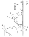
- FIG. 1a shows an embodiment of the invention Load sharing system 1 according to the invention, in which not a separate Ausziehtransport and a separate brake screen, but only one auxiliary screen 7 is shown, both the function of a pull-out screen and a brake screen takes over.
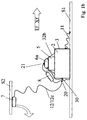
- FIG. 1b is an embodiment of the load-sharing system 1 according to the invention with a first auxiliary screen 7 and another auxiliary screen 8 or its own pull-screen 8, which is therefore provided next to the first auxiliary screen 6.
- the first auxiliary screen 7 has essentially the function of a Ausziehnes and the second auxiliary screen 8 essentially the function of a braking and stabilizing screen.
- Lastenabsetz system 1 may be provided even more auxiliary screens.
- a helper 7 or 8 or a load shield 6 and a plurality of umbrellas so a Umbrella system include.
- the following is only one screen, so one Auxiliary umbrella 7 or 8 or a load shield 6 spoken, always always a screen system or an arrangement of several screens may be meant. The at each several screens occurring multiple connecting strands can then coupled together the intended attachment points or other locations be.
- the control unit 5 may include an actuator for controlling the paraglider over the Control lines as well as a navigation and guidance system and a Include mission planning system, the mission planning system is a target trajectory determined and passed on to the navigation and guidance system, and wherein the navigation and guidance system sensors to the actual position and functions for Determination of the instantaneous deviation of the paraglider system from the nominal path as well as for the determination of control commands, which via signal lines to the Actuator to minimize the deviation of the paraglider system from the desired flight path be transmitted.
- the load 2 or the load-receiving device 3 can before the discharge with the Structure, e.g. the discharge ramp or a flap or the floor or a Structure part S1 of the loading space R, connected unlocking strand 11 may be provided.
- the Structure e.g. the discharge ramp or a flap or the floor or a Structure part S1 of the loading space R
- the auxiliary screen 7 is optionally on the second auxiliary screen 8 by means of a Ausziehstranges 12 with the load shield 6 in conjunction.
- the Ausziehstrang 12 can be formed in one piece or in several parts.
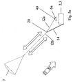
- the load settling system 1 includes a Stabilization harness 14 in the form of at least one stabilizing strand 14, the in Connection with the Ausziehstrang 12 a predetermined position of the load-bearing parachute in ensures the flight phase shown in the figure 5a and 5b.
- FIGs 2a and 2b is in each case an embodiment of the load settling system 1 with two Stabilization strands 14a, 14b provided in the exercise of their Stabilizing function are located below the Ausziehstranges 12 ( Figures 3a, 3b, 4).
- the stabilizer harness 14 is or are the two stabilizer strands 14a, 14b with its first end 15a or 15b to suitable fastening means 16a, 16b at the Last 2 or the load-receiving device 3 and with its second end 18 a, 18 b one or more fasteners or joints 20 and 20a, 20b attached to the Ausziehstrang 12.
- the stabilizing harness can be arranged according to the invention in another way. It is essential that it together with the Ausziehstrang 12 by the air forces the load 2 or the load-receiving device 3 absorbs occurring torques. Since the Ausziehstrang 12 on the packed load umbrella 6a with the control unit. 5 and / or is connected to the load 2 or the load-receiving device 3, hangs the Functionally possible location of the attachment point of the stabilization harness 14 from the place where in flight from the Ausziehstrang 12 on the load 2 or the Lifting device 3 applied traction attacks.
- this point of attack for example, at the bottom of the load 2 or the load-receiving device 3 (about is located at the point 16), it is advantageous to the stabilizing dishes 14 above to connect to this point.
- This example shows that the point of attack of the Ausziehstranges 12 and thus also the position of the packed load shield 6a in the in the figure 4a and 4b illustrated settling phase also seen in the direction of flight XF the front of the load or the load-receiving device 3 may be arranged.
- the load 2 is stabilized via a three-point suspension.
- This can, as shown in the embodiments according to the figures, by means of two Stabilization strands 14a, 14b and a portion 12a of the Ausziehstranges 12th be achieved.
- a stabilizing strand 14 and two branches of Ausziehstranges 12 to accomplish, either directly from one of the auxiliary screens 7, 8 or extend from the one auxiliary screen 7 or from one of these or this branched Ausziehstrang 12 are branched off.
- a strand e.g. a Ausziehstrang or stabilization strand can on various ways according to the prior art, e.g. as a cord or belt, realized be.
- the connection of the stabilizing harness 14 with the Ausziehstrang 12 can via a joint carabiner connection or otherwise done.
- the Junction can be present directly on the Ausziehstrang 12 or at one of the Ausziehstrang 12 branched connector be realized.
- the following will be on a single fastener 18 reference.
- the connection of the Ausziehstranges 12 of the fastener 18 to the load 6 is replaced by a Section 12a, which also in at least one settling phase for stabilization the load participates in a predetermined position.
- the section 12a together with a portion 12b extending from the junction 18 to the auxiliary screen 7 or 8 hinlite be formed in one piece or two parts.
- a junction of the pull-out string 12; 12a, 12b with the connecting member 12d connected, which releasably coupled to the load 2 or the load-receiving device 3 is.
- This connection point can be from the attachment point 18 for the stabilization harness 14 different.
- a trigger device 20 is provided. This can, for example, at the Junction 18 or 18a, 18b or at the connection points 14a, 14b or be arranged between the stabilizer strands.
- the other Ausziehstrang 12c is additionally via a decoupling device 30 and optionally a Connector 12d to the load 2 or the load-receiving device 3 can be coupled and decoupled.
- a decoupling device 30 may be provided with a time delay device work, i. after initiation of the decoupling device 30 is the expiration a predetermined period of time required until the decoupling is actually done. The Time delay function can also be omitted.
- the initiation or activation of the decoupling device 30 is performed by the Solve the decoupling strand 11 preferably by reaching a predetermined tensile force, which occurs when the load 2, the cargo space of the aircraft has left and is pulled away from the air forces by the hull.
- the functional Coupling between the release of the decoupling strand 11 and the initiation or the activation of the decoupling device 30 can be achieved by a mechanical coupling or otherwise.
- the mechanical coupling can by means of a the load 2 or the load-receiving device 3 partially circulating strand be accomplished, the attachment point 11a of the decoupling strand 11th or connects itself to the decoupling device 30.
- the Ausziehstrang 12 would be immediate withdrawn after landing from the aircraft due to air forces and the Stabilizing harnesses 14 are stretched.
- a separation point analogous to the separation point 13 of the three-stage embodiment is not intended.
- the decoupling by means of the decoupling device 30 can alternatively to Actuation due to the achievement of a predetermined tensile force by a different circuit, such as a timer or a signal generator respectively.
- This functional coupling for example, by means of an electrical Circuit or via a transceiver device.
- a Decoupling device 30 is provided, which with the decoupling strand 11th interacts immediately after landing on the aircraft.
- the first triggering device 20 is used to solve the stabilization harness 14 of the load 2 or the load-receiving device 3 or a corresponding one Section of the pull-out line 12 or the severing of the stabilizing strands 14a, 14b of the stabilizing harness 14, respectively at certain times or within certain time intervals.
- the time points or time intervals may be predetermined or manually or automatically during the procedure.
- the first triggering device 20th activated or initiated, and then after a preset time interval the Stabilizing harness 14 to cut or loosen.
- the first triggering device 20 may comprise, for example, an ignition device, is activated by contacts by the occurrence of a predetermined tensile force or voltage in a certain range of Ausziehstranges 12 come into contact. This can be achieved by making the contacts in a prestressed one another be held in a spaced position. The activation causes the ignition of a Fuse. The burning of the fuse is due to a certain Length of the same after a predetermined time of occurrence of the tensile stress, whereupon via an appropriate mechanism, an actuating device for Solution or separation of the stabilizing harness 14 is actuated.
- the predetermined time is depending on the shape and weight of the load 2 in the range between 1 Seconds and 8 seconds and preferably in the range between 2 and 6 seconds after initiation, i. after the first or only auxiliary screen 8 the Pull-out train 12 has set under appropriate train.
- the actuating device may comprise a cutting device, e.g. with a folding knife or another type of device, e.g. B. with a carabiner.
- the initiation of the triggering device 20 may also be via a corresponding sensor and the time delay for the subsequent actuation of the actuation device be realized by means of a timer.
- the triggering device 20 can also by means of a corresponding electrical Means be realized that the tension in the Ausziehstrang 12th For example, a timer the time delay for the subsequent operation actuated the actuating device.
- the further triggering device 21 In the time-delayed activation is the further triggering device 21 preferably at a time interval between 0 and 5 Seconds after the further trigger device 21 activated.
- This time-shifted Activation of the two triggering devices 20, 21 may be functionally dependent or functionally independent of each other.
- an electrical, electronic or mechanical coupling between the two further tripping devices consist.
- each additional trigger device determines 20, 21 the relevant time reference point independently.
- the suspension device or the load harness 70 By releasing the further triggering device 21, the suspension device or the load harness 70 in the carrying and preferably the X-position and brought Distance from the control unit 5 to the load 2 realized.
- the time delay and the actuating device are Components of the prior art usable.
- the time delay can also be realized by means of a fuse wire fuse.
- the actuator can also include a biased pin, which is actuated by a force element and a Cutting device operated.
- the stabilizer harness 14 prevents the load 2 from being in an early phase of the Settling process in vibration device.
- the triggering mechanism 20 effects in one certain phase of the settling process according to the invention, the stabilizing dishes 14 after a predetermined time from the load 2 or the load-receiving device Disconnect 3 and the load or the load-receiving device in a to tilt the given angular range.
- the load shield 6 is in its packed form 6a in the early phase of the Settling process by means of a fastener 32 a attached to the control unit 5.
- the solvability of the fastening means 32a is by means of a second triggering device 40 by triggering or opening a closure or cutting corresponding Strands accomplished.
- the activation or initiation of the second triggering device 40 is preferably carried out as well as the first triggering device 20 by the occurrence of a predetermined tensile force or tension in Ausziehstrang 12.
- the triggering or severing in the time interval between 3 and 12 seconds and preferably between 5 and 8 seconds after the occurrence of the predetermined Tensile stress in the Ausziehstrang 12, and in each case after the release of the Stabilizing harness 14.
- the date of activation of the first 20 - and if any, the other Tripping device 21 - as well as the second triggering device 40 and the Separation of the stabilizing harness 14 and the fastener 18 or 16 may also be determined by the time of departure from the aircraft plus a predetermined time difference, this time difference between 1 and 10 Seconds and preferably between 2 and 5 seconds can be. Especially the time difference can be 3 seconds.
- the Load Shedding System 1 can also be used for an absolute time, the from the navigation and flight guidance calculator or an external, i. an onboard or Ground station or by the mission planning system. In these cases would have the trigger device 20 have a corresponding circuit.
- Both can be in data communication with the navigation and guidance system or the Mission planning system.
- An attachment means 32 can also be used with the load shield and not on the load 2 or hold the load-receiving device 3 fixed control unit 5 at this (Fig. 1b). at Presence of such fixed to the load 2 or the load-receiving device 3 Control unit 5, the attachment means 32a, the packed cargo umbrella 6a also on the control unit 5 or on the load 2 or the load-receiving device 3 hold.
- the load-settling system 1 comprises a first triggering device 20, if any, a further triggering device 21 and a second Tripping device 40, which is in data communication with the navigation and Leadership system or the mission planning system or a timer device can stand.
- a first triggering device 20 By actuating the first triggering device 20 to a predetermined time or due to reaching a predetermined tension in the Ausziehstrang 12 under the action of a time delay function is the Stabilizing harness 14 solved.
- the triggering device 21 solved simultaneously or with a time delay with the triggering device 20.
- the load-suspension system 1 can be a triggering device for releasing the Load shield 6 and the control box 7, which are in data communication with the Navigation and guidance system or the mission planning system and a Timer device, which at a predetermined time by activating the Trigger device releases the attachment of the packed paraglider to the control box, so that the control box 7 is pulled out under the influence of wind steering box strap hangs, and the attachment of the control box on the load-bearing device triggers, so that the load-carrying device to the under load of wind drawn load-carrying straps hangs.
- the triggering device can also be just a fastener both for the control box 7 as well as for the load glide 6 include.
- the times for activating the first 20 and possibly further 21 and the second trigger device for the control box 7 and the time to activate the Tripping device for the load-bearing glider 6 may be identical. In this case as well as in the case where these times are different, the time or can the times for activating the triggering device for the control box 5 and the load parachute 6 can be determined after the settling time of the load settling system 1 from the aircraft plus a predetermined period of time. The time to Actuation of the second trip device 40 may also be determined after Triggering time for the stabilizing dishes 14 plus a predetermined Period of time. In this case, a predetermined period of time can be provided.
- the Triggering times for the triggering devices 20, optionally 21 and 40 of the Navigation and guidance system can be determined, including external sensors, such as e.g. Air data sensors can be used.
- external sensors such as e.g. Air data sensors
- an absolute Time to be used which is determined by an external signal source or the can be hard-coded.
- the load 2 or the load-receiving device 3 hangs at or after the opening of the Load shield 6 by means of a suspension device 60 at the same.
- a control unit 5 depends this means of the suspension device 60 at the Load shield 6, wherein the control unit fixed or rigid with the load 2 and the Lifting device 3 may be connected or this to the control unit. 5 by means of another suspension device 70 depends.
- the suspension device 60 which emanates, for example, from the load shield 6 Strands 61 and 62 may include a dead loop 65 on one of the strands, which can be resolved by means of a third trigger device 90, whereby the Extension of the corresponding strand is effected.
- Loop 65 is shortened to one of the strands 61, 62 as compared to a length of the strands 61, 62 corresponding strand that occurs when the loop is loosened.
- the corresponding shortened strand causes a stronger curvature of the load shield 6 on the side the same, to which the respective strand is connected, whereby a more favorable Falling position is reached.
- the actuation of the triggering device 90 is a predetermined time or a predetermined time interval after the occurrence of a predetermined tension in the corresponding strand, which is a predetermined Time after opening the load screen corresponds. This will accomplish that predetermined time the filling position of the load shield 6 is maintained. After this Actuation of the trigger 90 is achieved by the solution of the loop 65 and the thereby causing extension of the corresponding strand 61, the shape of the Load shield 6 transferred from the filling position in the flying position.
- the third trigger device is optional and can be designed as it is in the Connection with the first triggering device 20 has been described.
- the Loosening of the loop 65 takes place after the actuation of the second triggering device 40 and preferably in the time interval between 8 and 14 seconds after the occurrence of the predetermined tension in the corresponding strand of the suspension device 60 during the opening of the load shield. 6
- the further suspension device 70 may be used in conjunction with a corresponding Sensors and a transmission device of the control unit 5 stand at landing to perform a flare maneuver.
- the additional suspension device 70 can be omitted, when the control unit 5 is fixed on the load 2 or the load-receiving device 3, and the flare actuator system on the relative lifting of the screen from the control unit 5 based.
- the load-sharing system 1 Before settling, the load-sharing system 1 according to the invention is in the Hull or a cargo hold of an aircraft that is open at a particular site is to the load to be dropped or the load-suspension system 1 from the aircraft to remove.
- the auxiliary screen or the first auxiliary screen 7 is in front of the Last 3 thrown off the plane.
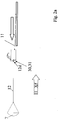
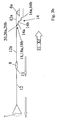
- the phase is prior to the discharge the load 2 from the aircraft and in the figure 2a and 2b, the phase shortly after Absch, in which the load is still on the Entriegelungsstrang 11 with a body part of the Aircraft communicates.
- the auxiliary screen 7 (FIG. 2a) or the first auxiliary screen 7 opens.
- the length of the Ausziehstranges 12 from the auxiliary screen 7 to the decoupling device 30 (Fig. 2a and 2b) and the length of Entriegelungsstranges 11 are such dimensioned that the load in an advantageous and predetermined manner after Leaving the aircraft in the wind turns (Fig. 2a and 2b).
- the decoupling device 30 am Connecting member 12d. This is in the three-stage embodiment of the load-settling system 1 necessarily and in the two-stage embodiment (FIGS. 1a, 2a, 3a) optional and preferably provided.
- the decoupling device 30 by opening the decoupling device 30, the further auxiliary screen 8 or brake screen through the Ausziehstrang 12c away from the load 2 and pulled into the wind, whereby the further auxiliary shield 8 of the Air flow is opened.
- the first Auxiliary umbrella or 7 Auszieh a packing envelope 7b from the auxiliary screen or Stabilizing or braking screen 8 pulls away so that it can unfold.
- the Last 2 is in its spatial position relative to the direction of the Ausziehstranges 12 means Stabilization of the stabilizing harness 14 stabilized.
- the decoupling strand 11 remains due to the opening of the decoupling device 30 preferably on the aircraft.
- another Decoupling mechanism be provided on the aircraft, the opening of which coincide with Opening the decoupling device 30 causes the decoupling strand detached from the aircraft and carried by the load-suspension system 1.
- FIG. 5a and 5b show the load settling system 1 at a slowed by the air resistance speed at which the Ausziehstrang 12 already has an inclination to the horizontal and the load 2 due the dimensions of the stabilizing harness 14 still assumes a horizontal position.
- the triggering device 20 is actuated, for example, at the connection point 18 or 18a, 18b or at the connection points 14a, 14b or in between to the Stabilization strands can be arranged.
- the lengths of the stabilization harness 14 is preferably chosen such that the angle of attack of the load-depositing system 1, So the angle between the course of the extended pull-12 strand Horizontal is between 40 and 60 degrees.
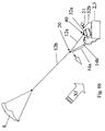
- the load-depositing system 1 is in a second one Flight phase shown after removing the stabilizing lines 14. Removing the Stabilizing lines 14 takes place at a time when the load settling system 1 slowed down by the air resistance. That's why the undressed Ausziehgurt 12 less flat or steeper in the air, as in the in the figure 4a or 4b shown state.
- By removing the stabilizing harness 14 changes the position of the load 2 or the load-bearing device 3 relative to the Ausziehgurt 12.
- an unfavorable, i. too much tilted position the load 2 or the load-receiving device 3 compared to a desired position be avoided.
- the auxiliary or braking screen 8 carries the load 2 preferably via a Three-point suspension by means of the pull-out string 12 and the stabilization harness 14. This is done, as stated above, through the opening of the decoupling device 30. Thereafter pulls the Ausziehstrang 12 at its point of application to the load 2, which in the illustrated embodiments at the top of the load 2 or the Lifting device 3 is located. The thereby at the point of the Pulling chain 12 acting braking force puts the load 2 a torque and brings this to rotate until the stabilizer harness 14 is loaded to train.
- the first triggering device 20, optionally the further triggering device 21, and the second Triggering device 40 initiated or sharpened. This is preferably done by that both triggering devices 20 (optionally with 21) and 40 at the same time, preferably by the occurrence of a predetermined tension in the Extraction string 12 can be activated or initiated and via associated time delay devices actuated with a time delay, wherein first the first triggering device 20, optionally the further triggering device 21 at the same time or with a time delay this, and subsequently the second triggering device 40 is actuated.
- FIGS. 7a and 7b respectively show the phase in which the first triggering device 20 already, the second triggering device 40 is not opened or solved.
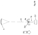
- the opening the second triggering device 40 is shown in Figures 8a and 8b.
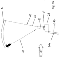
- the result the resulting state is shown in FIGS. 9a and 9b, respectively.
- FIG. 9a is a Embodiment of the load settling system 1 according to the invention shown, in which the Control unit 5 remains at the load 2 until landing.
- This can alternatively also by opening the first triggering device 20th happen.
- This will make a flare at landing by means of appropriate control mechanisms and flare devices in the control unit 5, which are optionally provided are possible.
- the other suspension device 70 may also be different Reasons, z. B. to achieve an advantageous landing, be provided.
- 9b is composed of four suspension strands 71, 72, 73, 74 formed, wherein in each case two suspension strands 71, 72 and 73, 74, the spaced from the control unit 5 or from the load 2 or load-receiving device 3 run between the load 2 and the control unit 5 are connected. At this point are also the two pairs of suspension strands 71,72 and 73, 74 with each other connected. This results in an X position of the suspension strands 71, 72 and 73, 74 achieves the advantage that the stable attitude is independent of the Center of gravity of the load 2 or the pressure point position of the load shield 6. As a result also receives the control unit 5 a stable position.
- the second trip device 40 is actuated (e.g. due to the reaching of the predetermined tension in the Ausziehstrang 12) and the load shield 6 is released so that it can open.
- FIGS. 9a and 11a an embodiment of the load-depositing system 1 is shown, in which the control unit 5 on the load 2 or the load-receiving device. 3 remains docked.
- the control unit 5 can with or without a flare function and - Be equipped.
- FIG 11a an embodiment is shown, in the control unit 5 can accomplish a flare maneuver, which with the Function arrows F1 and F2 is indicated.
- a on the control unit 5 rollably coupled flare hanger strand 61 of Suspension device provided with a trailing edge seen in the direction of flight XF H of the load shield 6 is connected.
- the flare hanger strand 61 rolled up in the control unit 5.
- the flare device therefore comprises a Gravity actuators.
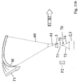
- Such a gravity actuator can also by lowering the load 2 of the Control unit 5 can be achieved, as shown in Figure 11b. It will be the paired suspension strands 71, 72 of the suspension device 70 between the Control unit 5 and the load 2 by the gravity actuator unrolled (movement F2 in the figure 11b), the traction force for the actuation of the Schutex H with a to effect a defined transmission ratio.
- the suspension device 60 also with an opening actuator 65, in particular in the form of a dead loop be provided to improve the opening of the load shield 6.
- the initiation and Actuation also takes place by means of a third triggering device 90, the various types can be designed. This can be done by means of a described mechanism Time delay function to be formed, due to the achievement of a predetermined Tensile stress in one strand of the suspension device 60 is activated or initiated. However, this can also be done via an electrical circuit or a transmitting and receiving device be realized, the externally, i. from outside the load-bearing system 1 can be controlled, or by a control device in the control unit 5.
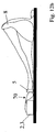
- the landed load settling system 1 is shown in Figures 12a and 12b, respectively.
Landscapes
- Engineering & Computer Science (AREA)
- Aviation & Aerospace Engineering (AREA)
- Air Bags (AREA)
- Ship Loading And Unloading (AREA)
- Tents Or Canopies (AREA)
- Control And Safety Of Cranes (AREA)
- Fluid-Damping Devices (AREA)
- Support Of The Bearing (AREA)
- Emergency Lowering Means (AREA)
Abstract
Description
- dass ein Hilfsschirm aus dem Flugzeug abgesetzt wird,
- dass eine erste Auslöse-Einrichtung betätigt wird, um ein mit dem Ausziehstranges in Verbindung stehendes Stabilisierungs-Geschirr unter dem Einfluss der Luftkräfte in einem gespannten Zustand zu bringen,
- dass eine zweite Auslöse-Einrichtung betätigt wird, um die Entfernung des gepackten Lastenschirms von der Last zu bewirken, so dass die Last an einer Aufhänge-Vorrichtung am Lastenschirm hängt.
- Figur 1a eine schematische Darstellung einer Ausführungsform des erfindungsgemäßen Lastenabsetz-Systems noch in einem Flugzeug, also vor dem Absetzen aus diesem, wobei das dargestellte Lastenabsetz-System einen Hilfsschirm und einen Lastenschirm aufweist,
- Figur 1b eine schematische Darstellung einer weiteren Ausführungsform des erfindungsgemäßen Lastenabsetz-Systems vor dem Absetzen aus dem Flugzeug, wobei das dargestellte Lastenabsetz-System einen ersten Hilfsschirm, einen weiteren Hilfsschirm und einen Lastenschirm aufweist,
- Figur 2a das Lastenabsetz-System nach der Figur 1a kurz nach dem Absetzen aus dem Flugzeug, wobei der Hilfsschirm bereits geöffnet ist und eine Entkopplungs-Einrichtung zur Freigabe des Stabilisierungs-Geschirrs mittels eines Entkopplungs-Stranges noch nicht betätigt ist,
- Figur 2b das Lastenabsetz-System nach der Figur 1b kurz nach dem Absetzen aus dem Flugzeug, wobei der erste Hilfsschirm bereits geöffnet ist und eine Entkopplungs-Einrichtung zur Freigabe des zweiten Hilfsschirmes und des Stabilisierungs-Geschirrs mittels eines Entkopplungs-Stranges noch nicht betätigt ist,
- Figur 3a das Lastenabsetz-System nach der Figur 1a in einer Phase, in der der Hilfsschirm geöffnet ist und die Entkopplungs-Einrichtung zur Freigabe des Stabilisierungs-Geschirrs mittels des Entkopplungs-Stranges betätigt ist,
- Figur 3b das Lastenabsetz-System nach der Figur 1b in einer Phase, in der der erste Hilfsschirm geöffnet ist und die Entkopplungs-Einrichtung zur Freigabe des Stabilisierungs-Geschirrs mittels des Entkopplungs-Stranges betätigt ist, so dass auch der weitere Hilfsschirm von der Last gelöst ist,
- Figur 4 das Lastenabsetz-System nach der Figur 1b in einer auf die Phase nach der Figur 3b folgenden Phase, in der der erste Hilfsschirm aufgrund der Luftkräfte von dem zweiten Hilfsschirm gelöst ist,
- Figur 5a das Lastenabsetz-System nach der Figur 1a in einer Phase, in der der Hilfsschirm geöffnet ist und das Stabilisierungs-Geschirr die Last stabilisiert,
- Figur 5b das Lastenabsetz-System nach der Figur 1b in einer Phase, in der der zweite Hilfsschirm geöffnet ist und das Stabilisierungs-Geschirr die Last stabilisiert,
- Figur 6a das Lastenabsetz-System nach der Figur 1a in einer Phase, in der das Stabilisierungs-Geschirr durch Betätigung einer ersten Auslöse-Einrichtung gelöst ist,
- Figur 6b das Lastenabsetz-System nach der Figur 1b in einer Phase, in der durch Betätigung einer ersten Auslöse-Einrichtung das Stabilisierungs-Geschirr und eine weitere Aufhänge-Vorrichtung gelöst ist, so dass sich die Steuereinheit von der Last entfernt,
- Figur 7a das Lastenabsetz-System nach der Figur 1a in einer weiteren Phase, in der das Stabilisierungs-Geschirr durch Betätigung einer ersten Auslöse-Einrichtung gelöst ist, wobei eine Ausführungsform des Lastenabsetz-Systems gezeigt ist, bei dem die Steuereinheit nach dem Betätigen der ersten Auslöse-Einrichtung an der Last verbleibt,
- Figur 7b das Lastenabsetz-System nach der Figur 1b in einer weiteren Phase, in der das Stabilisierungs-Geschirr durch Betätigung einer ersten Auslöse-Einrichtung gelöst ist, wobei eine Ausführungsform des Lastenabsetz-Systems gezeigt ist, bei dem die Steuereinheit nach dem Betätigen der ersten Auslöse-Einrichtung von der Last mittels einer Last-Aufhängevorrichtung beabstandet ist,
- Figur 8a das Lastenabsetz-System nach der Figur 1a bzw. 7a in einer Ausführungsform, bei dem die Steuereinheit nach dem Betätigen der ersten Auslöse-Einrichtung an der Last verbleibt, und in einer weiteren Phase, in der durch Betätigung einer zweiten Auslöse-Einrichtung der Lastenschirm von der Last freigegeben wird und dabei ist, sich zu öffnen,
- Figur 8b das Lastenabsetz-System nach der Figur 1b bzw. 7b in einer Ausführungsform, bei dem die Steuereinheit nach dem Betätigen der ersten Auslöse-Einrichtung von der Last entfernt an einer Last-Aufhänge-Vorrichtung hängt, und in einer weiteren Phase, in der durch Betätigung einer zweiten Auslöse-Einrichtung der Lastenschirm von der Last freigegeben wird und dabei ist, sich zu Öffnen,
- Figur 9a das Lastenabsetz-System nach der Figur 1a bzw. 7a in einer weiteren Phase, in der durch Betätigung einer zweiten Auslöse-Einrichtung der Lastenschirm geöffnet ist,
- Figur 9b das Lastenabsetz-System nach der Figur 1b bzw. 7b in einer weiteren Phase, in der durch Betätigung einer zweiten Auslöse-Einrichtung der Lastenschirm geöffnet ist, wobei ein Öffnungs-Aktuator in Form einer toten Schlaufe an der Aufhänge-Vorrichtung des Lastenschirms noch nicht betätigt ist, so dass sich der Lastenschirm in einer Öffnungsstellung befindet,
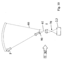
- Figur 10 das Lastenabsetz-System nach der Figur 1b bzw. 7b in einer weiteren Phase, in der der Öffnungs-Aktuator betätigt worden ist, so dass der Lastenschirm von der Füllstellung in die Gleitstellung gebracht worden ist,
- Figur 11a das Lastenabsetz-System nach der Figur 1a bzw. 7a in einer weiteren Phase, in der vor der Landung durch Betätigung einer Aktuatorik unter Ausnutzung der Schirmauftriebskraft mit Schirmanhebung ein Flare durchgeführt wird,
- Figur 11b das Lastenabsetz-System nach der Figur 1b bzw. 7b in einer weiteren Phase, in der vor der Landung durch Betätigung einer Aktuatorik unter Ausnutzung der Gewichtskraft der Last ein Flare durchgeführt wird,
- Figur 12a das Lastenabsetz-System nach der Figur 1a bzw. 7a nach der Landung desselben,
- Figur 12b das Lastenabsetz-System nach der Figur 1b bzw. 7b nach der Landung desselben.
Claims (9)
- Lastenabsetz-System (1) mit einer Last (2) oder einer Lastaufnahme-Vorrichtung (3), mit einem Lastenschirm (6) und mit einem Hilfsschirm (7), der mittels zumindest eines Ausziehstranges (12; 12a, 12b) den Hilfsschirm (7) mit dem Lastengleitschirm (6) verbindet,
dadurch gekennzeichnet,dass ein Stabilisierungs-Geschirr (14; 14a, 14b) zur Verbindung einer Verbindungsstelle (18) des Ausziehstranges (12; 12a, 12b) mit einem Befestigungsmittel (16) an der Last (2) oder der Lastaufnahme-Vorrichtung (3) verbunden ist, um im gespanntem Zustand die Last (2) in einer vorbestimmten Lage relativ zum durch die Luftkräfte ausgezogenen Ausziehstrang (12; 12a, 12b) zu stabilisieren und den Winkel, der durch die vertikale Achse der Last (2) relativ zur Längserstreckung des aufgrund der Luftkräfte nach dem Absetzen ausgezogenen Ausziehstranges (12; 12a, 12b) auftritt, in einem vorbestimmten Winkelbereich zu halten,dass eine erste Auslöse-Einrichtung (20) zur Lösung des Stabilisierungs-Geschirrs (14; 14a, 14b) vorgesehen ist unddass eine zweite Auslöse-Einrichtung (40) zur Freigabe des Lastenschirms (6) von der Last (2) vorgesehen ist, so dass die Last (2) an einer Aufhänge-Vorrichtung (60) am Lastenschirm (6) hängt. - Lastenabsetz-System (1) nach dem Patenanspruch 1, dadurch gekennzeichnet, dass die erste und die zweite Auslöse-Einrichtung durch das Erreichen einer vorbestimmten Zugspannung im Ausziehstrang (12, 12a, 12b) aktiviert und über Zeitverzögerungs-Einrichtungen betätigt wird.
- Lastenabsetz-System (1) nach dem Patenanspruch 1 oder 2, dadurch gekennzeichnet, dass die Zeitverzögerungs-Einrichtung der ersten Auslöse-Einrichtung (20, 21) derart eingestellt ist, dass das Lösen des Stabilisierungs-Geschirrs in einem Zeitintervall zwischen 2 und 6 Sekunden nach dem Auftreten der vorbestimmten Zugspannung in dem Auszieh-Strang (12; 12a, 12b) erfolgt.
- Lastenabsetz-System (1) nach einem der voranstehenden Patenansprüche, dadurch gekennzeichnet, dass die Zeitverzögerungs-Einrichtung der zweiten Auslöse-Einrichtung (40) derart eingestellt ist, dass das Öffnen des Gleitschirmes in einem Zeitintervall zwischen 3 und 12 Sekunden nach dem Auftreten der vorbestimmten Zugspannung in dem Auszieh-Strang (12; 12a, 12b) erfolgt.
- Lastenabsetz-System (1) nach einem der voranstehenden Patenansprüche, dadurch gekennzeichnet, dass eine Entkoppelungs-Einrichtung (30) vorgesehen ist, die mit einem mit einem Flugzeug-Rumpfteil in Verbindung stehenden Entkopplungsstrang (11) zusammenwirkt und eine Stelle (31) des Ausziehstranges (12) lösbar an die Last (2) ankoppelt, so dass das Stabilisierungs-Geschirr (14) in einem entspannten Zustand gehalten wird, wobei durch Lösen des Entkopplungs-Stranges (11) von der Last (2) der Ausziehstrang (12) an seiner Befestigungsstelle freigegeben wird, so dass aufgrund der Luftkräfte das Stabilisierungs-Geschirr (14) zusammen mit dem gesamten Ausziehstrang (12) in einen gespannten Zustand gelangt.
- Lastenabsetz-System (1) nach einem der voranstehenden Patenansprüche, dadurch gekennzeichnet, dass der vorbestimmte Winkel, der durch die vertikale Achse der Last (2) relativ zur Längserstreckung des ausgezogenen Ausziehstranges (12; 12a, 12b) aufgespannt ist, zwischen 40 und 60 Grad liegt.
- Lastenabsetz-System (1) nach einem der voranstehenden Patenansprüche, dadurch gekennzeichnet, dass ein weiterer Hilfsschirm (8) zwischen dem Hilfsschirm (7) und dem Lastenschirm (2) angeordnet ist, wobei der Hilfsschirm (7) über eine Soll-Trennstelle (13) im Ausziehstrang (12) aufgrund der Luftkräfte von dem weiteren Hilfsschirm (8) entkoppelbar ist.
- Lastenabsetz-System (1) nach einem der voranstehenden Patenansprüche, dadurch gekennzeichnet, dass die Steuereinheit (5) lösbar an der Last oder der Lastaufnahme-Vorrichtung und eine weitere Auslöse-Einrichtung (21) zur Freigabe von Befestigungsmitteln (32b) angeordnet sind, um das Lösen der Steuereinheit (5) zu bewirken, wodurch die Last (2) über eine entsprechende Aufhänge-Vorrichtung (70) an der Steuereinheit (5) hängt.
- Verfahren zum Stabilisieren eines aus einem Flugzeug abzusetzenden Lastenabsetz-Systems mit einer Last (2) oder einer Lastaufnahme-Vorrichtung (3), mit einem Lastenschirm (6) und mit einem Hilfsschirm (7), der mittels zumindest eines Ausziehstranges (12; 12a, 12b) den Hilfsschirm (7) mit dem Lastengleitschirm (6) verbindet,
dadurch gekennzeichnet,dass ein Hilfsschirm aus dem Flugzeug abgesetzt wird,dass eine erste Auslöse-Einrichtung (20, 21) betätigt wird, um ein mit dem Ausziehstranges (12) in Verbindung stehendes Stabilisierungs-Geschirr (14) unter dem Einfluss der Luftkräfte in einem gespannten Zustand zu bringen,dass eine zweite Auslöse-Einrichtung (40) betätigt wird, um die Entfernung des gepackten Lastenschirms (6) von der Last (2) zu bewirken, so dass die Last (2) an einer Aufhänge-Vorrichtung (60) am Lastenschirm (6) hängt.
Applications Claiming Priority (6)
| Application Number | Priority Date | Filing Date | Title |
|---|---|---|---|
| DE10219952 | 2002-05-03 | ||
| DE10219952 | 2002-05-03 | ||
| DE10241584 | 2002-09-05 | ||
| DE10241584 | 2002-09-05 | ||
| DE10303788A DE10303788B4 (de) | 2002-05-03 | 2003-01-31 | Lastenabsetz-System mit einem Lastenschirm |
| DE10303788 | 2003-03-31 |
Publications (3)
| Publication Number | Publication Date |
|---|---|
| EP1359091A2 true EP1359091A2 (de) | 2003-11-05 |
| EP1359091A3 EP1359091A3 (de) | 2005-09-28 |
| EP1359091B1 EP1359091B1 (de) | 2007-12-26 |
Family
ID=29219185
Family Applications (1)
| Application Number | Title | Priority Date | Filing Date |
|---|---|---|---|
| EP03008393A Expired - Lifetime EP1359091B1 (de) | 2002-05-03 | 2003-04-11 | Lastenabsetz-System mit einem Lastenschirm |
Country Status (4)
| Country | Link |
|---|---|
| US (1) | US6789766B2 (de) |
| EP (1) | EP1359091B1 (de) |
| AT (1) | ATE382015T1 (de) |
| DE (1) | DE50308875D1 (de) |
Cited By (1)
| Publication number | Priority date | Publication date | Assignee | Title |
|---|---|---|---|---|
| CN117864392A (zh) * | 2023-12-28 | 2024-04-12 | 河北通飞未来飞行器有限公司 | 一种空投系统及其空投方法 |
Families Citing this family (12)
| Publication number | Priority date | Publication date | Assignee | Title |
|---|---|---|---|---|
| US7699268B2 (en) * | 2006-04-10 | 2010-04-20 | Fox Jr Roy L | Sling release mechanism |
| DE102006029147A1 (de) * | 2006-06-24 | 2008-01-03 | Lfk-Lenkflugkörpersysteme Gmbh | Vorrichtung zum Absetzen von unbemannten Flugkörpern aus einem Luftfahrzeug |
| US8083184B2 (en) * | 2008-06-10 | 2011-12-27 | Fox Jr Roy L | Aerial delivery system |
| US8979031B2 (en) | 2008-06-10 | 2015-03-17 | Roy L. Fox, Jr. | Aerial delivery system with munition adapter and latching release |
| US8096509B2 (en) * | 2008-08-07 | 2012-01-17 | Fox Jr Roy L | Parachute inlet control system and method |
| US8033507B2 (en) | 2008-11-05 | 2011-10-11 | Fox Jr Roy L | Parachute release system and method |
| US9845189B2 (en) * | 2010-08-20 | 2017-12-19 | The Skylife Company, Inc. | Methods and systems for mass distribution of supply packs |
| DE102010050896A1 (de) * | 2010-11-10 | 2012-05-10 | Airbus Operations Gmbh | System und Verfahren zum Absetzen von Lasten aus einem Luftfahrzeug |
| US8864080B2 (en) | 2012-01-31 | 2014-10-21 | Roy L Fox, Jr. | Expendable aerial delivery system |
| WO2015149108A1 (en) * | 2014-03-31 | 2015-10-08 | The Commonwealth Of Australia | Aerial deployable rescue package |
| BR112017000923A2 (pt) * | 2014-07-16 | 2018-01-16 | The Skylife Company, Inc. | sistema e método para distribuição em massa de pacotes de abastecimento |
| DE102014018702B4 (de) | 2014-12-18 | 2021-06-24 | Airbus Defence and Space GmbH | Tragesystem zur Durchführung von Abfangmanövern eines Lastengleitschirms und Verfahren zum Verstellen der Hinterkante eines Lastengleitschirms |
Family Cites Families (10)
| Publication number | Priority date | Publication date | Assignee | Title |
|---|---|---|---|---|
| FR1047735A (fr) * | 1951-05-11 | 1953-12-16 | Procédé et dispositifs de parachutage pour charges lourdes, en particulier pour véhicules | |
| US3257089A (en) * | 1964-08-18 | 1966-06-21 | Samms Adolphus | Emergency release for extraction chute |
| US3396924A (en) * | 1966-04-22 | 1968-08-13 | Aerospace Systems Company | Load transfer device |
| GB1281903A (en) * | 1969-10-02 | 1972-07-19 | Hawker Siddeley Aviation Ltd | Improvements in or relating to the dropping of airborne loads |
| US3670999A (en) * | 1970-11-05 | 1972-06-20 | Us Air Force | Parachute force transfer mechanism with built-in open link |
| US3642235A (en) * | 1970-11-23 | 1972-02-15 | Us Army | Extraction force transfer system |
| US3724788A (en) * | 1971-06-03 | 1973-04-03 | Us Air Force | Rapid extraction system |
| US3801051A (en) * | 1973-01-10 | 1974-04-02 | Us Air Force | Tow plate |
| US4342437A (en) * | 1980-10-01 | 1982-08-03 | The United States Of America As Represented By The Secretary Of The Army | High altitude platform air drop system |
| US5816535A (en) * | 1996-04-10 | 1998-10-06 | Lockheed Martin Corporation | Emergency cargo extraction parachute jettison system |
-
2003
- 2003-04-11 EP EP03008393A patent/EP1359091B1/de not_active Expired - Lifetime
- 2003-04-11 DE DE50308875T patent/DE50308875D1/de not_active Expired - Lifetime
- 2003-04-11 AT AT03008393T patent/ATE382015T1/de not_active IP Right Cessation
- 2003-05-05 US US10/429,259 patent/US6789766B2/en not_active Expired - Lifetime
Non-Patent Citations (1)
| Title |
|---|
| None |
Cited By (1)
| Publication number | Priority date | Publication date | Assignee | Title |
|---|---|---|---|---|
| CN117864392A (zh) * | 2023-12-28 | 2024-04-12 | 河北通飞未来飞行器有限公司 | 一种空投系统及其空投方法 |
Also Published As
| Publication number | Publication date |
|---|---|
| US20040000618A1 (en) | 2004-01-01 |
| US6789766B2 (en) | 2004-09-14 |
| DE50308875D1 (de) | 2008-02-07 |
| EP1359091A3 (de) | 2005-09-28 |
| ATE382015T1 (de) | 2008-01-15 |
| EP1359091B1 (de) | 2007-12-26 |
Similar Documents
| Publication | Publication Date | Title |
|---|---|---|
| EP3034406B1 (de) | Tragesystem zur durchführung von abfangmanövern eines lastengleitschirms und verfahren zum verstellen der hinterkante eines lastengleitschirms | |
| DE102005035437B3 (de) | Fluggerät mit einem Rettungslandesystem | |
| DE10007430B4 (de) | Großflächige Fallschirmvorrichtung mit einem Reißnahtstoßdämpfer zur Steuerung des ersten Entfaltens | |
| EP1359091B1 (de) | Lastenabsetz-System mit einem Lastenschirm | |
| DE69631277T2 (de) | Verfahren und Vorrichtung zur Landehilfe eines Flügels | |
| DE19960332C1 (de) | Stellantriebssystem und Verfahren für einen Lastengleitschirm | |
| DE69634113T2 (de) | Verfahren und Vorrichtung für ausklappbare Flügelflächen | |
| DE10241585B4 (de) | Lastengleitfallschirm-System | |
| EP2337740B1 (de) | Flugkörper mit zumindest einem bremsfallschirm sowie befestigungsvorrichtung zur befestigung eines bremsfallschirms an einem flugkörper | |
| DE4336056A1 (de) | Lenkbarer Fallschirm, insbesondere zur Beförderung von Lasten | |
| DE19634017C2 (de) | Gleitschirm-Fluggerät | |
| DE10303788B4 (de) | Lastenabsetz-System mit einem Lastenschirm | |
| DE102017008935B4 (de) | Rettungs-und Bergesystem, Luftfahrzeug mit einem solchen sowie Verfahren zum Betreiben des Rettungs- und Bergesystems | |
| WO2017050333A1 (de) | Trennbare tragfläche für ein luftfahrzeug, luftfahrzeug mit trennbarer tragfläche und verfahren zum landen eines solchen luftfahrzeugs | |
| DE10230535B4 (de) | Vorrichtung zum Absetzen von Lasten aus einem Flugzeug | |
| DE10245944B4 (de) | Stabilisieren von Lasten beim Absetzen aus Transportflugzeugen | |
| DE2841229A1 (de) | Rettungsgeraet fuer flugdrachen und haengegleiter | |
| DE2917900C2 (de) | Öffnungseinrichtung für einen Fallschirm für Hängeleiter | |
| EP3659929A1 (de) | System zur unterstützung eines start- und/oder landevorgangs, luftfahrzeug und verfahren hierzu | |
| DE4244366A1 (de) | Verfahren zum Verlegen eines zwischen weit auseinanderliegenden Auflagern wie Freileitungs- oder Seilbahnmasten laufenden Seils, Kabels o. dgl. | |
| DE3429196A1 (de) | Verfahren zum verlegen eines zwischen weit auseinanderliegenden auflagern wie freileitungs- oder seilbahnmasten laufenden seils, kabels od.dgl. | |
| DE4326416C2 (de) | Aerodynamische Bremssysteme zur Gleitwinkelvergrößerung bei gewichtskraft-gesteuerten Luftfahrzeugen, wie Hängeleitern | |
| DE102004042131A1 (de) | Gleitschirmanordnung für den Gleitschirmsport | |
| EP1066196A1 (de) | Verfahren zum öffnen eines rettungsfallschirms und fallschirmsystem mit einem verfahrensgemäss betätigten fallschirm | |
| DE19522564C2 (de) | Tragvorrichtung für eine am Hubschrauber hängende Last |
Legal Events
| Date | Code | Title | Description |
|---|---|---|---|
| PUAI | Public reference made under article 153(3) epc to a published international application that has entered the european phase |
Free format text: ORIGINAL CODE: 0009012 |
|
| AK | Designated contracting states |
Kind code of ref document: A2 Designated state(s): AT BE BG CH CY CZ DE DK EE ES FI FR GB GR HU IE IT LI LU MC NL PT RO SE SI SK TR |
|
| AX | Request for extension of the european patent |
Extension state: AL LT LV MK |
|
| PUAL | Search report despatched |
Free format text: ORIGINAL CODE: 0009013 |
|
| AK | Designated contracting states |
Kind code of ref document: A3 Designated state(s): AT BE BG CH CY CZ DE DK EE ES FI FR GB GR HU IE IT LI LU MC NL PT RO SE SI SK TR |
|
| AX | Request for extension of the european patent |
Extension state: AL LT LV MK |
|
| RIC1 | Information provided on ipc code assigned before grant |
Ipc: 7B 64D 1/14 B Ipc: 7B 64D 17/74 B Ipc: 7B 64D 1/08 A |
|
| 17P | Request for examination filed |
Effective date: 20051222 |
|
| AKX | Designation fees paid |
Designated state(s): AT BE BG CH CY CZ DE DK EE ES FI FR GB GR HU IE IT LI LU MC NL PT RO SE SI SK TR |
|
| GRAP | Despatch of communication of intention to grant a patent |
Free format text: ORIGINAL CODE: EPIDOSNIGR1 |
|
| GRAS | Grant fee paid |
Free format text: ORIGINAL CODE: EPIDOSNIGR3 |
|
| GRAA | (expected) grant |
Free format text: ORIGINAL CODE: 0009210 |
|
| AK | Designated contracting states |
Kind code of ref document: B1 Designated state(s): AT BE BG CH CY CZ DE DK EE ES FI FR GB GR HU IE IT LI LU MC NL PT RO SE SI SK TR |
|
| REG | Reference to a national code |
Ref country code: GB Ref legal event code: FG4D Free format text: NOT ENGLISH |
|
| REG | Reference to a national code |
Ref country code: IE Ref legal event code: FG4D Free format text: LANGUAGE OF EP DOCUMENT: GERMAN |
|
| REG | Reference to a national code |
Ref country code: CH Ref legal event code: EP |
|
| REF | Corresponds to: |
Ref document number: 50308875 Country of ref document: DE Date of ref document: 20080207 Kind code of ref document: P |
|
| GBT | Gb: translation of ep patent filed (gb section 77(6)(a)/1977) |
Effective date: 20080401 |
|
| PG25 | Lapsed in a contracting state [announced via postgrant information from national office to epo] |
Ref country code: SE Free format text: LAPSE BECAUSE OF FAILURE TO SUBMIT A TRANSLATION OF THE DESCRIPTION OR TO PAY THE FEE WITHIN THE PRESCRIBED TIME-LIMIT Effective date: 20080326 |
|
| PG25 | Lapsed in a contracting state [announced via postgrant information from national office to epo] |
Ref country code: SI Free format text: LAPSE BECAUSE OF FAILURE TO SUBMIT A TRANSLATION OF THE DESCRIPTION OR TO PAY THE FEE WITHIN THE PRESCRIBED TIME-LIMIT Effective date: 20071226 Ref country code: FI Free format text: LAPSE BECAUSE OF FAILURE TO SUBMIT A TRANSLATION OF THE DESCRIPTION OR TO PAY THE FEE WITHIN THE PRESCRIBED TIME-LIMIT Effective date: 20071226 Ref country code: NL Free format text: LAPSE BECAUSE OF FAILURE TO SUBMIT A TRANSLATION OF THE DESCRIPTION OR TO PAY THE FEE WITHIN THE PRESCRIBED TIME-LIMIT Effective date: 20071226 |
|
| NLV1 | Nl: lapsed or annulled due to failure to fulfill the requirements of art. 29p and 29m of the patents act | ||
| PG25 | Lapsed in a contracting state [announced via postgrant information from national office to epo] |
Ref country code: CZ Free format text: LAPSE BECAUSE OF FAILURE TO SUBMIT A TRANSLATION OF THE DESCRIPTION OR TO PAY THE FEE WITHIN THE PRESCRIBED TIME-LIMIT Effective date: 20071226 Ref country code: ES Free format text: LAPSE BECAUSE OF FAILURE TO SUBMIT A TRANSLATION OF THE DESCRIPTION OR TO PAY THE FEE WITHIN THE PRESCRIBED TIME-LIMIT Effective date: 20080406 |
|
| ET | Fr: translation filed | ||
| PG25 | Lapsed in a contracting state [announced via postgrant information from national office to epo] |
Ref country code: SK Free format text: LAPSE BECAUSE OF FAILURE TO SUBMIT A TRANSLATION OF THE DESCRIPTION OR TO PAY THE FEE WITHIN THE PRESCRIBED TIME-LIMIT Effective date: 20071226 Ref country code: RO Free format text: LAPSE BECAUSE OF FAILURE TO SUBMIT A TRANSLATION OF THE DESCRIPTION OR TO PAY THE FEE WITHIN THE PRESCRIBED TIME-LIMIT Effective date: 20071226 |
|
| PG25 | Lapsed in a contracting state [announced via postgrant information from national office to epo] |
Ref country code: PT Free format text: LAPSE BECAUSE OF FAILURE TO SUBMIT A TRANSLATION OF THE DESCRIPTION OR TO PAY THE FEE WITHIN THE PRESCRIBED TIME-LIMIT Effective date: 20080526 |
|
| REG | Reference to a national code |
Ref country code: IE Ref legal event code: FD4D |
|
| BERE | Be: lapsed |
Owner name: EADS DEUTSCHLAND G.M.B.H. Effective date: 20080430 |
|
| PG25 | Lapsed in a contracting state [announced via postgrant information from national office to epo] |
Ref country code: IE Free format text: LAPSE BECAUSE OF FAILURE TO SUBMIT A TRANSLATION OF THE DESCRIPTION OR TO PAY THE FEE WITHIN THE PRESCRIBED TIME-LIMIT Effective date: 20071226 Ref country code: DK Free format text: LAPSE BECAUSE OF FAILURE TO SUBMIT A TRANSLATION OF THE DESCRIPTION OR TO PAY THE FEE WITHIN THE PRESCRIBED TIME-LIMIT Effective date: 20071226 |
|
| PLBE | No opposition filed within time limit |
Free format text: ORIGINAL CODE: 0009261 |
|
| STAA | Information on the status of an ep patent application or granted ep patent |
Free format text: STATUS: NO OPPOSITION FILED WITHIN TIME LIMIT |
|
| PG25 | Lapsed in a contracting state [announced via postgrant information from national office to epo] |
Ref country code: MC Free format text: LAPSE BECAUSE OF NON-PAYMENT OF DUE FEES Effective date: 20080430 |
|
| REG | Reference to a national code |
Ref country code: CH Ref legal event code: PL |
|
| 26N | No opposition filed |
Effective date: 20080929 |
|
| PG25 | Lapsed in a contracting state [announced via postgrant information from national office to epo] |
Ref country code: EE Free format text: LAPSE BECAUSE OF FAILURE TO SUBMIT A TRANSLATION OF THE DESCRIPTION OR TO PAY THE FEE WITHIN THE PRESCRIBED TIME-LIMIT Effective date: 20071226 Ref country code: GR Free format text: LAPSE BECAUSE OF FAILURE TO SUBMIT A TRANSLATION OF THE DESCRIPTION OR TO PAY THE FEE WITHIN THE PRESCRIBED TIME-LIMIT Effective date: 20080327 Ref country code: LI Free format text: LAPSE BECAUSE OF NON-PAYMENT OF DUE FEES Effective date: 20080430 Ref country code: CH Free format text: LAPSE BECAUSE OF NON-PAYMENT OF DUE FEES Effective date: 20080430 |
|
| PG25 | Lapsed in a contracting state [announced via postgrant information from national office to epo] |
Ref country code: BE Free format text: LAPSE BECAUSE OF NON-PAYMENT OF DUE FEES Effective date: 20080430 |
|
| PG25 | Lapsed in a contracting state [announced via postgrant information from national office to epo] |
Ref country code: BG Free format text: LAPSE BECAUSE OF FAILURE TO SUBMIT A TRANSLATION OF THE DESCRIPTION OR TO PAY THE FEE WITHIN THE PRESCRIBED TIME-LIMIT Effective date: 20080326 |
|
| PG25 | Lapsed in a contracting state [announced via postgrant information from national office to epo] |
Ref country code: CY Free format text: LAPSE BECAUSE OF FAILURE TO SUBMIT A TRANSLATION OF THE DESCRIPTION OR TO PAY THE FEE WITHIN THE PRESCRIBED TIME-LIMIT Effective date: 20071226 |
|
| PG25 | Lapsed in a contracting state [announced via postgrant information from national office to epo] |
Ref country code: AT Free format text: LAPSE BECAUSE OF NON-PAYMENT OF DUE FEES Effective date: 20080411 |
|
| PG25 | Lapsed in a contracting state [announced via postgrant information from national office to epo] |
Ref country code: HU Free format text: LAPSE BECAUSE OF FAILURE TO SUBMIT A TRANSLATION OF THE DESCRIPTION OR TO PAY THE FEE WITHIN THE PRESCRIBED TIME-LIMIT Effective date: 20080627 Ref country code: LU Free format text: LAPSE BECAUSE OF NON-PAYMENT OF DUE FEES Effective date: 20080411 |
|
| PG25 | Lapsed in a contracting state [announced via postgrant information from national office to epo] |
Ref country code: TR Free format text: LAPSE BECAUSE OF FAILURE TO SUBMIT A TRANSLATION OF THE DESCRIPTION OR TO PAY THE FEE WITHIN THE PRESCRIBED TIME-LIMIT Effective date: 20071226 |
|
| REG | Reference to a national code |
Ref country code: DE Ref legal event code: R081 Ref document number: 50308875 Country of ref document: DE Owner name: AIRBUS DEFENCE AND SPACE GMBH, DE Free format text: FORMER OWNER: EADS DEUTSCHLAND GMBH, 85521 OTTOBRUNN, DE Effective date: 20140819 |
|
| REG | Reference to a national code |
Ref country code: FR Ref legal event code: PLFP Year of fee payment: 14 |
|
| REG | Reference to a national code |
Ref country code: FR Ref legal event code: PLFP Year of fee payment: 15 |
|
| REG | Reference to a national code |
Ref country code: FR Ref legal event code: PLFP Year of fee payment: 16 |
|
| REG | Reference to a national code |
Ref country code: FR Ref legal event code: CA Effective date: 20180605 Ref country code: FR Ref legal event code: CD Owner name: EADS DEUTSCHLAND GMBH, DE Effective date: 20180605 |
|
| PGFP | Annual fee paid to national office [announced via postgrant information from national office to epo] |
Ref country code: DE Payment date: 20220420 Year of fee payment: 20 Ref country code: IT Payment date: 20220420 Year of fee payment: 20 Ref country code: GB Payment date: 20220420 Year of fee payment: 20 Ref country code: FR Payment date: 20220420 Year of fee payment: 20 |
|
| REG | Reference to a national code |
Ref country code: DE Ref legal event code: R071 Ref document number: 50308875 Country of ref document: DE |
|
| REG | Reference to a national code |
Ref country code: GB Ref legal event code: PE20 Expiry date: 20230410 |
|
| PG25 | Lapsed in a contracting state [announced via postgrant information from national office to epo] |
Ref country code: GB Free format text: LAPSE BECAUSE OF EXPIRATION OF PROTECTION Effective date: 20230410 |