EP1358022B1 - Keilverriegelbare abnehmbare stanz- und matrizenbuchse in haltevorrichtung - Google Patents
Keilverriegelbare abnehmbare stanz- und matrizenbuchse in haltevorrichtung Download PDFInfo
- Publication number
- EP1358022B1 EP1358022B1 EP20020703204 EP02703204A EP1358022B1 EP 1358022 B1 EP1358022 B1 EP 1358022B1 EP 20020703204 EP20020703204 EP 20020703204 EP 02703204 A EP02703204 A EP 02703204A EP 1358022 B1 EP1358022 B1 EP 1358022B1
- Authority
- EP
- European Patent Office
- Prior art keywords
- wedge
- tool
- cavity
- punch
- vertical
- Prior art date
- Legal status (The legal status is an assumption and is not a legal conclusion. Google has not performed a legal analysis and makes no representation as to the accuracy of the status listed.)
- Expired - Lifetime
Links
- 238000010276 construction Methods 0.000 claims description 11
- 230000014759 maintenance of location Effects 0.000 claims 1
- 230000001154 acute effect Effects 0.000 abstract description 51
- 238000000034 method Methods 0.000 abstract description 8
- 229910001315 Tool steel Inorganic materials 0.000 abstract description 2
- 238000003754 machining Methods 0.000 description 9
- 238000004080 punching Methods 0.000 description 6
- 230000000295 complement effect Effects 0.000 description 4
- 229910000760 Hardened steel Inorganic materials 0.000 description 3
- 229910000831 Steel Inorganic materials 0.000 description 3
- 239000000463 material Substances 0.000 description 3
- 239000010959 steel Substances 0.000 description 3
- 230000000712 assembly Effects 0.000 description 2
- 238000000429 assembly Methods 0.000 description 2
- 238000005520 cutting process Methods 0.000 description 2
- 230000000694 effects Effects 0.000 description 2
- 230000013011 mating Effects 0.000 description 2
- 239000002184 metal Substances 0.000 description 2
- 241001290610 Abildgaardia Species 0.000 description 1
- 229910000851 Alloy steel Inorganic materials 0.000 description 1
- 229910000975 Carbon steel Inorganic materials 0.000 description 1
- 229910001209 Low-carbon steel Inorganic materials 0.000 description 1
- 229910000639 Spring steel Inorganic materials 0.000 description 1
- 239000011324 bead Substances 0.000 description 1
- 239000010962 carbon steel Substances 0.000 description 1
- 230000006835 compression Effects 0.000 description 1
- 238000007906 compression Methods 0.000 description 1
- 239000012530 fluid Substances 0.000 description 1
- 230000002452 interceptive effect Effects 0.000 description 1
- 238000004519 manufacturing process Methods 0.000 description 1
- 230000002093 peripheral effect Effects 0.000 description 1
- 238000007493 shaping process Methods 0.000 description 1
Images


Classifications
-
- B—PERFORMING OPERATIONS; TRANSPORTING
- B21—MECHANICAL METAL-WORKING WITHOUT ESSENTIALLY REMOVING MATERIAL; PUNCHING METAL
- B21D—WORKING OR PROCESSING OF SHEET METAL OR METAL TUBES, RODS OR PROFILES WITHOUT ESSENTIALLY REMOVING MATERIAL; PUNCHING METAL
- B21D28/00—Shaping by press-cutting; Perforating
- B21D28/24—Perforating, i.e. punching holes
- B21D28/34—Perforating tools; Die holders
-
- Y—GENERAL TAGGING OF NEW TECHNOLOGICAL DEVELOPMENTS; GENERAL TAGGING OF CROSS-SECTIONAL TECHNOLOGIES SPANNING OVER SEVERAL SECTIONS OF THE IPC; TECHNICAL SUBJECTS COVERED BY FORMER USPC CROSS-REFERENCE ART COLLECTIONS [XRACs] AND DIGESTS
- Y10—TECHNICAL SUBJECTS COVERED BY FORMER USPC
- Y10T—TECHNICAL SUBJECTS COVERED BY FORMER US CLASSIFICATION
- Y10T403/00—Joints and connections
- Y10T403/70—Interfitted members
- Y10T403/7062—Clamped members
- Y10T403/7064—Clamped members by wedge or cam
- Y10T403/7066—Clamped members by wedge or cam having actuator
- Y10T403/7067—Threaded actuator
-
- Y—GENERAL TAGGING OF NEW TECHNOLOGICAL DEVELOPMENTS; GENERAL TAGGING OF CROSS-SECTIONAL TECHNOLOGIES SPANNING OVER SEVERAL SECTIONS OF THE IPC; TECHNICAL SUBJECTS COVERED BY FORMER USPC CROSS-REFERENCE ART COLLECTIONS [XRACs] AND DIGESTS
- Y10—TECHNICAL SUBJECTS COVERED BY FORMER USPC
- Y10T—TECHNICAL SUBJECTS COVERED BY FORMER US CLASSIFICATION
- Y10T83/00—Cutting
- Y10T83/929—Tool or tool with support
- Y10T83/9372—Rotatable type
- Y10T83/9387—Punching tool
-
- Y—GENERAL TAGGING OF NEW TECHNOLOGICAL DEVELOPMENTS; GENERAL TAGGING OF CROSS-SECTIONAL TECHNOLOGIES SPANNING OVER SEVERAL SECTIONS OF THE IPC; TECHNICAL SUBJECTS COVERED BY FORMER USPC CROSS-REFERENCE ART COLLECTIONS [XRACs] AND DIGESTS
- Y10—TECHNICAL SUBJECTS COVERED BY FORMER USPC
- Y10T—TECHNICAL SUBJECTS COVERED BY FORMER US CLASSIFICATION
- Y10T83/00—Cutting
- Y10T83/929—Tool or tool with support
- Y10T83/9457—Joint or connection
- Y10T83/9473—For rectilinearly reciprocating tool
- Y10T83/9476—Tool is single element with continuous cutting edge [e.g., punch, etc.]
Definitions
- the present invention relates to a tool construction with a retainer, the construction being used to secure a tool such as a punch, or, a die bushing (or die or die button), or forming tool, removably in a die shoe.
- a tool such as a punch, or, a die bushing (or die or die button), or forming tool, removably in a die shoe.
- Such a device is according to the preamble of claim 1 e.g. known from WO-A 0103860.
- a retainer for a punch secures the punch held within it to a die shoe, usually the upper, of a punch press so that the punch may be moved downwards into a die bushing with precision, over and over again so that stringent specifications of a punched sheet may be maintained.
- the die bushing is held in a retainer (die bushing retainer) and secured to an opposed die shoe of the punch press.
- both the retainers are removably secured to their respective die shoes; and the punch and the die bushing are also removably secured in their respective retainers.
- a commonly used forming punch has a point for making the desired hole in a sheet of stock, and has an upwardly flared conical portion directly above the tip of the point. The flared portion serves to provide desired concavity.
- a punch and a forming tool or forming punch, and a die bushing are together referred to by the term "tool"; and are identified individually when specifically referred to.
- a forming tool if used, would be analogously held.
- the retainer block 10 includes a through-hardened backing plate 12 conforming to the upper surface of the retainer block, both being adapted to be secured to an upper die shoe of a punch press or other machine with a punching or forming function by suitable fastening means such as Allen-head screws (not shown). Since a tool (punch or forming) is generally used in a vertical attitude in a punch or forming press, the description herein refers to upper and lower in relation to such attitude.
- the retainer block 10 is provided with a cylindrical bore or tool socket 14 in which is slidably inserted and removably secured the shank (upper portion) 22 of the punch 20, the lower portion of which is an oval-shaped point 24.
- Block 10 is also provided with a cylindrical bore 15 which is angularly disposed relative to the bore 14 and which extends inwardly and downwardly into the retainer block 10 so as to partially intersect socket 14. The partial intersection occurs because the lower end of the bore 15 is provided with a stepped surface forming ball seat 13.
- a retainer ball 16 is movably disposed in bore 15, and a helical compression spring 18 is snugly held in the bore 15 with one end abutting the backing plate 12 so as to urge the ball 16 outwardly of the intersecting portion of bore 15. Though the ball projects into the socket 14 the ball cannot escape (into the socket 14).
- the retainer block is also provided with a through-passage or release-hole 17 through which a thin rod or drift pin is inserted to push the ball upward and move it out of the ball seat 13 when the punch 20 is to be removed. To replace the ball 16 when it gets distorted or damaged, the retainer block 10 is removed from the backing plate 12 and the spring and ball removed through the top of bore 15.
- the shank 22 is provided with a semi-pocket or ball seat 25 shaped generally like a one-half of a falling tear drop viewed in longitudinal elevation, and which is adapted to receive locking ball 16 to releasably lock the punch 20 in the bore 14.
- the pocket's upper portion 26 appears as a straight section forming a continuation of the bore 15; and the lower portion is provided with a return section 28 which is curved upon a radius greater than the radius of the ball 16 so as to connect the deepest part of the pocket 25 to the surface of the shank.
- the ball 16 When the ball 16 is held in pocket 25 its bottom may be in contact with the ball if the radius of section 28 is substantially greater than that of the ball; or, if the radius of the ball is substantially greater than that of the return section 28, the extreme edges 34, 35 of the pocket 25 will contact the ball.
- the arcuate section of pocket 25B has a radius smaller than that of a ball 16B so that it engages the corner portions 34B, 35B of the pocket in the shank.
- the diameter of the ball accurately adapted to fit in the pocket so as to have the pocket contact the ball at two opposed points 33 inwardly spaced apart from the edges 34, 35 as shown in Fig 2, the distance inward being chosen so as to avoid forcing the extreme edges 34, 35 outwards.
- the distance inward being chosen so as to avoid forcing the extreme edges 34, 35 outwards.
- the contact at 33 is essentially point-contact with the surface of the pocket 25 and not substantially different from the point contact between the ball 16B and shank 22B with the pocket 25B.
- the die bushing may be held as shown in U.S. Patent No. 3,535,967 to Whistler et al.
- the die bushing is accurately positioned in a flexible retainer into which it is press-fitted and is held in the die retainer block by providing one side of the bushing with a flat surface, the flat cooperating with a corresponding flat on an aligning pin disposed transversely within a transversely extending opening in the die retainer.
- European Patent 0 446 536 A1 to Guy Pignon discloses several embodiments of an invention, including an upside-down perspective view of an assembly, illustrated in Fig 19 of a pair of complementary wedges 1 and 2 forming a parallelpiped, and another assembly, in a normal operating position, illustrated in cross-sectional view in Fig 20, of a single wedge 1, each of which assemblies secures a punch C held in a support plate (or retainer block) 6 which in turn, is secured to a support block (or die shoe) 7 through a backing plate 3.
- the screw 5 enters the die shoe 7; in Fig 20 the screw 5 is inserted through the die shoe 7 and threadedly secured in the wedge 1; in Fig 19 the screw 5 is inserted through the retainer block 6 and threadedly secured in the die shoe 7 (shown in Fig 2 of the Pumble reference).
- the movable wedge 1 is directly, threadedly attached to the die shoe and provides a vertical tool-mating surface against which the tool (punch C) is clamped, and in each case, the orientation of the wedge is vertical, that is, in a substantially inverted V-shaped attitude in which the tool-mating surface is vertical and the opposed surface forms a vertically acute angle, downwardly directed away from vertical, the opposed wedge surface being in contact with the correspondingly inclined surface of the retainer block 6.
- active wedging function is provided only during downward operation of the punch, by virtue of the angled wedge surface.
- active wedging function is meant that there is positive mechanical interference, as if functioning as a detent, by virtue of the angled surface impeding movement in the direction in which the forming tool is moving, whether the forming tool is driven through the stock or withdrawn from it (stripped).
- any wedge with a tool-mating surface becomes tightly held in the wedge cavity.
- the wedge To replace a punch, the wedge must be loosened in its cavity.
- access through the die shoe is necessary. The die shoe must be lowered out of the press, the screw 5 removed, and the wedge 1 driven downward with a dowel inserted through the bore of the screw.
- Fig 2 of the '536 reference there is no access through the die shoe and how the wedge may be loosened is not described.
- the screw which secures the wedge in the reatiner block 6 is either threaded into the die shoe 7 or is slidably inserted though it, to directly attach the wedge to the die shoe.
- assembly requires removing the die shoe from the punch press and then refitting the die shoe in the press.
- a typical die shoe which is about 61 cm x 76 cm x 5 cm (24" x 30" x 2" weighs about 200 Kg (440 lb) or more; removal requires use of a fork-lift truck or overhead crane.
- a tapered holding means such as a wedge-shaped block (“wedge”) locks a forming tool such as a punch or a die bushing and locates it accurately in a retainer block secured to a backing plate of a punch press without being directly attached to the upper die shoe; though the wedge is tightly locked in the retainer block during operation, the forming tool may be replaced without access through the upper die shoe or disassembling the retainer block; preferably, biasing means allows the wedge to lock the forming tool to provide an active wedging function.
- a forming tool such as a punch or a die bushing
- It is therefore a general object of this invention to provide a tooling construction comprising in combination, a retainer block, forming tool such as a punch, die bushing, and a wedge means directly attached to the backing plate but not directly attached to the die shoe of a punch press;
- the retainer block has a tool-and-wedge-receiving cavity or passage therein adapted to receive both the punch or die bushing and the wedge means which, in operation, are locked in position relative to each other;
- the wedge means is provided with at least one inclined surface inclined from the vertical, and a tool-contacting, preferably tool-mating surface; and, biasing means to releasably secure the wedge within the retainer block so as to lock and unlock the punch in the tool cavity.
- EDM wire electric discharge machine
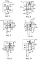
- a punch 20 having a cylindrical shank 22, without a ball-receiving pocket, and a point 24 with a substantially oval cross-section.
- the shank 22 is held in retainer block 30 with wedge 31.
- Wedge 31, in lateral cross-section has a generally polygonal periphery except for one side 32 which is arcuate, representing the wedge's arcuate, essentially vertical tool-mating surface which is adapted to closely receive the shank 22. If the shank 22 were rectangular in cross-section, the side 32 would represent a vertical planar surface and the periphery would be linear.
- the peripheral outline of the mating surfaces is not critical so long as they are in contact to enable the tool to be secured in the retainer block.
- the wedge 31 has an inclined surface 36 which is on the opposite side from the surface 32, and is accurately machined relative to the other surfaces of the cavity; the upper edge of the wedge 31 is represented in phantom outline by the dashed line 14.
- the surface 36 is inclined at a vertically acute angle ⁇ relative to the vertical center line through the punch.
- acute refers to the included angle (as shown) formed by the intersection of the wedge surface and the vertical plane, as viewed frontally in the quadrant identified. Since the arms of this angle open and diverge downwards, the wedging surface is referred to as having a "downwardly acute angle" measured in the lower right quadrant from the lower vertical line, as shown, and the wedge 31 as being substantially "inverted V-shaped".
- the angle ⁇ is not narrowly critical as long as it is less than 90° and greater than 0° (relative to the vertical plane), but it will be evident that a much smaller angle, less than 60° will provide an adequate wedging function.
- the angle is in the range from about 1° to 45°, the larger angles generally facilitating release of the wedge for any reason, for example, when the punch is to be changed.
- the most preferred acute angle is in the range from about 1° to about 20°.
- the wedge 31 is received in the retainer block 30 which is provided with a vertically extending through-passage also referred to as a tool-and-wedge receiving cavity 40 sized to closely receive the upper portion or shank 22 and also the wedge 31 having a tool-mating surface 32.
- a tool-and-wedge receiving cavity 40 sized to closely receive the upper portion or shank 22 and also the wedge 31 having a tool-mating surface 32.
- one wall 41 of the cavity is inclined at the same acute angle as the wedge surface 36 so that the wedge 31 may be moved against and along the wall 41 of the block.
- Wedge 31 is provided with a through-bore 42 into which a fastening means such as an Allen head shoulder screw 43 is inserted, and a snap ring 44 is disposed within a circumferentially extending groove cut above the threads.
- the function of the snap-ring is to retain the wedge in operative relationship with the retaining block and tool, and provide a positive stop against which the wedge's upper surface is biased when the screw 43 is loosened in the backing plate 12 into which the screw 43 is threaded.
- the shank 22 is inserted in the passage between the face 32 and the opposed face of the tool cavity 40.
- the wedge is so dimensioned that tightening the Allen screw 43 tightly secures the shank in the retainer block.
- the Allen screw 43 is loosened and the snap ring 44 will bias the wedge block away from the backing plate 12 sufficiently to free the punch. Without such positive biasing means to urge the wedge downwards, it would be tightly held by the great force exerted during operation of the punch, and could only be removed by disassembling the retainer block 30 from the backing plate 12, then driving the wedge out.
- the wedge-inclined surface Since the purpose of the wedge-inclined surface is to provide an active wedging force it is not necessary that the tool-mating surface be opposite the wedge-inclined surface, though it is preferred that it be. As will be evident in the embodiments shown in Figs 7 and 8 below, neither the die shoe nor the backing plate need be threaded. Of course, in practice, one routinely uses a backing plate for convenience of removal and replacement, and because a die shoe is not adequately hardened.
- the backing plate or punch retainer pad 12 is held in operative position against the upper die shoe of a press by retaining means such as Allen head retaining screws 11 which are inserted in through-bores in the block 10 and threadedly secured in the backing plate 12; dowel pins 19 align the backing plate accurately. It will be appreciated that a through-hardened backing plate is typically provided to save the die shoe (not shown) which is typically not hardened and would be damaged if the retainer pad 12 was omitted.
- a wedge 51 is translated within the tool-and-wedge cavity 50 of a retainer block 52 with a screw, such as an Allen bead set screw 53.
- a screw such as an Allen bead set screw 53.
- One wall 54 of the cavity 50 is inclined at a downwardly acute angle ⁇ , as is one face 55 of the wedge which cooperates with the wall 54 to provide the desired wedging force.
- the upper portion of the wall 54 has a channel-shaped groove cut in it, the length of the channel corresponding to the length of the threads on the set screw 53.
- the upper end of the screw 53 abuts the top of the channel at 57 and the head of the set screw abuts the lower surface of the wedge at 58.
- the inclined wall 54 of the cavity 50 is threaded to threadedly receive the set screw 53, so that as the set screw is rotated in one direction, the wedge is translated upward towards the backing plate 12, and when the direction of rotation of the screw 53 is reversed, the wedge moves downward.
- the extent to which the threads (that is, length measured along the inclined wall) are cut in the wall 54 corresponds to the distance the wedge is to travel.
- tool-mating face 56 of wedge 51 is vertical and arcuate to closely receive the cylindrical shank 22 of the punch 20.
- tool-and-wedge cavity 60 is provided in a retainer block 66 with an inclined wall 64, and wedge 61 has an inclined surface 65 which cooperates with the wall 64, each inclined at an obtuse angle ⁇ relative to acute angle ⁇ .
- obtuse refers to the angle (as shown) formed by the intersection of the wedge surface and the vertical plane, as viewed frontally and measured upward starting at the vertical in the lower right quadrant. This is consistent with the use of the term "acute”. It will be evident that obtuse angle ⁇ is the complementary angle of acute angle ⁇ , but oppositely directed as if in mirror image relationship, the mirror positioned in a plane vertical with respect to the paper.
- the obtuse angle ⁇ of the wedge inclined surface is hereafter referred to as an "upwardly acute angle ⁇ " measured in the upper right quadrant from the upper vertical line, as shown, and the wedge 61 as being substantially "V-shaped".
- this upwardly acute angle is not narrowly critical as long as it is less than 180° and greater than 90° relative to the vertical plane, but it will be evident that an angle greater than 120° will provide an adequate wedging function.
- the angle is in the range from about 135° to 179°, the numerically smaller angles generally facilitating release of the wedge.
- the most preferred obtuse angle is in the range from about 160° to about 179°.
- An upwardly inclined wedge is particularly suited for use with a punch stripper subjected to higher forces than tolerated by a ball lock mechanism.
- Wedge 61 is provided with a bore 62 which is partially threaded so that rotation of an Allen screw 63 threaded in the bore, when the end of the screw is biased against the backing plate 12, translates the wedge up and down.
- shank 22 is closely received in tool-mating surface 67.
- the screw is rotated so the wedge is translated downwards the wedge locks the shank 22 in position; when translated upwards, the shank is released.
- the wedge 61 has an upwardly inclined face, the combination of retainer block and wedge is assembled prior to securing it to the die shoe unless the angle ⁇ is small enough relative to the thickness of the retainer block 66 that, when the wedge 61 is in its uppermost position near the lower surface of the backing plate 12, there is sufficient clearance for the shank to be inserted in the tool-and-wedge cavity 60.
- the screw 63 is threaded in the wedge 61 so that the end of the screw is flush with the surface of the wedge, and this assembly is secured on the backing plate 12. With a typical angle of 3° on the wedge 61, the retainer block 66 is fitted over the wedge so that the cooperating inclined surfaces are in contact and the wedge is captured. The retainer block 66 is then secured to the backing plate 12.
- retainer block 75 is provided with tool-and-wedge cavity 70 having an inclined wall 74, and wedge 71 has an inclined surface 77 which cooperates with the wall 74, each inclined at an upwardly acute angle ⁇ so as to form a substantially V-shaped wedge.
- Wedge 71 is provided with a threaded bore 72 in which a screw 73 is threaded. One portion 73' of the screw 73 is threaded with a left hand thread, and the remaining portion 73" is threaded with a right hand thread. Accordingly, the threaded bore in wedge 71 is of opposite "hand" relative to a threaded bore in backing plate 12, and the screw operates in a manner analogous to a turnbuckle.
- the wedge is captured in the retainer block 75 before it is secured to the die shoe and shank 22 is closely received in tool-mating surface 76.
- the screw is rotated so the wedge is translated downwards the wedge locks the shank 22 in position; when translated upwards, the shank is released.
- retainer block 85 is provided with tool-and wedge cavity 80 having a vertical wall 84, and wedge 81 has a vertical surface 83 which cooperates with the wall 84.
- the tool-mating face 85 of the wedge is inclined at an downwardly acute angle ⁇ and is adapted to closely receive the correspondingly obtusely inclined surface 86 of shank 22 to form a generally inverted V-shaped wedge. Since the shank is cylindrical, the inclined surface 86 is arcuate.
- Wedge 81 is provided with a through-bore 42 into which an Allen screw 43 is inserted and a snap-ring 44 is placed in a groove cut above the threads.
- shank 22 is closely received in tool-mating surface 85; and, the wedge 81 is dimensioned so that tightening the Allen screw 43 secures the shank in the retainer block; loosening the screw allows the snap-ring to help move the wedge and release the punch.
- retainer block 95 is provided with tool-and-wedge cavity 90 having an inclined wall 94, and wedge 91 which has an inclined surface 95 cooperating with wall 94, each inclined at a downwardly acute angle ⁇ .
- the opposed tool-mating face 96 of the wedge is inclined at an upwardly acute angle ⁇ and is adapted to closely receive the correspondingly obtusely inclined surface 97 of shank 22.
- wedge 91 is stated to have a first wedging surface inclined at an upwardly acute angle, and a second wedging surface inclined at a downwardly acute angle to form an inverted V-shaped wedge. Since the shank is cylindrical, the inclined surface 96 is arcuate.
- Wedge 91 is provided with a through-bore 42 into which an Allen screw 43 is inserted and a snap-ring 44 is placed in a groove cut above the threads.
- shank 22 is closely received in tool-mating surface 96; and, the wedge 91 is dimensioned so that tightening the Allen screw 43 secures the shank in the retainer block; loosening the screw 43 in the backing plate 12 allows the snap-ring to help move the wedge and release the punch.
- the shank is shown as being cylindrical, as is conventional, and for the common instance where a the point punches a circular hole in a web of stock, the rotation of the shank in its cavity is immaterial if its clearances relative to the die bushing are correctly established.
- the punched hole is required to be within tolerances less than 25.4 ⁇ m (microns or micrometers) or 0.001" (inch).
- the cylindrical shank is provided with a flat, and a corresponding mating flat is provided in the wedge's tool-mating surface.
- the punch cavity in the retainer block is correspondingly shaped with a minimum clearance, typically 12.7 ⁇ m.
- the force with which the wedge secures the punch in the retainer block is much greater than that exerted by a conventional ball lock and spring in the same application with the same size punches.
- a 9.84 mm (0.25) ball in the pocket of a punch with a 9.5 mm. (0.375”) diam shank and a conventional ball lock and spring is shattered when a stripping force of 272.7 Kg (600 lbs) is exerted on the punch; the same shank is held with a stripping force of 909 Kg (2000 lbs) when it is secured with a downwardly inclined wedge (Fig 6), when slipping of the punch occurred. No such slipping would occur with both an upwardly inclined tool-mating surface and a downwardly inclined wedge-inclined surface (Fig 11).
- FIG 12 there is schematically illustrated a bottom plan view, looking up, of a retainer block 100 in which multiple punches 101, 102, 103, and 104 are commonly held and positioned with dowel pins 19, then secured against a backing plate with Allen screws 11.
- Each punch is a rod of appropriately hardened steel or other metal, the rod having a uniform cross-section, but each rod has a cross-section of different shape.
- Each rod is secured with a wedge having a correspondingly shaped tool-mating surface to receive a portion of the periphery of the punch. The remaining portion of the periphery is received by a correspondingly shaped tool-mating surface in the wall of the retainer, opposite the wedge.
- the tool-mating surface is vertical and the opposed inclined surface is at a downwardly acute angle ⁇ .
- the wedge is vertically translatable in its respective tool cavity to an extent sufficient to release the tool, whether punch, forming tool or die bushing.
- Fig 13 is a perspective view of punch 103 which is of substantially hexagonal cross-section, as shown in the combination of wedge and punch identified by reference numeral 103 in Fig 12. Approximately one-third of the periphery of the punch is received in a one-third-hexagon-shaped tool-mating surface of retainer block 110, and the remaining two-third is received in a vertical surface of corresponding two-third-hexagon shape which is cut in the retainer block.
- Each die bushing is non-circular and has a planar upper surface defining a point-receiving through-passage therein to receive a correspondingly non-circular punch accurately positioned relative to the common die retainer block and the corresponding punches.
- the wedge inclined surface is accurately machined relative to the non-circular point. The goal is to provide aa highly secure and accurate position of the die bushing without having any structural component protruding substantially above the surface of the retainer block 110, that is, does not interfere with accurately positioning stock on the die retainer block.
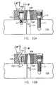
- a die bushing 106 having an elliptical tapered through-bore 109 which at the surface of the retainer block provides the precise desired clearance of the elliptical punch it is to receive.
- One portion of the die bushing 106 is provided with a flat 111 which is held by a corresponding flat surface on wedge 108.
- the tool-and-wedge cavity 112 is outlined by the periphery of the die bushing 106 and the wedge 108, the wall 113 of the cavity being inclined at an acute angle ⁇ to the vertical, this being the included angle between the plane of the inclined surface and the vertical plane through the center of the Allen screw 43, viewed frontally in the upper left hand quadrant.
- the tool-mating surface of the wedge being planar and vertical, as before, an Allen screw 43 threaded into the lower backing plate 12' secures the die bushing in position when the screw is tightened.
- the backing plate 12' is provided with a through-bore 171 to discharge the blank punched out.
- a snap-ring 44 in a groove above the threads allows release of the die bushing when the screw is loosened.
- a spring washer may be interposed between the lower surface of the wedge and the surface of the backing plate.
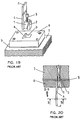
- a wedge 108 directly attached to the lower die shoe 170 of a press.
- the die bushing 106' has an elliptical tapered through-bore 19 which at the surface of the retainer block 110 provides the precise desired clearance of the elliptical punch it is to receive.
- One portion of the die bushing 106 is provided with an inclined surface 111 which is held by a corresponding inclined surface on wedge 108.
- the tool-and-wedge cavity 112 is outlined by the periphery of the die bushing 106' and the wedge 108', the wall 113 of the cavity being inclined at an acute angle ⁇ " measured in the second qudrant from the upper vertical line.
- the wedge 108' has upwardly diverging opposed surfaces; a first wedging surface 151 is inclined at an upwardly and outwardly acute angle ⁇ ', measured in the first quadrant from the upper vertical line; and, an oppositely inclined second wedging surface 152 is inclined upwardly and outwardly at an acute angle ⁇ ", measured in the second quadrant from the upper vertical line, as shown, to form a V-shaped wedge with diverging surfaces.
- retainer block 110 is secured through a lower backing plate 12' to a lower die shoe 170.
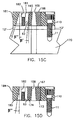
- a die bushing 166 having bore 109 is provided with a vertical surface and an opposed first surface 165 inclined at acute angle ⁇ ', measured in the third quadrant from the lower vertical line is held in the retainer block 110.
- the die bushing 166 is secured in position by wedge 181 having a central stepped bore 182, the lower portion of which is threaded to accept Allen screw 63 which protrudes from the lower surface of the wedge.
- the wedge has a first wedging surface 168 in slidable contact with surface 165 and also inclined at acute angle ⁇ '; and an opposed second wedge surface inclined at acute angle ⁇ ", similarly measured, to form an inverted V-shaped wedge with non-diverging surfaces.
- retainer block is secured through a lower backing plate to a lower die shoe (not shown) as in Fig 15C.
- a die bushing 167 having bore 109 is provided with a opposed first and second vertical surfaces 173 and 174.
- Wedge 184 having partially threaded stepped bore 182 with Allen screw 63 has a vertical first surface in cooperation with surface 174 and an opposed second surface 185 inclined at acute angle ⁇ ", measured in the third quadrant from the lower vertical line, to form an inverted V-shaped wedge with a single diverging surface.
- the cross-section of the wedges illustrated in the Figs 5, 12 & 14 indicate they have been cut from a rectangular block, as would be the wedges cut in Figs 8, 9, 10 and 11, it will be evident, that the wedge could be cut so as to have an arbitrary cross-section (in the lateral plane shown) so long as the tool-mating surface corresponds to the surface of the tool, and the wedge inclined surface corresponds to the inclined surface in the retainer block.
- the conical surface of the partial cone cut in the block corresponds to the conical surface of the conical wedge, the upper outline of which is shown by the dotted line 122.
- the surfaces 123 and 126 of the wedge are vertical and planar.
- the tool-mating surface 124 of the wedge is vertical and arcuate except where it is flatted at 128, corresponding to the flatted cylindrical surface of the shank 22.
- Allen screw 11 and dowel pins 19 secure the retainer block to the die show and an Allen head shoulder bolt 125 with a snap-ring in a groove above the threads, secures the conical wedge to the retainer block 120 so that tightening the conical wedge against the retainer block locks the shank 22 in the block and loosening the screw 125 releases the wedge and allows it to be moved downwards.
- the other wedge 130 in the retainer block 120 is irregularly shaped. It has a planar wedge-inclined-surface the lower edge 131 of which is downwardly inclined at an angle ⁇ , and the upper edge of the surface is indicated by dotted line 131
- Surface 133 is vertical and arcuate, being partially cylindrical, curving outward
- tool-mating surface 135 is vertical, arcuate and partially cylindrical, curving inward
- surface 134 represents the remaining vertical surfaces of the periphery which are shown as a partial polygon. From a practical point of view, one would choose the shape of the wedge which best suits his purpose for the task at hand, using the shape which is most economically cut.
- machining the wedge and retainer block to provide the tool cavity desired is the key to providing the reliability and precision not routinely available in any prior art tool and retainer combination used for a similar purpose.
- the wedge may have plural inclined surfaces, if desired.
- the wedge, punch or die bushing, and retainer block with the appropriate tool cavity may be formed separately by machining them to the desired specifications, a preferred method is forming the tool cavity and wedge essentially simultaneously.
- TW-EDM traveling-wire electrical discharge machine
- a thin continuous wire-like elongate electrode is axially caused to travel or is transported from a supply reel to a wind-up (take-up) reel and a retainer block is disposed in juxtaposition with the traveling-wire electrode while electrical energy in the form of time-spaced electrical pulses is supplied across a machining gap formed between the traveling wire and the block in the presence of a dielectric fluid to effect a series of electrical discharges to remove material from the block.
- the block is displaced relative to the axially transported wire electrode in a prescribed path to produce a desired cutting pattern in the block.
- Conventional machines designed to execute the TV-EDM process are provided with a pair of support arms extending from a column mounted upright on a base of the machine, one of the support arms guiding the continuous wire electrode unwound from the supply reel into the machining region where the workpiece machining portion is located while the other guides the wire electrode having undergone the machining action continuously to the take-up reel.
- the axial transportation of the wire electrode is effected by controlled rotary drive comprising feed and brake roller arrangements which also act to stretch the moving wire guided between the support members under a sufficient tension to allow the wire electrode to travel smoothly and accurately in machining position relative to the workpiece.
- a block of hardened tool steel may be cut precisely, providing of course the machine is programmed appropriately.
- the wedge may be cut from a non-hardened alloy steel which may not need to be hardened, or which may be hardened later.
- the advantage of cutting the wedge from hardened steel is to minimize the distortion which may occur upon hardening.
- a machine which is well-adapted to machine the block as desired is a Mitsubishi FX10 which is preferably operated with a wire having a thickness of about 0.254 mm. (0.010"). Programming instructions for the machine are used conventionally, and being well known to those skilled in the art, need not be described in greater detail herein.
- the length of the tool being greater than the thickness of a retainer block in which it is to be held, it is not economical to cut the tool from the same block of hardened steel as the retainer block and wedge.
- the thickness of the retainer block is typically 2.54 cm (1"). Therefore, the tool, and preferably many tools, the same or different, are cut from a separate block of adequate longer dimension (7.62 cm) than the block from which the wedge and retainer block are cut (2.54 cm).
- retainer block 155 is provided with tool-and-wedge cavity 150 having an inclined wall 154, and wedge 141 which has opposed inclined surfaces 145 and 146, cooperating with wall 154 and the surface 147 of the shank 22, each surface oppositely inclined and directed upwardly at acute angles ⁇ ' and ⁇ " respectively, as shown measured on either side of the upper vertical line, as shown.
- ⁇ ' and ⁇ acute angles
- wedge 141 is stated to have a first wedging surface inclined at an upwardly and outwardly acute angle, and an oppositely inclined second wedging surface inclined at an upwardly and outwardly acute angle, as measured from either side of the upper vertical line, to form a V-shaped wedge with diverging surfaces.
- the tool-mating face 146 of the wedge is inclined at angle ⁇ " and is adapted to closely receive the correspondingly inclined surface 147 of shank 22.
- the choice of angles is not narrowly critical but a relatively small angle ⁇ " in the range from 0.25° to about 10°, preferably 1.5° to 3° is convenient to remove and replace the punch without removing the retainer block 155 from the backing plate 12.
- the angle ⁇ ' is preferably in the range from 3 to 5 times larger than angle ⁇ ", typically in the range from 0.75° to 30°, most preferably from 4.5° to 10°.
- the inclined surface 147 is preferably arcuate; however, the surface 147 may be planar and the wedge surface 146 correspondingly planar.
- Wedge 141 is provided with a stepped through-bore 143 the upper portion of which is threaded and into which an Allen screw 148 is inserted so as to protrude through the upper surface of the wedge and be biased against the lower surface of the backing plate 12.
- the wedge can only be inserted through the upper opening of the cavity 150 before the block 150 is secured to the backing plate.
- the wedge 141 is pushed upward towards the backing plate, enough clearance is provided for the shank 22 of the punch to be inserted and held against wedge surface 146.
- the Allen screw is tightened against the backing plate, the wedge tightly locks the shank in position.
- the Allen screw 148 is backed out, a dowel inserted in the lower portion of the stepped bore 143, and the impact of a hammer drives the wedge up against the backing plate to release the punch.
- the wedge may be removed after removing the punch only if opposed sides of the wedge cavity are not oppositely directed and acutely inclined, as for example shown in Fig 12, where only one side of wedge 105 is inclined.
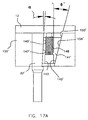
- Fig 17A is a more preferred embodiment of a V-shaped wedge both surfaces of which are angled in the same direction.
- the retainer block 155' is provided with tool-and-wedge cavity 150' having an inclined wall 154', and wedge 141' which has opposed inclined surfaces 145' and 146', cooperating with wall 154' and the surface 147' of the shank 22', each surface inclined in the same direction, and directed upwardly at acute angles ⁇ ' and ⁇ ' respectively, measured on the same side of the upper vertical line, as shown for ⁇ '; for convenience the angle ⁇ ' is shown as the corresponding angle of intersection, measured in the third quadrant, from the lower vertical line.
- wedge 141' is stated to have a first wedging surface inclined at an upwardly and outwardly acute angle, and an oppositely inclined second wedging surface also inclined at an upwardly and outwardly acute angle, both angles measured from the same side of the vertical line in the first quadrant.
- Wedge 141' may also be referred to as having inclined non-diverging surfaces relative to one another.
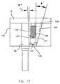
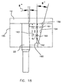
- Fig 18 there is shown an assembly analogous to that shown in Fig 17, with a wedge 161 having the same oppositely inclined opposed surfaces directed upwardly and outwardly at acute angles ⁇ ' and ⁇ ", as shown, except that wedge is provided with a closed bottom spring cavity 160 against the bottom 162 of which is biased a captive biasing means, preferably a helical spring 163, or Z-shaped strip of spring steel, or any compressible member with a spring constant high enough to force the bottom of the wedge downwards and lock the shank 22 of the punch in retainer block 155.
- the wedge 161 is inserted through the upper opening of the cavity 150, and cannot be removed without removing the retainer block 155 from the backing plate 12.
- a dowel is inserted in the lower end of the cavity 150 and driven upwards to overcome the pressure of the spring, releasing the punch.
- the punch is replaced by urging the wedge 161 upwards and inserting the shank of the punch to abut the backing plate 12.
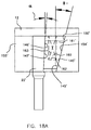
- Fig 18A is a more preferred embodiment of a V-shaped wedge analogous to the wedge shown in Fig 17A, both surfaces of which wedge are angled in the same direction.
- the retainer block 155' is provided with tool-and-wedge cavity 150' having an inclined wall 154', and wedge 161' which has opposed inclined surfaces 145' and 146', cooperating with wall 154' and the surface 147' of the shank 22', each surface inclined in the same direction, and directed upwardly at acute angles ⁇ ' and ⁇ ' respectively, measured on the same side of the upper vertical line, as described for Fig. 17A.
- a laminar plate of mild carbon steel 9.52 mm (0.375") thick is placed above a downwardly relieved (flared) die bushing having an upper diameter of 12.7 mm (0.500”) and a lower diameter of 15.24 mm (0.600”), which clearance between the top and the bottom is conventional and typically 20% of the thickness of the stock being punched.
- the die bushing is a single-angled wedge as shown in Fig 15D.
- a punch 0.500" in diameter is held in the assembly illustrated in Fig 17A and several holes are punched, one after the other, through the plate with a 90-ton C-frame punch press made by Fercute Co. Each hole is 0.500" in diameter; the punched blank, at its upper punch-contacting surface is 14.22 mm (0.500”) and at its lower surface is 0.560" in diameter. In every instance, the punch remained in the retainer block during the stripping motion.
- the same thickness of laminar mild steel plate is placed over a die bushing with a double-angled wedge (as shown in Fig 15C) the die cavity for the punched blank having the same upper and lower diameters, each being 0.500" and providing no conventional clearance.
- the same 0.500" diameter punch used before is then used in the same 90-ton press to punch several holes through the 0.375" thick steel sheet. Each hole is 0.500" in diameter; the punched blank, at its upper punch-contacting surface is 0.500" and at its lower surface is 0.560" in diameter. In every instance the punch was stripped from the steel without being loosened in its retainer block.
Landscapes
- Engineering & Computer Science (AREA)
- Mechanical Engineering (AREA)
- Mounting, Exchange, And Manufacturing Of Dies (AREA)
- Electrical Discharge Machining, Electrochemical Machining, And Combined Machining (AREA)
- Clamps And Clips (AREA)
- Punching Or Piercing (AREA)
- Stored Programmes (AREA)
- Load-Engaging Elements For Cranes (AREA)
- Perforating, Stamping-Out Or Severing By Means Other Than Cutting (AREA)
- Forging (AREA)
- Adornments (AREA)
- Respiratory Apparatuses And Protective Means (AREA)
Claims (7)
- Werkzeugkonstruktion mit:wobei der Werkzeug-Halterungsblock (155') einen Hohlraum (150') zum Aufnehmen eines Werkzeugs definiert, der Hohlraum (150') eine Fläche enthält, die sich in den Werkzeug-Halterungsblock (155') in einer vertikalen Richtung erstreckt, die im wesentlichen rechtwinklig zur Trägerfläche ist, der Hohlraum (150') eine geschlossene, an die Aufspannplatte (12) angrenzende Seite und eine offene, der geschlossenen Seite gegenüberliegende Seite enthält, und die Fläche des Hohlraums (150') eine vertikale Hohlraumwand und eine gegenüberliegende geneigte Hohlraumwand (154') definiert;einer Werkzeug-Trägerstruktur, die eine im wesentlichen ebene Trägerfläche definiert, wobei die Trägerfläche eine ebene Aufspannplattenfläche (12) einer Stanzmaschine enthält;einer Werkzeug-Haltestruktur, die einen Werkzeug-Halterungsblock (155') enthält, der auf der planaren Aufspannplattenfläche der Werkzeug-Trägerstruktur abgestützt ist;
einem Werkzeug (22'), das im Hohlraum (150') angeordnet ist und eine vertikale Werkzeug-Mittellinie definiert, die sich in den Hohlraum (150') von der offenen Seite zur geschlossenen Seite erstreckt, wobei das Werkzeug (22') eine vertikale Werkzeugfläche, die mit der vertikalen Hohlraumwand in Eingriff ist, und eine gegenüberliegende geneigte Werkzeugfläche (147') enthält, die nach außen von der vertikalen Werkzeug-Mittellinie abgewinkelt ist; und
einer Keilstruktur (141', 161'), die eine erste und zweite Keilfläche (145', 146') enthält, die an den gegenüberliegenden Seiten der Keilstruktur (141', 161') angeordnet ist;
dadurch gekennzeichnet, daß die geneigte Hohlraumwand (154'), die der vertikalen Hohlraumwand gegenüberliegt, nach außen von der vertikalen Mittellinie in einer Richtung abgewinkelt ist, die sich von der offenen Seite zur geschlossenen Seite des Hohlraums (150') fortsetzt; und
sowohl die erste als auch die zweite Keilfläche (145', 146') sind nach außen von der vertikalen Mittellinie in einer Richtung weggeneigt, die sich von der offenen Seite zur geschlossenen Seite des Hohlraums (150') fortsetzt, wobei die erste Keilfläche (146') mit der geneigten Werkzeugfläche (147') zusammenwirkt, und die zweite Keilfläche (145') mit der geneigten Hohlraumwand (154') zusammenwirkt. - Werkzeugkonstruktion nach Anspruch 1, die eine Spannvorrichtung (148, 163) enthält, zum Einspannen der Keilstruktur (141', 161') in einer Richtung, die im wesentlichen parallel zur vertikalen Mittellinie weg von der ebenen Aufspannplattenfläche (12) der Werkzeug-Trägerstruktur gerichtet ist, um die Keilstruktur (141', 161') in Eingriff mit dem Werkzeug (22') einzuspannen.
- Werkzeugkonstruktion nach Anspruch 2, wobei sich die Spannvorrichtung (163, 148) durch die Keilstruktur (141', 161') erstreckt und sich von der Keilstruktur (141', 161') in Druckkontakt mit einer Fläche an der geschlossenen Seite des Hohlraums (150') erstreckt.
- Werkzeugkonstruktion nach Anspruch 3, wobei die Spannvorrichtung (163, 148) ein gewindetes Verbindungselement (148) enthält, das mit der Keilstruktur (141', 161') einziehbar in Eingriff ist und nicht einziehbar die Fläche an der geschlossenen Seite des Hohlraums (150') berührt.
- Werkzeugkonstruktion nach Anspruch 1, wobei die Keilstruktur (141', 161') nicht unmittelbar an die Werkzeug-Trägerstruktur befestigt ist und Befestigungsmittel enthält, die mit der Keilstruktur (141', 161') zum lösbaren Verriegeln des Werkzeugs (22') im Hohlraum (150') zusammenwirken.
- Werkzeugkonstruktion nach Anspruch 1, wobei die erste und die zweite Keilfläche (145', 146') in einem ersten und einem zweiten Winkel (α, ') relativ zur vertikalen Mittellinie sind, wobei sich der erste Winkel (α) vom zweiten Winkel (') unterscheidet.
- Werkzeugkonstruktion nach Anspruch 6, wobei der erste Winkel (α) kleiner als der zweite Winkel (') ist.
Applications Claiming Priority (3)
| Application Number | Priority Date | Filing Date | Title |
|---|---|---|---|
| US777482 | 2001-02-05 | ||
| US09/777,482 US6669399B2 (en) | 1999-07-12 | 2001-02-05 | Wedge-lockable removable punch and die bushing in retainer |
| PCT/US2002/001855 WO2002062501A2 (en) | 2001-02-05 | 2002-01-22 | Wedge-lockable removable punch and die bushing in retainer |
Publications (3)
| Publication Number | Publication Date |
|---|---|
| EP1358022A2 EP1358022A2 (de) | 2003-11-05 |
| EP1358022A4 EP1358022A4 (de) | 2004-05-26 |
| EP1358022B1 true EP1358022B1 (de) | 2005-07-06 |
Family
ID=25110377
Family Applications (1)
| Application Number | Title | Priority Date | Filing Date |
|---|---|---|---|
| EP20020703204 Expired - Lifetime EP1358022B1 (de) | 2001-02-05 | 2002-01-22 | Keilverriegelbare abnehmbare stanz- und matrizenbuchse in haltevorrichtung |
Country Status (12)
| Country | Link |
|---|---|
| US (1) | US6669399B2 (de) |
| EP (1) | EP1358022B1 (de) |
| JP (1) | JP2005503924A (de) |
| CN (1) | CN1281872C (de) |
| AT (1) | ATE299055T1 (de) |
| AU (1) | AU2002236838A1 (de) |
| CA (1) | CA2435833C (de) |
| DE (1) | DE60204941T2 (de) |
| ES (1) | ES2243690T3 (de) |
| MX (1) | MXPA03006912A (de) |
| PT (1) | PT1358022E (de) |
| WO (1) | WO2002062501A2 (de) |
Cited By (2)
| Publication number | Priority date | Publication date | Assignee | Title |
|---|---|---|---|---|
| CN106607506A (zh) * | 2016-12-13 | 2017-05-03 | 苏州和林微纳科技有限公司 | 一种快换冲头机构 |
| US9675976B2 (en) | 2013-09-10 | 2017-06-13 | Vermeer Manufacturing Company | Hammer support for rotary tool |
Families Citing this family (51)
| Publication number | Priority date | Publication date | Assignee | Title |
|---|---|---|---|---|
| US6773360B2 (en) * | 2002-11-08 | 2004-08-10 | Taylor Made Golf Company, Inc. | Golf club head having a removable weight |
| US8235844B2 (en) | 2010-06-01 | 2012-08-07 | Adams Golf Ip, Lp | Hollow golf club head |
| US8900069B2 (en) | 2010-12-28 | 2014-12-02 | Taylor Made Golf Company, Inc. | Fairway wood center of gravity projection |
| US7419441B2 (en) | 2002-11-08 | 2008-09-02 | Taylor Made Golf Company, Inc. | Golf club head weight reinforcement |
| US7407447B2 (en) | 2002-11-08 | 2008-08-05 | Taylor Made Golf Company, Inc. | Movable weights for a golf club head |
| US7186190B1 (en) | 2002-11-08 | 2007-03-06 | Taylor Made Golf Company, Inc. | Golf club head having movable weights |
| US7731603B2 (en) | 2007-09-27 | 2010-06-08 | Taylor Made Golf Company, Inc. | Golf club head |
| US20040182209A1 (en) * | 2003-03-18 | 2004-09-23 | Franco James S. | Cold-headed standoff |
| US6823710B1 (en) * | 2003-05-13 | 2004-11-30 | Gary C. Rassette | Die button extractor |
| US6877353B2 (en) * | 2003-05-13 | 2005-04-12 | Kegar Technologies, Llc | Die button extractor |
| FR2865509B1 (fr) * | 2004-01-23 | 2006-04-28 | Maurice Fallavier | Dispositif polygonal de fixation rapide d'un axe |
| US8801541B2 (en) | 2007-09-27 | 2014-08-12 | Taylor Made Golf Company, Inc. | Golf club |
| US7771291B1 (en) | 2007-10-12 | 2010-08-10 | Taylor Made Golf Company, Inc. | Golf club head with vertical center of gravity adjustment |
| US7204181B2 (en) * | 2004-07-02 | 2007-04-17 | Dayton Progress Corporation | Reversible floating punch retainer for punch change retainer tool |
| US9943734B2 (en) | 2004-11-08 | 2018-04-17 | Taylor Made Golf Company, Inc. | Golf club |
| CN104473962B (zh) | 2005-11-01 | 2018-05-01 | 西奈山医学院 | 使用镓化合物的口部和表面微生物的生长控制 |
| ES2303458B1 (es) * | 2006-12-01 | 2009-03-16 | Jesus Maria Vazquez Ferreira | "portautiles de punzonar". |
| US7753806B2 (en) | 2007-12-31 | 2010-07-13 | Taylor Made Golf Company, Inc. | Golf club |
| US8206244B2 (en) | 2008-01-10 | 2012-06-26 | Adams Golf Ip, Lp | Fairway wood type golf club |
| EP2764933B1 (de) * | 2008-12-10 | 2016-10-05 | TRUMPF Werkzeugmaschinen GmbH + Co. KG | Werkzeugsystem mit auswechselbaren Werkzeugeinsätzen für Stanzmaschinen |
| KR101193886B1 (ko) | 2010-05-28 | 2012-10-26 | 현대제철 주식회사 | 금형 고정용 쐐기 해체 방법 및 장치 |
| US8827831B2 (en) | 2010-06-01 | 2014-09-09 | Taylor Made Golf Company, Inc. | Golf club head having a stress reducing feature |
| US8821312B2 (en) | 2010-06-01 | 2014-09-02 | Taylor Made Golf Company, Inc. | Golf club head having a stress reducing feature with aperture |
| US9089749B2 (en) | 2010-06-01 | 2015-07-28 | Taylor Made Golf Company, Inc. | Golf club head having a shielded stress reducing feature |
| US10639524B2 (en) | 2010-12-28 | 2020-05-05 | Taylor Made Golf Company, Inc. | Golf club head |
| US9707457B2 (en) | 2010-12-28 | 2017-07-18 | Taylor Made Golf Company, Inc. | Golf club |
| US8888607B2 (en) | 2010-12-28 | 2014-11-18 | Taylor Made Golf Company, Inc. | Fairway wood center of gravity projection |
| US9220953B2 (en) | 2010-12-28 | 2015-12-29 | Taylor Made Golf Company, Inc. | Fairway wood center of gravity projection |
| CN102398374B (zh) * | 2011-10-31 | 2014-11-26 | 湖南特力液压有限公司 | 压力机 |
| US10265756B2 (en) | 2012-02-06 | 2019-04-23 | Mate Precision Tooling, Inc. | Punch assembly with steel punch point insert removably secured therein |
| JP6000628B2 (ja) * | 2012-05-07 | 2016-10-05 | 日本発條株式会社 | 金型ツール・ホルダー及びその一対の調整ブロックの製造方法 |
| KR101447277B1 (ko) | 2013-03-06 | 2014-10-08 | 삼천리자전거 주식회사 | 시트클램프 |
| US9861864B2 (en) | 2013-11-27 | 2018-01-09 | Taylor Made Golf Company, Inc. | Golf club |
| US10113572B2 (en) * | 2014-06-17 | 2018-10-30 | Koninklijke Philips N.V. | Device having two parts |
| CN107530851B (zh) * | 2015-06-03 | 2020-07-03 | 克斯美库股份有限公司 | 夹紧装置的夹紧臂的装卸装置 |
| CN105107940A (zh) * | 2015-09-17 | 2015-12-02 | 无锡明豪汽车轻量化技术应用有限公司 | 模具迫紧式冲头固定座 |
| US10195497B1 (en) | 2016-09-13 | 2019-02-05 | Taylor Made Golf Company, Inc | Oversized golf club head and golf club |
| US10653926B2 (en) | 2018-07-23 | 2020-05-19 | Taylor Made Golf Company, Inc. | Golf club heads |
| CN109047448B (zh) * | 2018-08-03 | 2024-01-30 | 东莞致宏精密模具有限公司 | 锂电池行业自动平衡锁模装置 |
| WO2020091824A1 (en) * | 2018-11-02 | 2020-05-07 | Moeller Precision Tool, Llc | Ball-lock punch retainer inserts |
| DE102018131158B3 (de) | 2018-12-06 | 2020-06-10 | Gebr. Eberhard Gmbh & Co. Kg | Element-Wechselsystem; Verfahren zum Wechseln eines Elements eines Werkzeugs |
| CN110479875B (zh) * | 2019-08-26 | 2020-08-04 | 耿明亮 | 适用于汽车大型冲压模具维修专用机床的升降机构 |
| KR102735715B1 (ko) * | 2019-12-04 | 2024-11-29 | 주식회사 엘지에너지솔루션 | 노칭장치 |
| US11759685B2 (en) | 2020-12-28 | 2023-09-19 | Taylor Made Golf Company, Inc. | Golf club heads |
| US11406881B2 (en) | 2020-12-28 | 2022-08-09 | Taylor Made Golf Company, Inc. | Golf club heads |
| JP6896948B1 (ja) * | 2021-02-24 | 2021-06-30 | 株式会社リエール | 太陽光パネル設置システム |
| JP7433691B2 (ja) * | 2021-02-24 | 2024-02-20 | 株式会社リエール | 太陽光パネル設置システム |
| CN116060493A (zh) * | 2021-11-04 | 2023-05-05 | 许润柱 | 一种楔式防松垫片的制作方法 |
| CN116689646A (zh) * | 2023-06-16 | 2023-09-05 | 东风汽车集团股份有限公司 | 一种汽车背门外板的负角整形冲压工艺方法 |
| DE102024107975A1 (de) * | 2024-03-20 | 2025-09-25 | Viega Technology Gmbh & Co. Kg | Adapter zum Anschließen eines Antriebsmittels an einen manuell betätigbaren Absperrhahn und System aus einem solchen Adapter und einem manuell betätigbaren Absperrhahn |
| CN119016665A (zh) * | 2024-10-14 | 2024-11-26 | 无锡易通精密机械股份有限公司 | 一种模具安装结构及环形锻件加工设备 |
Family Cites Families (27)
| Publication number | Priority date | Publication date | Assignee | Title |
|---|---|---|---|---|
| FR446536A (fr) | 1912-07-25 | 1912-12-07 | Paul Galvin | Dispositif protecteur pour appuis de fenetres et de balcons |
| US2662773A (en) | 1951-01-12 | 1953-12-15 | Richard H Parsons | Construction of interchangeable dies, punches, etc. |
| US2996158A (en) * | 1958-01-23 | 1961-08-15 | Walter J Greenleaf | Cutting blade lock |
| US3055463A (en) * | 1960-05-19 | 1962-09-25 | Rheinstahl Gmbh Wanheim | Expandable assemblies |
| US3137193A (en) | 1960-11-04 | 1964-06-16 | Lawrence V Whistler | Punch and die mounting device |
| US3535967A (en) | 1968-04-01 | 1970-10-27 | Lawrence V Whistler Sr | Die retaining devices |
| US3572785A (en) * | 1969-12-22 | 1971-03-30 | Minneapolis Electric Steel Cas | Connecting apparatus for power shovel tooth adapters |
| GB1467584A (en) * | 1974-07-15 | 1977-03-16 | Ringfeder Gmbh | Clamping assembly |
| SE403176B (sv) * | 1976-12-22 | 1978-07-31 | Svenska Kram Ab | Lostagbar fattning kring ror eller solid profil med rektangulert tversnitt |
| US4187035A (en) * | 1979-02-14 | 1980-02-05 | Colburn Edward N | Keeper pin system for shovel teeth |
| US4282665A (en) * | 1980-02-06 | 1981-08-11 | Dresser Industries, Inc. | Excavator tooth assembly |
| FI61077C (fi) * | 1980-11-18 | 1982-05-10 | Konejukka Oy | Friktionsfoerband foer hopsaettning av maskinelement med varandra |
| US4663867A (en) * | 1985-10-02 | 1987-05-12 | Esco Corporation | Locking device for whisler type adapter |
| US4925142A (en) * | 1988-09-29 | 1990-05-15 | Aluma-Form, Inc. | Electrical utility pole davit arm |
| US4979724A (en) * | 1989-09-27 | 1990-12-25 | Wedge-Loc Co., Inc. | Double action expansion wedge for mounting collar |
| CZ565890A3 (en) * | 1989-11-18 | 1997-04-16 | Muellenberg Ralph | Conical clamping set |
| US5078063A (en) * | 1990-12-19 | 1992-01-07 | Ag Communication Systems Corporation | Precision mechanical squeegee holding assembly |
| US5417518A (en) * | 1993-04-14 | 1995-05-23 | Bierwith; Robert | Tooth mounting adaptor for excavation bucket |
| US5134793A (en) * | 1991-08-05 | 1992-08-04 | Bierwith Robert S | Tooth mount for excavating bucket |
| DE59305067D1 (de) | 1992-12-15 | 1997-02-20 | Schaerer Soehne Ag Usm U | Klemmvorrichtung |
| US5551795A (en) * | 1994-09-02 | 1996-09-03 | Engibarov; Eddy | Tool holder support assembly |
| US5536106A (en) * | 1995-02-09 | 1996-07-16 | General Motors Corporation | Connection between a shaft and a hub |
| DE29516622U1 (de) | 1995-10-20 | 1996-01-25 | Trw Occupant Restraint Systems Gmbh, 73551 Alfdorf | Befestigung eines Fahrzeuglenkrades an einer Lenkwelle |
| US5881625A (en) | 1997-03-03 | 1999-03-16 | Aip Inc. | Automatic or programmable change-over ball lock punch retainer apparatus |
| ATE208863T1 (de) * | 1997-04-14 | 2001-11-15 | Sit Spa | Vorrichtung zur verriegelung eines mechanischen elementes an einer welle |
| AUPO842697A0 (en) * | 1997-08-06 | 1997-08-28 | Cutting Edges Replacement Parts Pty Ltd | Connection pin assembly |
| US6182545B1 (en) * | 1999-07-12 | 2001-02-06 | Francis Richard Janek, Jr. | Wedge-lockable removable punch and die bushing in retainer |
-
2001
- 2001-02-05 US US09/777,482 patent/US6669399B2/en not_active Expired - Fee Related
-
2002
- 2002-01-22 CN CNB028045815A patent/CN1281872C/zh not_active Expired - Fee Related
- 2002-01-22 CA CA 2435833 patent/CA2435833C/en not_active Expired - Fee Related
- 2002-01-22 JP JP2002562495A patent/JP2005503924A/ja active Pending
- 2002-01-22 DE DE2002604941 patent/DE60204941T2/de not_active Expired - Fee Related
- 2002-01-22 PT PT02703204T patent/PT1358022E/pt unknown
- 2002-01-22 MX MXPA03006912A patent/MXPA03006912A/es unknown
- 2002-01-22 EP EP20020703204 patent/EP1358022B1/de not_active Expired - Lifetime
- 2002-01-22 AT AT02703204T patent/ATE299055T1/de not_active IP Right Cessation
- 2002-01-22 WO PCT/US2002/001855 patent/WO2002062501A2/en not_active Ceased
- 2002-01-22 ES ES02703204T patent/ES2243690T3/es not_active Expired - Lifetime
- 2002-01-22 AU AU2002236838A patent/AU2002236838A1/en not_active Abandoned
Cited By (2)
| Publication number | Priority date | Publication date | Assignee | Title |
|---|---|---|---|---|
| US9675976B2 (en) | 2013-09-10 | 2017-06-13 | Vermeer Manufacturing Company | Hammer support for rotary tool |
| CN106607506A (zh) * | 2016-12-13 | 2017-05-03 | 苏州和林微纳科技有限公司 | 一种快换冲头机构 |
Also Published As
| Publication number | Publication date |
|---|---|
| EP1358022A2 (de) | 2003-11-05 |
| DE60204941D1 (de) | 2005-08-11 |
| CN1281872C (zh) | 2006-10-25 |
| CA2435833C (en) | 2009-06-30 |
| DE60204941T2 (de) | 2006-01-12 |
| CN1531632A (zh) | 2004-09-22 |
| MXPA03006912A (es) | 2004-10-15 |
| ES2243690T3 (es) | 2005-12-01 |
| PT1358022E (pt) | 2005-10-31 |
| CA2435833A1 (en) | 2002-08-15 |
| JP2005503924A (ja) | 2005-02-10 |
| US20010020410A1 (en) | 2001-09-13 |
| ATE299055T1 (de) | 2005-07-15 |
| WO2002062501A3 (en) | 2003-04-10 |
| US6669399B2 (en) | 2003-12-30 |
| EP1358022A4 (de) | 2004-05-26 |
| WO2002062501B1 (en) | 2003-09-18 |
| WO2002062501A2 (en) | 2002-08-15 |
| AU2002236838A1 (en) | 2002-08-19 |
Similar Documents
| Publication | Publication Date | Title |
|---|---|---|
| EP1358022B1 (de) | Keilverriegelbare abnehmbare stanz- und matrizenbuchse in haltevorrichtung | |
| US6182545B1 (en) | Wedge-lockable removable punch and die bushing in retainer | |
| US5860315A (en) | Device for securing tools | |
| US4854789A (en) | Cutting tool assembly | |
| US9186717B2 (en) | Punch assembly with separate adjustable punch guiding shim block | |
| EP2771142B1 (de) | Werkzeugsystem | |
| CA2140919C (en) | Ball lock punch retainer | |
| US4862782A (en) | Turret punch press tool assembly | |
| US5746549A (en) | Metal cutting tool | |
| US11207726B2 (en) | Die for the manufacturing of elongate bodies | |
| CA1076951A (en) | Retainer for punch and die sets | |
| US5624106A (en) | Gripping device | |
| US3797351A (en) | Mounting system for envelope-die holders | |
| US3640170A (en) | Retainer for punch and die sets | |
| EP0362753B1 (de) | Einspannvorrichtung | |
| US5203652A (en) | Self-aligning tap and die wrench and universal threading tool | |
| CA1095399A (en) | Die holder assembly | |
| EP0406202B1 (de) | Klemmvorrichtung zur Herstellung von Nägeln | |
| EP4417348A1 (de) | Einlippenbohrer mit auswechselbaren führungsleisten | |
| US6394439B1 (en) | Two-sided gripping device | |
| GB2233269A (en) | Improved punch assembly | |
| JPS61249634A (ja) | パンチ保持器 | |
| CA2098235A1 (en) | Tooling for turret punch press | |
| EP1366841A1 (de) | Halter für ein Drehwerkzeug, insbesondere für einen Abstechstahl | |
| CA2136262A1 (en) | Floating punch-holder |
Legal Events
| Date | Code | Title | Description |
|---|---|---|---|
| PUAI | Public reference made under article 153(3) epc to a published international application that has entered the european phase |
Free format text: ORIGINAL CODE: 0009012 |
|
| 17P | Request for examination filed |
Effective date: 20030804 |
|
| AK | Designated contracting states |
Kind code of ref document: A2 Designated state(s): AT BE CH CY DE DK ES FI FR GB GR IE IT LI LU MC NL PT SE TR |
|
| AX | Request for extension of the european patent |
Extension state: AL LT LV MK RO SI |
|
| A4 | Supplementary search report drawn up and despatched |
Effective date: 20040413 |
|
| RIC1 | Information provided on ipc code assigned before grant |
Ipc: 7B 21D 28/34 A |
|
| 17Q | First examination report despatched |
Effective date: 20040806 |
|
| GRAP | Despatch of communication of intention to grant a patent |
Free format text: ORIGINAL CODE: EPIDOSNIGR1 |
|
| GRAS | Grant fee paid |
Free format text: ORIGINAL CODE: EPIDOSNIGR3 |
|
| GRAA | (expected) grant |
Free format text: ORIGINAL CODE: 0009210 |
|
| AK | Designated contracting states |
Kind code of ref document: B1 Designated state(s): AT BE CH CY DE DK ES FI FR GB GR IE IT LI LU MC NL PT SE TR |
|
| PG25 | Lapsed in a contracting state [announced via postgrant information from national office to epo] |
Ref country code: AT Free format text: LAPSE BECAUSE OF FAILURE TO SUBMIT A TRANSLATION OF THE DESCRIPTION OR TO PAY THE FEE WITHIN THE PRESCRIBED TIME-LIMIT Effective date: 20050706 Ref country code: TR Free format text: LAPSE BECAUSE OF FAILURE TO SUBMIT A TRANSLATION OF THE DESCRIPTION OR TO PAY THE FEE WITHIN THE PRESCRIBED TIME-LIMIT Effective date: 20050706 Ref country code: LI Free format text: LAPSE BECAUSE OF FAILURE TO SUBMIT A TRANSLATION OF THE DESCRIPTION OR TO PAY THE FEE WITHIN THE PRESCRIBED TIME-LIMIT Effective date: 20050706 Ref country code: FI Free format text: LAPSE BECAUSE OF FAILURE TO SUBMIT A TRANSLATION OF THE DESCRIPTION OR TO PAY THE FEE WITHIN THE PRESCRIBED TIME-LIMIT Effective date: 20050706 Ref country code: CH Free format text: LAPSE BECAUSE OF FAILURE TO SUBMIT A TRANSLATION OF THE DESCRIPTION OR TO PAY THE FEE WITHIN THE PRESCRIBED TIME-LIMIT Effective date: 20050706 |
|
| REG | Reference to a national code |
Ref country code: GB Ref legal event code: FG4D |
|
| REG | Reference to a national code |
Ref country code: CH Ref legal event code: EP |
|
| REG | Reference to a national code |
Ref country code: SE Ref legal event code: TRGR |
|
| REG | Reference to a national code |
Ref country code: IE Ref legal event code: FG4D |
|
| REF | Corresponds to: |
Ref document number: 60204941 Country of ref document: DE Date of ref document: 20050811 Kind code of ref document: P |
|
| PG25 | Lapsed in a contracting state [announced via postgrant information from national office to epo] |
Ref country code: GR Free format text: LAPSE BECAUSE OF FAILURE TO SUBMIT A TRANSLATION OF THE DESCRIPTION OR TO PAY THE FEE WITHIN THE PRESCRIBED TIME-LIMIT Effective date: 20051006 Ref country code: DK Free format text: LAPSE BECAUSE OF FAILURE TO SUBMIT A TRANSLATION OF THE DESCRIPTION OR TO PAY THE FEE WITHIN THE PRESCRIBED TIME-LIMIT Effective date: 20051006 |
|
| REG | Reference to a national code |
Ref country code: PT Ref legal event code: SC4A Effective date: 20050823 |
|
| REG | Reference to a national code |
Ref country code: ES Ref legal event code: FG2A Ref document number: 2243690 Country of ref document: ES Kind code of ref document: T3 |
|
| REG | Reference to a national code |
Ref country code: CH Ref legal event code: PL |
|
| PGFP | Annual fee paid to national office [announced via postgrant information from national office to epo] |
Ref country code: PT Payment date: 20060118 Year of fee payment: 5 |
|
| PGFP | Annual fee paid to national office [announced via postgrant information from national office to epo] |
Ref country code: DE Payment date: 20060120 Year of fee payment: 5 Ref country code: FR Payment date: 20060120 Year of fee payment: 5 Ref country code: GB Payment date: 20060120 Year of fee payment: 5 |
|
| PG25 | Lapsed in a contracting state [announced via postgrant information from national office to epo] |
Ref country code: IE Free format text: LAPSE BECAUSE OF NON-PAYMENT OF DUE FEES Effective date: 20060123 Ref country code: SE Free format text: LAPSE BECAUSE OF NON-PAYMENT OF DUE FEES Effective date: 20060123 |
|
| PGFP | Annual fee paid to national office [announced via postgrant information from national office to epo] |
Ref country code: ES Payment date: 20060130 Year of fee payment: 5 |
|
| PG25 | Lapsed in a contracting state [announced via postgrant information from national office to epo] |
Ref country code: LU Free format text: LAPSE BECAUSE OF NON-PAYMENT OF DUE FEES Effective date: 20060131 Ref country code: MC Free format text: LAPSE BECAUSE OF NON-PAYMENT OF DUE FEES Effective date: 20060131 Ref country code: BE Free format text: LAPSE BECAUSE OF NON-PAYMENT OF DUE FEES Effective date: 20060131 |
|
| PGFP | Annual fee paid to national office [announced via postgrant information from national office to epo] |
Ref country code: IT Payment date: 20060131 Year of fee payment: 5 |
|
| ET | Fr: translation filed | ||
| PLBE | No opposition filed within time limit |
Free format text: ORIGINAL CODE: 0009261 |
|
| STAA | Information on the status of an ep patent application or granted ep patent |
Free format text: STATUS: NO OPPOSITION FILED WITHIN TIME LIMIT |
|
| 26N | No opposition filed |
Effective date: 20060407 |
|
| PG25 | Lapsed in a contracting state [announced via postgrant information from national office to epo] |
Ref country code: NL Free format text: LAPSE BECAUSE OF NON-PAYMENT OF DUE FEES Effective date: 20060801 |
|
| EUG | Se: european patent has lapsed | ||
| NLV4 | Nl: lapsed or anulled due to non-payment of the annual fee |
Effective date: 20060801 |
|
| REG | Reference to a national code |
Ref country code: IE Ref legal event code: MM4A |
|
| PG25 | Lapsed in a contracting state [announced via postgrant information from national office to epo] |
Ref country code: PT Free format text: LAPSE BECAUSE OF NON-PAYMENT OF DUE FEES Effective date: 20070723 |
|
| PG25 | Lapsed in a contracting state [announced via postgrant information from national office to epo] |
Ref country code: DE Free format text: LAPSE BECAUSE OF NON-PAYMENT OF DUE FEES Effective date: 20070801 |
|
| REG | Reference to a national code |
Ref country code: PT Ref legal event code: MM4A Free format text: LAPSE DUE TO NON-PAYMENT OF FEES Effective date: 20070723 |
|
| GBPC | Gb: european patent ceased through non-payment of renewal fee |
Effective date: 20070122 |
|
| REG | Reference to a national code |
Ref country code: FR Ref legal event code: ST Effective date: 20070930 |
|
| PG25 | Lapsed in a contracting state [announced via postgrant information from national office to epo] |
Ref country code: GB Free format text: LAPSE BECAUSE OF NON-PAYMENT OF DUE FEES Effective date: 20070122 |
|
| BERE | Be: lapsed |
Owner name: *WEDGELOCK SYSTEMS LTD Effective date: 20060131 |
|
| REG | Reference to a national code |
Ref country code: ES Ref legal event code: FD2A Effective date: 20070123 |
|
| PG25 | Lapsed in a contracting state [announced via postgrant information from national office to epo] |
Ref country code: FR Free format text: LAPSE BECAUSE OF NON-PAYMENT OF DUE FEES Effective date: 20070131 |
|
| PG25 | Lapsed in a contracting state [announced via postgrant information from national office to epo] |
Ref country code: ES Free format text: LAPSE BECAUSE OF NON-PAYMENT OF DUE FEES Effective date: 20070123 |
|
| PG25 | Lapsed in a contracting state [announced via postgrant information from national office to epo] |
Ref country code: CY Free format text: LAPSE BECAUSE OF FAILURE TO SUBMIT A TRANSLATION OF THE DESCRIPTION OR TO PAY THE FEE WITHIN THE PRESCRIBED TIME-LIMIT Effective date: 20050706 |
|
| PG25 | Lapsed in a contracting state [announced via postgrant information from national office to epo] |
Ref country code: IT Free format text: LAPSE BECAUSE OF NON-PAYMENT OF DUE FEES Effective date: 20070122 |