EP1357354A2 - Bewegungszustandsbestimmung - Google Patents
Bewegungszustandsbestimmung Download PDFInfo
- Publication number
- EP1357354A2 EP1357354A2 EP03252628A EP03252628A EP1357354A2 EP 1357354 A2 EP1357354 A2 EP 1357354A2 EP 03252628 A EP03252628 A EP 03252628A EP 03252628 A EP03252628 A EP 03252628A EP 1357354 A2 EP1357354 A2 EP 1357354A2
- Authority
- EP
- European Patent Office
- Prior art keywords
- velocity
- section
- information
- vehicle
- movement
- Prior art date
- Legal status (The legal status is an assumption and is not a legal conclusion. Google has not performed a legal analysis and makes no representation as to the accuracy of the status listed.)
- Granted
Links
Images


Classifications
-
- G—PHYSICS
- G01—MEASURING; TESTING
- G01C—MEASURING DISTANCES, LEVELS OR BEARINGS; SURVEYING; NAVIGATION; GYROSCOPIC INSTRUMENTS; PHOTOGRAMMETRY OR VIDEOGRAMMETRY
- G01C21/00—Navigation; Navigational instruments not provided for in groups G01C1/00 - G01C19/00
- G01C21/10—Navigation; Navigational instruments not provided for in groups G01C1/00 - G01C19/00 by using measurements of speed or acceleration
- G01C21/12—Navigation; Navigational instruments not provided for in groups G01C1/00 - G01C19/00 by using measurements of speed or acceleration executed aboard the object being navigated; Dead reckoning
-
- G—PHYSICS
- G01—MEASURING; TESTING
- G01C—MEASURING DISTANCES, LEVELS OR BEARINGS; SURVEYING; NAVIGATION; GYROSCOPIC INSTRUMENTS; PHOTOGRAMMETRY OR VIDEOGRAMMETRY
- G01C22/00—Measuring distance traversed on the ground by vehicles, persons, animals or other moving solid bodies, e.g. using odometers, using pedometers
-
- G—PHYSICS
- G01—MEASURING; TESTING
- G01P—MEASURING LINEAR OR ANGULAR SPEED, ACCELERATION, DECELERATION, OR SHOCK; INDICATING PRESENCE, ABSENCE, OR DIRECTION, OF MOVEMENT
- G01P13/00—Indicating or recording presence, absence, or direction, of movement
-
- G—PHYSICS
- G01—MEASURING; TESTING
- G01P—MEASURING LINEAR OR ANGULAR SPEED, ACCELERATION, DECELERATION, OR SHOCK; INDICATING PRESENCE, ABSENCE, OR DIRECTION, OF MOVEMENT
- G01P3/00—Measuring linear or angular speed; Measuring differences of linear or angular speeds
- G01P3/42—Devices characterised by the use of electric or magnetic means
- G01P3/50—Devices characterised by the use of electric or magnetic means for measuring linear speed
-
- G—PHYSICS
- G01—MEASURING; TESTING
- G01P—MEASURING LINEAR OR ANGULAR SPEED, ACCELERATION, DECELERATION, OR SHOCK; INDICATING PRESENCE, ABSENCE, OR DIRECTION, OF MOVEMENT
- G01P7/00—Measuring speed by integrating acceleration
Definitions
- the present invention relates to a movement condition computing device, which computes movement distance information or movement velocity information on a mobile body even when velocity information on the velocity of the mobile body cannot be acquired during travel of the mobile body, and also relates to a movement condition computing method, a movement condition computing program, a recording medium recording this program, and a navigation device.
- Vehicle-installed navigation devices have been known since prior, and such a device is installed in a vehicle, which is mobile body, for detection of the vehicle's present position and display of the vehicle's present position on a map.
- This vehicle-installed navigation device is equipped with a GPS receiver, a computing device, a map storage device, and a display device.
- the abovementioned computing device generates distance information and traveling direction information on the vehicle based on sensor outputs output from a vehicle velocity sensor and a yaw rate sensor.
- this vehicle-installed navigation device detects a relative movement distance and a relative movement direction of the vehicle at each unit time based on the distance information and traveling direction information.
- the navigation device then computes the present position of the vehicle from position information obtained from the GPS receiver and position information obtained based on the relative movement distance and relative movement direction. Thereafter, the map information stored in the map storage device is read and the computed present position is overlapped onto and displayed along with the map information.
- preventive safety devices have come to be equipped in vehicles.
- Many vehicles are already equipped with an ABS (Anti-lock Brake System), which is a representative form of preventive safety device.
- ABS Anti-lock Brake System
- a vehicle velocity pulse signal which the abovementioned vehicle velocity sensor acquires from a vehicle, may take on various forms, such as that acquired from a speedometer-related part of the vehicle, that acquired from an abovementioned ABS-related part, etc.
- an ABS sensor is mounted to a hub unit used at a wheel of a vehicle and the rotation speed of this wheel is detected. Based on this detected rotation speed, a sensor signal is output to an ECU (Electric Control Unit) of the vehicle. Thereafter, this ECU outputs the input sensor signal as the vehicle velocity pulse signal, etc.
- ECU Electronic Control Unit
- the vehicle velocity sensor which is equipped in the vehicle-installed navigation device, detects this vehicle velocity pulse signal and the abovementioned computing device detects the leading edges or trailing edges of the detected vehicle velocity pulse signal and computes the number of pulses.
- a predetermined distance factor is then used to compute the relative movement distance of the vehicle by the following [Equation 1].
- Relative movement distance Number of vehicle velocity pulses ⁇ Distance factor
- ABS sensor when a vehicle is traveling at low velocity, a state in which the wheel is rotating cannot be distinguished from a state in which the wheel is locked. That is, a sensor signal will not be output from the ABS sensor to an ECU in this case. The ECU thus cannot generate the vehicle velocity pulse signal when the vehicle is traveling at less than or equal to a predetermined velocity.
- the vehicle-installed navigation device also cannot acquire the vehicle velocity pulse signal when the vehicle is traveling at less than or equal to the predetermined velocity. That is, when a vehicle is traveling at less than or equal to the predetermined velocity, the relative movement distance or relative movement velocity of the vehicle cannot be computed.
- a main object of the present invention is to provide a movement condition computing device, which can appropriately compute the relative movement distance or relative movement velocity of a mobile body as well as a movement condition computing method, a movement condition computing program, a recording medium recording this program, and a navigation device.
- This invention's movement condition computing device comprises: a velocity information acquisition section, acquiring velocity information concerning the velocity of a mobile body; a minimum output velocity computing section, computing, when the abovementioned velocity information acquisition section cannot acquire the abovementioned velocity information during movement of the abovementioned mobile body, a minimum output velocity of a point in time at which the abovementioned velocity information acquisition section could acquire the abovementioned velocity information; a state information acquisition section, acquiring state information on at least one of start and stop states of the abovementioned mobile body; and a movement condition computing section, computing at least one of movement distance information and movement velocity information on the abovementioned mobile body based on the minimum output velocity computed by the abovementioned minimum output velocity computing section and the state information acquired by the abovementioned state information acquisition section.
- This invention's movement condition computing device comprises: a velocity information acquisition section, acquiring velocity information concerning the velocity of a mobile body; an acceleration information acquisition section, acquiring acceleration information concerning the acceleration of the abovementioned mobile body; and a movement condition computing section, computing, when the abovementioned velocity information acquisition section cannot acquire the abovementioned velocity information during movement of the abovementioned mobile body, at least one of movement distance information and movement velocity information on the abovementioned mobile body based on the acceleration information acquired by the abovementioned acceleration information acquisition section.
- This invention's movement condition computing method comprises the steps of: acquiring velocity information concerning the velocity of a mobile body; computing, when the abovementioned velocity information cannot be acquired during movement of the abovementioned mobile body, a minimum output velocity of a point in time at which the abovementioned velocity information could be acquired; acquiring state information concerning at least one of start and stop states of the abovementioned mobile body; and computing at least one of movement distance information and movement velocity information on the abovementioned mobile body based on the abovementioned minimum output velocity that has been computed and the abovementioned state information that has been acquired.
- This invention's program is a movement condition computing program, characterized in making a computer execute this invention's movement condition computing method described above.
- This invention's recording medium is a recording medium recording a movement condition computing program characterized in storing this invention's movement condition computing program described above in a manner enabling reading by a computer.
- This invention's navigation device comprises: this invention's movement condition computing device described above; and a present position determination section, determining the present position of a mobile body based on movement distance information and movement velocity information computed by the movement condition computing device.
- Fig. 1 is a block diagram, showing the general arrangement of a navigation device by this invention.
- 1 is a vehicle-installed navigation device, and this navigation device 1 is installed in a vehicle, which is a mobile body, to perform display of the present position of the vehicle, guidance, etc.
- This navigation device 1 is equipped with a GPS receiver 2, a sensor unit 3, a map information storage unit 4, a navigation control unit 5, an operation unit 6, and a notification unit 7.
- the vehicle is equipped with an ABS sensor 8 and an ECU 9, and a vehicle velocity detection circuit 10 of sensor unit 3 to be described later inputs signals from this ABS sensor 8 and ECU 9.
- ABS sensor 8 is used for an ABS, which is a preventive safety device of the vehicle.
- This ABS sensor 8 is mounted to a hub unit used in a wheel of the vehicle, detects the rotation speed of this wheel, and outputs a sensor signal, based on the detected rotation speed, to ECU 9 of the vehicle.
- ECU 9 After inputting the sensor signal from ABS sensor 8, ECU 9 performs waveform modification of the input sensor signal to generate a vehicle velocity pulse signal and outputs this generated vehicle velocity pulse signal to sensor unit 3.
- ABS sensor 8 and ECU 9 generate the vehicle velocity pulse signal, and though ABS sensor 8 is described here, the sensor is not limited thereto. It is sufficient that the sensor be one that detects velocity information on the vehicle and, for example, a sensor installed at a speedometer-related part may be used instead.
- GPS receiver 2 detects absolute position information on the vehicle, expressed as latitude and longitude information, and outputs this vehicle position information to navigation control unit 5.
- Sensor unit 3 detects the displacement that accompanies movement of the vehicle and is equipped with a vehicle velocity detection circuit 10, a gyro 11, and an acceleration sensor 12.
- Vehicle velocity detection circuit 10 detects the vehicle velocity pulse signal output from ECU 9 and outputs the signal to navigation control unit 5.
- Gyro 11 detects the vehicle's azimuth angle, that is, the traveling direction in which the vehicle advances. This gyro 11 converts the detected traveling direction to azimuth angle data as traveling direction information in the form, for example, of pulses, voltage, etc., and outputs the traveling direction information to navigation control unit 5. Though a gyro 11 is employed here, a geomagnetic sensor, which detects the absolute direction, etc., may be employed instead.
- Acceleration sensor 12 detects the acceleration in the vehicle's traveling direction. This acceleration sensor 12 converts the detected acceleration to a sensor output value in the form, for example, of pulses, voltage, etc., and outputs this value to navigation control unit 5.
- Map information storage unit 4 stores map information.
- This map information storage unit 4 is equipped, for example, with a DVD-ROM (Digital Video (or Versatile) Disk - Read Only Memory) drive or a CD-ROM (Compact Disk - Read Only Memory) drive, etc., which respectively reproduces, under the control of navigation control unit 5, the contents of a DVD-ROM disk or a CD-ROM disk in which map information is stored.
- DVD-ROM Digital Video (or Versatile) Disk - Read Only Memory
- CD-ROM Compact Disk - Read Only Memory
- Navigation control unit 5 controls the operation of the entire navigation device 1.
- This navigation control unit 5 comprises a CPU, etc., reads and executes a control program stored in an unillustrated ROM, etc., outputs control signals to the respective components of navigation device 1, and performs input and output of data. Though specific illustration will be omitted, navigation control unit 5 is thus equipped in its interior with a CPU, ROM, RAM, and bus lines that connect these components.
- This navigation control unit 5 is also equipped with a movement distance detection section 13, which is a movement condition computing device, a direction information acquisition section 14, a movement condition recognition section 15, and a present position determination section 16.
- movement distance detection section 13 acquires the vehicle velocity pulse signal detected at vehicle velocity detection circuit 10 and computes the relative movement distance or relative movement velocity of the vehicle. Normally, the relative movement distance is computed by the following [Equation 2] based on the number of vehicle velocity pulses, which in turn is based on the acquired vehicle velocity pulse signal, and a distance per pulse (distance factor value), which is set as a predetermined value.
- Relative movement distance Number of vehicle velocity pulses ⁇ Distance factor value
- the relative movement velocity is calculated by the following [Equation 3], using the pulse width (time) of the vehicle velocity pulse signal and the distance factor value.
- Relative movement velocity Distance factor value / Pulse width
- the computed relative movement distance or relative movement velocity is output to movement condition recognition section 15.
- Direction information acquisition section 14 acquires the azimuth angle data output from gyro 11, computes the relative movement direction of the vehicle, and outputs the computed relative movement direction of the vehicle to movement condition recognition section 15.
- Movement condition recognition section 15 computes the vehicle's relative movement distance and relative movement direction for each unit time based on the relative movement distance or relative movement velocity computed at movement distance detection section 13 and the relative movement direction computed at direction information acquisition section 14 and detects the movement condition of the vehicle based on the accumulation of the relative movement distance and relative movement direction. The detected movement condition of the vehicle is then output to present position determination section 14.
- Present position determination section 16 determines the present position of the vehicle. To be more specific, the vehicle's movement condition detected at movement condition recognition section 15 and the vehicle's position information detected at GPS receiver 2 are acquired. The two of information are compared and collated with the map information stored in map information storage unit 4 and the present position is determined by a map matching process, etc. The determined present position of the vehicle is then displayed on a display 17 of notification unit 7 to be described later.
- Operation unit 6 has various unillustrated operation buttons, for example, for instructing the display of the traveling condition, which is the vehicle's movement condition, and other instructions for operating navigation device 1 as suited. Upon input operation of these operation buttons, operation unit 6 suitably outputs predetermined signals to navigation control unit 5 for setting and inputting various conditions, such as the operation details of navigation device 1.
- This operation unit 6 is not limited to an arrangement for input operations by section of operation buttons but may also be arranged for the setting and inputting of various conditions by input operations by section of a touch panel, voice input operations, etc.,
- Notification unit 7 is controlled by navigation control unit 5 and notifies the present position of the vehicle.
- This notification unit 7 is equipped with display 17 and a speaker 18.
- display 17 displays the map data, stored in map information storage unit 4, in various modes and displays the vehicle's present position in an overlapping manner. Also in addition to the function of displaying the map data in such a manner, display 17 also suitably displays TV image data received by an unillustrated TV receiver, image data stored in an optical disk, magnetic disk, or other recording medium, and read by a drive, etc. To be more specific, a liquid crystal, organic EL (electroluminescence), PDP (Plasma Display Panel), or CRT (Cathode-Ray Tube), etc., is used as the display.
- Speaker 18 outputs various information, such as intersection information based on the vehicle's present position, etc., under the instruction of navigation control unit 5.
- Fig. 2 is a diagram, showing the general arrangement of movement distance detection section 13, which is the movement condition computing device of the first embodiment.
- 13 is the movement distance detection section, and this movement distance detection section 13 computes the relative movement distance or relative movement velocity of the vehicle.
- This movement distance detection section 13 is equipped with a processing unit 19 and a database 20.
- Processing unit 19 inputs data output from the respective components of navigation device 1 and performs predetermined computing processes based on these data.
- Processing unit 19 is equipped with a velocity information acquisition section 21, a state information acquisition section 22, a state judgment section 23, a minimum output velocity computing section 24, and a movement condition computing section 25,
- Velocity information acquisition section 21 acquires the vehicle velocity pulse signal detected at vehicle velocity detection circuit 10 and computes pulse widths (times), which are periods based on the leading edges or trailing edges of the acquired vehicle velocity pulse signal.
- velocity information acquisition section 21 detects the state transitions at the leading edges of the signal and the trailing edges of the signal to acquire the respective transition positions (times) and record them in database 20. Pulse widths are then computed based on transition positions (times) recorded in advance in database 20 and on the acquired transition positions (times).
- velocity information acquisition section 21 computes pulse widths A and pulse widths B as shown in Fig. 3. These computed pulse widths A and pulse widths B are recorded in database 20.
- This velocity information acquisition section 21 also computes the number of vehicle velocity pulses from the vehicle velocity pulse signal that has been acquired within a predetermined period. This velocity information acquisition section 21 then outputs the pulse widths of the acquired vehicle velocity pulse signal and the computed number of vehicle velocity pulses to movement condition computing section 25.
- State information acquisition section 22 inputs the sensor signal output from acceleration sensor 12 and acquires state information concerning start and stop states of the vehicle.
- the acquired state information is output to state judgment section 23.
- the sensor signal from acceleration sensor 12 is input here, the vehicle's state information may be acquired by input of the output signal from gyro 11 instead.
- State judgment section 23 acquires the state information output from state information acquisition section 22 and judges the start and stop states of the vehicle. After this judgment, a signal is output to minimum output velocity computing section 24 and the judged start position (time) and stop position (time) are output to movement condition computing section 25.
- ABS sensor 8 which is the source of generation of this vehicle velocity pulse signal, detects the rotation of a wheel of the vehicle, and when the vehicle is traveling at low speed, the pulse width (time) acquired at velocity information acquisition section 21 will be extremely long. That is, if the vehicle stops or starts during the acquisition of this pulse width, vehicle information acquisition section 21 will acquire the pulse width that includes this stop or start state of the vehicle.
- Movement condition calculation section 25 cannot compute the vehicle's relative movement distance or relative movement velocity with good precision using a pulse width acquired in such a manner or the number of vehicle velocity pulses based on the vehicle velocity pulse signal.
- the acceleration of the vehicle in a state close to the stopping or starting of the vehicle is computed at minimum output velocity computing section 24.
- minimum output velocity computing section 24 computes a minimum output velocity immediately prior to the stopping of the vehicle or after the starting of the vehicle based on the pulse widths A or pulse widths B recorded in database 20. The computed minimum output velocity is output to movement condition computing section 25.
- Movement condition computing section 25 computes the relative movement distance and the relative movement velocity respectively in two processes. To be more specific, in a first process, movement condition computing section 25 acquires the number of vehicle velocity pulses counted at velocity information acquisition section 21. The movement distance of the vehicle per pulse (distance factor value), which is recorded in database 20, is also read. Then based on this number of vehicle velocity pulses and the distance factor value, the relative movement distance of the vehicle is computed by the above-described [Equation 2].
- movement condition computing section 25 acquires the pulse width acquired at velocity information acquisition section 21.
- the movement distance of the vehicle per pulse (distance factor value), which is recorded in database 20, is also read. Then based on this distance factor value and the pulse width, the relative movement velocity of the vehicle is computed by the above-described [Equation 3].
- Such processes are carried out in a period in which the vehicle velocity pulse signal can be acquired by velocity information acquisition section 21.
- movement condition computing section 25 computes the relative movement distance and the relative movement velocity based on the minimum output velocity computed at minimum output velocity computing section 24 and on the period in which the vehicle velocity pulse signal could not be acquired by velocity information acquisition section 21. The details of this computing method shall be described later.
- Database 20 stores data output from processing unit 19 and also stores the distance factor value, which is the vehicle's movement distance per pulse and is set in advance by a user or maker, etc. This distance factor value may also be computed automatically by the navigation device by use of road data, etc., included in the map information.
- This database 20 is equipped with a distance factor value storage section 26 and a velocity information recording section 27.
- Distance factor storage section 26 is arranged, for example, from a rewritable SRAM (Static Random Access Memory), etc., and stores the abovementioned distance factor value.
- SRAM Static Random Access Memory
- Velocity information recording section 27 is arranged, for example, from a rewritable SRAM, etc. This velocity information recording section 27 is equipped with a transition position recording section 28 and a pulse width recording section 29.
- transition position recording section 28 are recorded the respective state transition positions (times) of the leading edges and trailing edges of the vehicle velocity pulse signal acquired by velocity information acquisition section 21.
- pulse width recording section 29 the pulse widths A or pulse widths B, which have been computed by velocity information acquisition section 21 based on the transition positions recorded in transition position recording section 28, are recorded in association with the transition positions (times).
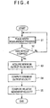
- Fig. 4 is a flowchart, illustrating the movement condition computing method that is implemented by movement distance detection section 13 in the vehicle stopping process.
- Velocity information acquisition section 21 acquires the vehicle velocity pulse signal detected at vehicle velocity detection circuit 10. The vehicle velocity pulse signal that has been input within a predetermined period is counted to compute the number of vehicle velocity pulses. Or the pulse widths of the input vehicle velocity pulse signal are measured (step 1).
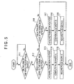
- Fig. 5 is a flowchart, illustrating the method by which the pulse widths of the vehicle velocity pulse signal are measured at velocity information acquisition section 21. This pulse width measurement method shall now be described with reference to Fig. 3 and Fig. 5.
- Velocity information acquisition section 21 acquires the vehicle velocity pulse signal detected at vehicle velocity detection circuit 10 and judges whether or not the logic of this vehicle velocity pulse signal has changed (step S11). More specifically, the state transition of a leading edge or a trailing edge of the vehicle velocity pulse signal waveform is detected as shown in Fig. 3.
- step S11 velocity information acquisition section 21 judges that the logic of the vehicle velocity pulse signal has not changed, a return to start is performed and the measurement of the pulse width is continued.
- step S11 velocity information acquisition section 21 detects that the logic of the vehicle velocity pulse signal has changed. In this case, whether or not a state transition of a leading edge of the signal has been detected is judged (step S12).
- step S12 If in step S12, it is judged that the state transition of a leading edge of the signal has been detected, velocity information acquisition section 21 acquires the position (time) at which this transition occurred (step S13). This transition position is also recorded in transition position recording section 28 of database 20.
- velocity information acquisition section 21 computes pulse width A (Fig. 3) based on the acquired transition position (time) and on a transition position (time) that had been recorded in advance in transition position recording section 28 of database 20 (step S14).
- the pulse width A computed in step S13 is stored in pulse width recording section 29 of database 20 (step S15). By repeating the above processes, the pulse widths A are successively recorded in pulse width recording section 29 of database 20.
- step S12 it is judged that the state transition of a leading edge of the signal has not been detected, it is then judged whether or not the state transition of a trailing edge of the signal has been detected (step S16).
- step S16 If in step S16, it is judged that the state transition of a trailing edge of the signal has been detected, velocity information acquisition section 21 acquires the position (time) at which this transition occurred (step S17). This transition position (time) is also recorded in transition position recording section 28 of database 20.
- Velocity information acquisition section 21 computes pulse width B (Fig. 3) based on the position (time) acquired in step S17 and on a transition position (time) that had been recorded in advance in transition position recording section 28 of database 20 (step S18).
- the pulse width B computed in step S18 is stored in pulse width recording section 29 of database 20 (step S19). By repeating the above processes, the pulse widths B are successively recorded in pulse width recording section 29 of database 20.
- state judgment section 23 acquires state information from state information acquisition section 22 and judges whether or not the vehicle has stopped (step S2). More specifically, state judgment section 23 acquires, from state information acquisition section 22, the state information based on the sensor signal output from acceleration sensor 12, that is, the vehicle's acceleration. State judgment section 23 judges the vehicle's stop position (time) as being the position at which the acceleration of the vehicle has stabilized at substantially 0.
- step S2 If in step S2, state judgment section 23 does not judge the vehicle to be in the stop state, a return to step S1 is performed and the measurement of pulse widths by velocity information acquisition section 21 is continued.
- step S3 If in step S2, state judgment section 23 judges the vehicle to be in the stop state, minimum output velocity computing section 24 acquires a minimum output pulse width from the pulse widths recorded in pulse width recording section 29 of database 20 (step S3).
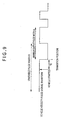
- Fig. 6 is diagram, showing the waveform of the vehicle velocity pulse signal in the stopping process of the vehicle.
- minimum output velocity computing section 24 inputs a signal output from state judgment section 23.
- minimum output velocity computing section 24 reads the pulse widths A and pulse widths B recorded in pulse width recording section 29 of database 20. Then as shown in Fig. 6, of the pulse widths A and pulse widths B that have been read, the minimum output pulse width A, which was recorded immediately prior to the stopping of the vehicle that was judged, is acquired.
- minimum output velocity computing section 24 After acquiring the minimum output pulse width A in step S3, minimum output velocity computing section 24 reads the distance factor value stored in distance factor storage section 26 of database 20. Then based on the acquired minimum output pulse width A and the distance factor value that was read, the minimum output velocity in the stopping process is computed by the following [Equation 4] (step S4).
- Minimum output velocity Distance factor value / minimum output pulse width A
- Minimum output velocity computing section 24 also outputs the computed minimum output velocity to movement condition computing section 25.
- step S4 movement condition computing section 25 acquires this minimum output velocity and computes the relative movement distance in the stopping process of the vehicle (step S5).
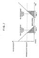
- Fig. 7 is a diagram for explaining the computation of the relative movement distance.
- the relative movement distance (stop) computed in the above manner corresponds to the area of the black-filled triangle shown in Fig. 7. Also as shown in Fig. 7, the relative movement velocity of the vehicle is computed by a first order approximation function and based on the minimum output velocity and the stop position (time) of the vehicle.
- velocity information acquisition section 21 performs measurement of the pulse widths of the input vehicle velocity pulse signal (step S1). That is, velocity information acquisition section 21 performs pulse width measurement regardless of whether the vehicle is stopping or starting.
- state judgment section 23 judges whether or not the vehicle has started (step S6). More specifically, state judgment section 23 acquires, from state information acquisition section 22, the state information based on the sensor signal output from acceleration sensor 12, that is, the vehicle's acceleration. State judgment section 23 judges the vehicle's start position (time) as being the position at which the acceleration of the vehicle increases or decreases from the position at which the acceleration was stabilized at substantially 0.
- step S6 If in step S6, state judgment section 23 does not judge the vehicle to be in the start state, a return to step S1 is performed and the measurement of pulse widths by velocity information acquisition section 21 is continued.
- step S6 state judgment section 23 judges the vehicle to be in the start state, minimum output velocity computing section 24 judges whether or not a pulse width recorded in pulse width recording section 29 of database 20 is a pulse width that is based on a leading edge or a trailing edge of the vehicle velocity pulse signal recognized at velocity information acquisition section 21 after judgment of the start state of the vehicle (step S7).
- Fig. 9 is diagram, showing the waveform of the vehicle velocity pulse signal in the starting process of the vehicle.
- Minimum output velocity computing section 24 inputs a signal output from state judgment section 23 and reads the pulse widths A and pulse widths B recorded in pulse width recording section 29 of database 20.
- Minimum output velocity computing section 24 judges whether or not a pulse width A or pulse width B that has been read is a pulse width that is based on a leading edge or a trailing edge of the vehicle velocity pulse signal recognized at velocity information acquisition section 21 after judgment of the start state of the vehicle, that is, whether or not a pulse width is the second recorded pulse width such as shown in Fig. 9.
- step S7 If the pulse width that has been read in step S7 is not the second recorded pulse width after judgment of the start state of the vehicle, a return to step S1 is performed and pulse width measurement is continued. That is, if a pulse width that is the first pulse width that was recorded after the starting of the vehicle or a pulse width that was recorded prior to the starting of the vehicle is read, pulse width measurement is continued.
- step S7 If the pulse width that has been read in step S7 is the second recorded pulse width after the starting of the vehicle, this pulse width is acquired as a minimum output pulse width A (Fig. 5) (step S8). That is, pulse width measurement is continued until the second pulse width after the starting of the vehicle is recorded.
- minimum output velocity computing section 24 After acquiring the minimum output pulse width A in step S8, minimum output velocity computing section 24 reads the distance factor value stored in distance factor storage section 26 of database 20. Then based on the acquired minimum output pulse width A and the distance factor value that was read, the minimum output velocity (starting process) is computed by [Equation 4] in the same manner as in the case of the vehicle stopping process described above (step S9). Minimum output velocity computing section 24 also outputs the computed minimum output velocity (starting process) to movement condition computing section 25.
- step S9 movement condition computing section 25 acquires this minimum output velocity (starting process) and computes the relative movement distance in the starting process of the vehicle (step S10).
- the relative movement distance (start) computed in the above manner corresponds to the area of the black-filled triangle shown in Fig. 7. Also, the relative movement velocity of the vehicle is computed in the same manner as in the case of the vehicle stopping process described above.
- the relative movement distance of the vehicle in a state in which the vehicle velocity pulse signal cannot be acquired by velocity information acquisition section 21 is computed. Also, the relative movement velocity of the vehicle is computed by a first order approximation function and based on the computed minimum output velocity and the stopping or starting of the vehicle.
- movement condition computing section 25 computes the relative movement distance of the vehicle by section of [Equation 2] and computes the relative movement velocity of the vehicle by section of [Equation 3].
- velocity information acquisition section 21 computes pulse widths from the input vehicle velocity pulse signal.
- the computed pulse widths are recorded in velocity information recording section 27.
- the stop or start state of the vehicle is judged by state judgment section 23.
- minimum output velocity computing section 24 reads the pulse widths recorded in velocity information recording section 27 and selects the minimum output pulse width based on the stop position (time) or start position (time) of the vehicle. Also, based on the computed minimum output pulse width and the distance factor value, minimum output velocity computing section 24 computes the minimum output velocity in a state in which the vehicle velocity pulse signal can be acquired.
- Movement condition computing section 25 then computes the relative movement distance of the vehicle based on the computed minimum output velocity and the vehicle's stop position (time) or start position (time) that was judged by state judgment section 23. That is, even in a state in which the vehicle velocity pulse signal cannot be acquired at velocity information acquisition section 21, the relative movement distance can be computed in an appropriate and yet simple manner.
- the pulse widths acquired at velocity information acquisition section 21 can be recorded appropriately.
- Minimum output velocity computing section 24 can thus compute the minimum output velocity appropriately based on these recorded pulse widths.
- velocity information recording section 27 records the two types of pulse widths of pulse widths A, which are based on the state transitions of the leading edges of the vehicle velocity pulse signal acquired at velocity information acquisition section 21, and pulse widths B, which are based on the state transitions of the trailing edges.
- minimum output velocity computing section 24 can select an appropriate minimum output pulse width. Minimum output velocity computing section 24 can thus compute the minimum output velocity appropriately.
- minimum output velocity computing section 24 selects, as the minimum output pulse width, the pulse width recorded immediately prior to the stopping of the vehicle. Minimum output velocity computing section 24 can thus compute an appropriate minimum output velocity.
- minimum output velocity computing section 24 selects, as the minimum output pulse width, the second recorded pulse width after the starting of the vehicle. Minimum output velocity computing section 24 can thus compute an appropriate minimum output velocity that does not contain error.
- minimum output velocity computing section 24 reads the pulse widths recorded in pulse width recording section 29 and selects the minimum output pulse width when state judgment section 23 judges the vehicle to be in a stop state or start state. Minimum output velocity computing section 24 then computes the minimum output velocity based on this minimum output pulse width.
- the second embodiment differs in that minimum output velocity computing section 24 computes the minimum output velocity based on acceleration information.
- Fig. 10 is a diagram, showing the general arrangement of a movement distance detection section 13, which is a movement condition computing device of the second embodiment.
- 13 is a movement distance detection section.
- This movement distance detection section 13 is equipped with a processing unit 19 and a database 20.
- processing unit 19 is also equipped with an acceleration information acquisition section 30.
- Acceleration information acquisition section 30 acquires the sensor output from an acceleration sensor 12 and converts this sensor output into acceleration data of the vehicle. The acceleration data resulting from the conversion are then recorded in association with the acquisition position (time) in database 20.
- minimum output velocity computing section 24 computes the minimum output velocity immediately prior to the stopping of the vehicle or after the starting of the vehicle based on the acceleration data recorded in database 20.
- movement condition computing section 25 computes the relative movement distance based on the minimum output velocity, computed at minimum output velocity computing section 24, and on the period in which the vehicle velocity pulse signal could not be acquired by velocity information acquisition section 21.
- database 20 is also equipped with an acceleration information recording section 31.
- This acceleration information recording section 31 is arranged, for example, from a rewritable SRAM, etc. This acceleration information recording section 31 records the acceleration data, obtained by conversion at acceleration information acquisition section 30, in association with the acquisition position (time).
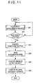
- the movement condition computing method of movement distance detection section 13 shall now be described with reference to the flowcharts shown in Figs. 11 and 12. First, the movement distance calculation method of the stopping process of the vehicle shall be described with reference to Fig. 11.
- velocity information acquisition section 21 performs measurement of pulse widths (step S21).
- acceleration data are acquired by acceleration information acquisition section 30.
- the acquired acceleration data are recorded in acceleration information recording section 31.
- step S21 While pulse width measurement is being carried out in step S21, whether or not the vehicle has stopped is judged by state judgment section 23 in the same manner as in the first embodiment (step S22).
- step S22 state judgment section 23 judges that the vehicle is not in the stop state, a return to step S21 is performed and pulse width measurement by velocity information acquisition section 21 is continued.
- step S22 state judgment section 23 judges that the vehicle is in the stop state
- minimum output velocity computing section 24 acquires, from among the transition positions recorded in transition position recording section 28 of database 20, the transition position recorded immediately prior to the stopping of the vehicle (step S23).
- minimum output velocity computing section 24 reads, from among the acceleration data recorded in acceleration information recording section 31, the acceleration data corresponding to the transition position acquired in step S23 (step S24).
- minimum output velocity computing section 24 converts the acquired acceleration data into velocity data and computes the acceleration sensor velocity as the minimum output velocity as shown in Fig. 13 (step S25).
- movement condition computing section 25 acquires the acceleration sensor velocity computed in step S25. Movement condition computing section 25 also acquires, from among the transition positions recorded in transition position recording section 28 of database 20, the transition position (time) at which the logic of the vehicle velocity pulse signal changed immediately prior to the stopping of the vehicle. Furthermore, the stop position (time) of the vehicle that was judged by state judgment section 23 is acquired. Then based on the acquired transition position (time) and the vehicle stop position (time), movement condition computing section 25 computes the period T1 (Fig. 13) in which the vehicle velocity pulse signal could not be acquired at velocity information acquisition section 21.
- Movement condition computing section 25 then computes the relative movement distance in the vehicle stopping process based on the acceleration sensor velocity and period T1 and by section of the following [Equation 7] (step S26).
- Relative movement distance (stop) Acceleration sensor velocity ⁇ Period T1 / 2
- the relative movement distance (stop) that is calculated in the above manner corresponds to the area of the black-filled triangle shown in Fig. 13.
- the computing of the relative movement velocity is carried out in the same manner as in the first embodiment.
- velocity information acquisition section 21 carries out measurement of pulse widths (step S21). That is regardless of the stopping or starting of the vehicle, velocity information acquisition section 21 carries out pulse width measurement. Acquisition of acceleration data by acceleration information acquisition section 30 is carried out in parallel to pulse width measurement by velocity information acquisition section 21 in this case as well. The acquired acceleration data are recorded in acceleration information recording section 31.
- state judgment section 23 judges whether or not the vehicle has started (step S27).
- step S27 state judgment section 23 does not judge the vehicle to be in the start state, a return to step S21 is performed.
- step S27 state judgment section 23 judges the vehicle to be in the start state
- minimum output velocity computing section 24 reads the transition positions recorded in transition position recording section 28 of database 20 and then judges whether or not a transition position was recorded after the starting of the vehicle (step S28).
- step S28 it is judged that a transition position has not been recorded after the starting of the vehicle, a return to step S21 is performed again.
- step S28 If in step S28, it is judged that a transition position was recorded after the starting of the vehicle, minimum output velocity computing section 24 acquires the transition position recorded immediately after the starting of the vehicle (step S29).
- minimum output velocity computing section 24 reads, from among the acceleration data recorded in acceleration information recording section 31, the acceleration data corresponding to the transition position acquired in step S29 (step S30).
- minimum output velocity computing section 24 converts the acquired acceleration data into velocity data and computes the acceleration sensor velocity (Fig. 13) as the minimum output velocity (step S31). Then after this step S31, movement condition computing section 25 acquires the acceleration sensor velocity that was computed in step S31 and also acquires, from among the transition positions recorded in transition position recording section 28, the transition position that was recorded immediately after the starting of the vehicle. Furthermore, based on the vehicle start position judged by state judgment section 23 and the acquired transition position, movement condition computing section 25 computes the period T2 (Fig. 13) in which the vehicle velocity pulse signal cannot be acquired at velocity information acquisition section 21.
- movement condition computing section 25 computes the relative movement distance in the vehicle starting process by the following [Equation 8] (step S32).
- Relative movement distance (start) Acceleration sensor velocity ⁇ Period T2 / 2
- the relative movement distance (start) computed in the above manner corresponds to the area of the black-filled triangle shown in Fig. 13. Also, the relative movement velocity is computed in the same manner as in the first embodiment.
- the relative movement distances or relative movement velocities prior to state judgment section 23 judging the vehicle to be stopped and after state judgment section 23 judging the vehicle to have started are computed in the same manner as in the first embodiment.
- acceleration information acquisition section 30 converts the sensor output from the acceleration sensor into acceleration data.
- the acceleration data are recorded in acceleration information recording section 31.
- Minimum output velocity computing section 24 acquires the transition position corresponding to a state in which velocity information acquisition section 21 cannot acquire the vehicle velocity pulse signal.
- the acceleration data corresponding to this transition position is read and converted into velocity data.
- the minimum output velocity computing section can compute an appropriate minimum output velocity based on the velocity data resulting from the conversion.
- movement condition computing section 25 can compute the relative movement distance or relative movement velocity of the vehicle appropriately even in a state in which velocity information acquisition section 21 cannot acquire the vehicle velocity pulse signal during travel of the vehicle.
- movement condition computing section 25 uses an approximate computing equation to compute the relative movement distance based on the minimum output velocity in a state in which the vehicle velocity pulse signal can be acquired by velocity information acquisition section 21 and on the stop position (time) or start position (time) judged by state judgment section 23.
- the third embodiment differs in that movement condition computing section 25 converts acceleration information into velocity information in a state in which velocity information acquisition section 21 cannot acquire the vehicle velocity pulse signal and integrates the computed velocity information to compute the relative movement distance.
- Fig. 14 is a diagram, showing the general arrangement of a movement distance detection section 13, which is a movement condition computing device of the third embodiment.
- 13 is the movement distance detection section, and this movement distance detection section 13 is equipped with a processing unit 19 and a database 20.
- processing unit 19 is also equipped with an acceleration information acquisition section 30, a conversion process section 32, and a distance correction section 33.
- Acceleration information acquisition section 30 acquires the sensor signal output from an acceleration sensor and converts this input sensor signal into acceleration data.
- the acceleration data resulting from the conversion are recorded in database 20.
- the converted acceleration data are also output to state judgment section 23 and conversion process section 32.
- state judgment section 23 judges the stop or start state of the vehicle. Upon judging the vehicle to be in the stop or start state, state judgment section 23 outputs a signal to conversion process section 32.
- Conversion process section 32 reads the acceleration data recorded in an acceleration information recording section 31 and coverts the read acceleration data into velocity data. The velocity data resulting from the conversion are output to movement condition computing section 25.
- Movement condition computing section 25 integrates the velocity data output from conversion processing section 32 and computes the relative movement distance of the vehicle. The computed relative movement distance is output to distance correction section 33.
- Distance correction section 33 corrects the relative movement distance output from movement condition computing section 25. If there is an error in the acceleration data acquired at acceleration information acquisition section 30, distance correction section 33 computes a relative movement distance correction value based on the error value and then corrects the relative movement distance by subtracting the correction value from the relative movement distance.
- database 20 is also equipped with acceleration information recording section 31.
- Acceleration information recording section 31 is arranged, for example, from a rewritable SRAM, etc.
- This acceleration information recording section 31 records the acceleration data acquired at acceleration information acquisition section 30.
- the movement condition computing method of movement distance detection section 13 shall now be described with reference to the flowcharts shown in Figs. 15 and 16. First, the movement condition computing method for the stopping process of the vehicle shall be described with reference to Fig. 15.
- velocity information acquisition section 21 performs measurement of pulse widths (step S41).
- acceleration data are acquired by acceleration information acquisition section 30.
- the acquired acceleration data are recorded in acceleration information recording section 31.
- state judgment section 23 acquires acceleration data from acceleration information acquisition section 30 and judges whether or not the vehicle is in the stop state (step S42). More specifically, state judgment section 23 reads the acceleration data values successively and judges the state, in which this value decreases to close to 0 and stabilizes, as being the stop state of the vehicle.
- step S42 state judgment section 23 judges that the vehicle is not in the stop state, a return to step S41 is performed.
- step S42 If in step S42, it is judged that the vehicle is in the stop state, conversion process section 32 inputs a signal from state judgment section 23. Thereafter, conversion process section 32 reads the transition position recorded in transition position recording section 28 of database 20 and acquires the transition position recorded immediately prior to the stopping of the vehicle (step S43).
- step S43 conversion process section 32 successively reads the acceleration data recorded in acceleration information recording section 31 in a period T1 (Fig. 17), from the acquired transition position to the vehicle stop position (step S44).
- step S44 conversion process section 32 converts the acquired acceleration data into velocity data successively (step S45).
- the velocity data resulting from the conversion are successively output to movement condition computing section 25.
- movement condition computing section 25 integrates the acquired velocity data to compute the relative movement distance in the vehicle stopping process (step S46).
- the relative movement distance that has thus been computed is output to distance correction section 33.
- the area of the black-filled triangle corresponds to the relative movement distance (stop).
- the acceleration varies in a manner such that the velocity data values resulting from conversion at conversion process section 32 do not exhibit a first-order-function-like straight line. Even in such a case, an appropriate relative movement distance is computed by integrating the velocity data.
- Distance correction section 33 acquires acceleration data when it has been judged at state judgment section 23 that the vehicle is in the stop state and then judges whether or not error is contained in the acceleration data values (step S47).
- step S47 If it is judged in step S47 that error is not contained, correction is not performed on the relative movement distance (stop) that was computed in step S46.
- step S47 If in step S47, it is judged that error is contained, distance correction section 33 performs correction of the relative movement distance that was computed in step S46 (step S48).
- Fig. 18 is a diagram for explaining the method of correcting the relative movement distance.
- Error may occur in acceleration sensor 12 due to temperature characteristics, vibration of the vehicle, etc., and the acceleration data acquired at acceleration information acquisition section 30 may thus contain error.
- state judgment section 23 judges the position at which the acceleration data values decrease and stabilize as the vehicle stop position.
- the velocity at the stop state may be erroneous.
- movement condition computing section 27 integrates the velocity data during the period T from the vehicle stop position to the position at which the vehicle velocity pulse signal cannot be acquired at velocity information acquisition section 21. That is, movement condition computing section 27 computes the area of the black-filled triangles shown in Fig. 18 (A) as the relative movement distance. The computed relative movement distance thus contains error.
- velocity information acquisition section 21 carries out measurement of pulse widths (step S41). That is regardless of the stopping or starting of the vehicle, velocity information acquisition section 21 carries out pulse width measurement.
- acquisition of acceleration data by acceleration information acquisition section 30 is carried out in parallel to pulse width measurement by velocity information acquisition section 21.
- the acquired acceleration data are recorded in acceleration information recording section 31.
- state judgment section 23 acquires acceleration data from acceleration information acquisition section 30 and judges whether or not the vehicle has started (step S49). More specifically, state judgment section 23 reads the acceleration data values successively and judges the state, in which these values increase from the state in which the values are stable at close to 0, as being the start state of the vehicle.
- step S49 state judgment section 23 does not judge the vehicle to be in the start state, a return to step S41 is performed.
- step S49 state judgment section 23 judges the vehicle to be in the start state
- conversion process section 32 inputs the signal from state judgment section 23. Thereafter, conversion process section 32 reads the transition positions recorded in transition position recording section 28 of database 20 and then judges whether or not a transition position was recorded after the starting of the vehicle (step S50).
- step S50 it is judged that a transition position has not been recorded after the starting of the vehicle, a return to step S41 is performed again.
- step S50 If in step S50, it is judged that a transition position was recorded after the starting of the vehicle, conversion process section 32 acquires the transition position recorded immediately after the starting of the vehicle (step S51).
- step S51 conversion process section 32 successively reads the acceleration data recorded in acceleration information recording section 31 during a period T2 (Fig. 17), from the acquired transition position to the vehicle start position (step S52).
- conversion process section 32 converts the acquired acceleration data into velocity data successively as was done in step S45 (step S53).
- the converted velocity data are successively output to movement condition computing section 25.
- movement condition computing section 25 integrates the acquired velocity data successively to compute the relative movement distance in the vehicle starting process (step S54).
- the relative movement distance that has thus been computed is output to distance correction section 33.
- Distance correction section 33 acquires acceleration data when it has been judged at state judgment section 23 that the vehicle is in the start state and then judges whether or not error is contained in the acceleration data values (step S55).
- step S55 If it is judged in step S55 that error is not contained, correction is not performed on the relative movement distance that was computed in step S54.
- step S55 If in step S55, it is judged that error is contained, correction is performed on the relative movement distance that was computed in step S54. More specifically, the error velocity (Fig. 16) at the vehicle's start position is acquired. Then based on this error velocity and the period T, from the position at which velocity information acquisition section 21 cannot acquire the vehicle velocity pulse signal to the vehicle's start position, the correction value is computed by the above-described [Equation 9]. Also based on this correction value and the relative movement distance computed in step S54, the relative movement distance is corrected by the above-described [Equation 10] (step S56).
- the relative movement distance of the vehicle in a state in which velocity information acquisition section 21 cannot acquire the vehicle velocity pulse signal is computed.
- the relative movement distances or relative movement velocities prior to the state judgment section judging the vehicle to be stopped and after the state judgment section judging the vehicle to have started are computed in the same manner as in the first embodiment.
- the relative movement velocity is computed based on the computed minimum output velocity and the time at which the vehicle has stopped or started and using a first-order approximation function.
- acceleration information acquisition section 30 acquires acceleration data.
- the acceleration data acquired at acceleration information acquisition section 30 are recorded in acceleration information recording section 31.
- the acceleration data acquired at acceleration information acquisition section 30 are furthermore output to state judgment section 23.
- state judgment section 23 can judge the stop or start state of the vehicle.
- conversion process section 32 successively converts the acceleration data, recorded in acceleration information recording section 31 from the vehicle stop position or start position to the position at which the vehicle velocity pulse signal can be acquired by velocity information acquisition section 21, into velocity data.
- Movement condition computing section 25 can then compute the relative movement distance by successively integrating the velocity data. The relative movement distance can thus be computed appropriately even for a period in which velocity information acquisition section 21 cannot acquire the vehicle velocity pulse signal during travel of the vehicle.
- movement condition computing section 27 can compute the vehicle's relative movement distance more accurately even during a period in which velocity information acquisition section 21 cannot acquire the vehicle velocity pulse signal during travel of the vehicle.
- Distance correction section 33 judges whether or not the relative movement distance needs to be corrected based on the acceleration data during the judgment of the stop or start state of the vehicle at state judgment section 23. If there is an error in the acceleration data, a relative movement distance correction value is computed based on the error velocity in the stop or start state of the vehicle. The relative movement distance is then corrected by subtracting the relative movement distance correction value. The vehicle's relative movement distance can thereby be computed even more accurately even during a period in which velocity information acquisition section 21 cannot acquire the vehicle velocity pulse signal during travel of the vehicle.
- the sensor output from an acceleration sensor is used as the state information that indicates the stop or start state of the vehicle, this invention is not limited thereto and a gyro or other sensor may be used instead.
- the stop or start state of the vehicle is judged at the state judgment section, this invention is not limited thereto, and an arrangement is also possible wherein the stop or start state of the vehicle is judged when the pulse width that is being acquired at the velocity information acquisition section is found by a timer, etc., to have elapsed for a predetermined period.
- a rectangular wave is used as the vehicle velocity pulse signal acquired at the velocity information acquisition section, this invention is not limited thereto, and a sine wave, triangular wave, sawtooth wave, etc., may be used instead.
- the computed relative movement distance is not corrected, this invention is not limited thereto, and these embodiments may be equipped with a distance correction section or other correction function as in the above-described third embodiment.
- the relative movement distance or the relative movement velocity is computed based on the pulse width or number of vehicle velocity pulses acquired by the velocity information acquisition section when the velocity information acquisition section can acquire the vehicle velocity pulse signal
- this invention is not limited thereto. That is, an arrangement is also possible wherein the relative movement distance or the relative movement velocity are computed based on the acceleration information acquired at the acceleration information acquisition section.
Applications Claiming Priority (2)
| Application Number | Priority Date | Filing Date | Title |
|---|---|---|---|
| JP2002127400 | 2002-04-26 | ||
| JP2002127400A JP4024075B2 (ja) | 2002-04-26 | 2002-04-26 | 移動状況算出装置、この方法、このプログラム、このプログラムを記録する記録媒体、および、ナビゲーション装置 |
Publications (3)
| Publication Number | Publication Date |
|---|---|
| EP1357354A2 true EP1357354A2 (de) | 2003-10-29 |
| EP1357354A3 EP1357354A3 (de) | 2004-01-07 |
| EP1357354B1 EP1357354B1 (de) | 2005-03-30 |
Family
ID=28786840
Family Applications (1)
| Application Number | Title | Priority Date | Filing Date |
|---|---|---|---|
| EP03252628A Expired - Lifetime EP1357354B1 (de) | 2002-04-26 | 2003-04-25 | Bewegungszustandsbestimmung |
Country Status (4)
| Country | Link |
|---|---|
| US (1) | US6829525B2 (de) |
| EP (1) | EP1357354B1 (de) |
| JP (1) | JP4024075B2 (de) |
| DE (1) | DE60300435T2 (de) |
Cited By (2)
| Publication number | Priority date | Publication date | Assignee | Title |
|---|---|---|---|---|
| WO2010023165A1 (de) * | 2008-08-25 | 2010-03-04 | Continental Automotive Gmbh | Verfahren und vorrichtung zur ermittlung eines bewegungszustands eines fahrzeugs mit einem beschleunigungssensor |
| WO2016174612A1 (en) * | 2015-04-28 | 2016-11-03 | Ecole Polytechnique Federale De Lausanne (Epfl) | High precision trajectory and speed sensor and measuring method |
Families Citing this family (12)
| Publication number | Priority date | Publication date | Assignee | Title |
|---|---|---|---|---|
| KR100609958B1 (ko) * | 2004-07-29 | 2006-08-08 | 엘지전자 주식회사 | 차속펄스계수의 자기 튜닝방법 |
| JP2006317287A (ja) * | 2005-05-12 | 2006-11-24 | Denso Corp | 車両用現在位置決定装置 |
| JP2007055298A (ja) * | 2005-08-22 | 2007-03-08 | Calsonic Kansei Corp | 車両用データ記録装置 |
| JP4824522B2 (ja) * | 2006-10-18 | 2011-11-30 | クラリオン株式会社 | 車載装置 |
| JP4345842B2 (ja) * | 2007-04-26 | 2009-10-14 | アイシン・エィ・ダブリュ株式会社 | 車両位置情報提供装置、車両位置情報提供方法及びコンピュータプログラム |
| JP2010117756A (ja) * | 2008-11-11 | 2010-05-27 | Kanack Planning Corp | 車速信号供給装置、カーナビゲーションシステム、及び、これらを含む自動車 |
| WO2010137136A1 (ja) * | 2009-05-27 | 2010-12-02 | トヨタ自動車株式会社 | 車両 |
| JP6094026B2 (ja) * | 2011-03-02 | 2017-03-15 | セイコーエプソン株式会社 | 姿勢判定方法、位置算出方法及び姿勢判定装置 |
| JP5891120B2 (ja) * | 2012-06-22 | 2016-03-22 | パイオニア株式会社 | 速度算出装置、速度算出方法、速度算出プログラム、および記録媒体 |
| JP5920056B2 (ja) * | 2012-06-28 | 2016-05-18 | 株式会社デンソー | 走行距離積算装置 |
| JP6545108B2 (ja) * | 2016-01-14 | 2019-07-17 | アルパイン株式会社 | 駐車支援装置および駐車支援方法 |
| JP6525047B2 (ja) * | 2017-12-27 | 2019-06-05 | 株式会社Jvcケンウッド | 速度演算装置 |
Citations (5)
| Publication number | Priority date | Publication date | Assignee | Title |
|---|---|---|---|---|
| US4922447A (en) * | 1985-10-09 | 1990-05-01 | Alcatel N.V. | Device for measuring the distance travelled and the speed of a rail vehicle |
| EP0488594A1 (de) * | 1990-11-30 | 1992-06-03 | Sumitomo Electric Industries, Limited | Einrichtung zur Driftfehlerkorrektur eines Gierwinkelgeschwindigkeitssensors |
| JPH10170303A (ja) * | 1996-12-10 | 1998-06-26 | Toyo Commun Equip Co Ltd | 加速度センサを用いた速度・距離計測器 |
| DE19916529C1 (de) * | 1999-04-13 | 2001-01-11 | Mannesmann Vdo Ag | Meßwertgeber für ein mobiles Navigationssystem |
| EP1256810A2 (de) * | 2001-05-07 | 2002-11-13 | Pioneer Corporation | Verfahren und Vorrichtung zur Nachweisung des Pulsabfalls einer Fahrzeugsgeschwindigkeit, für ein mobiles Navigationssystem und ein Computer Program dafür |
Family Cites Families (3)
| Publication number | Priority date | Publication date | Assignee | Title |
|---|---|---|---|---|
| US3996590A (en) * | 1961-02-02 | 1976-12-07 | Hammack Calvin M | Method and apparatus for automatically detecting and tracking moving objects and similar applications |
| US6218961B1 (en) * | 1996-10-23 | 2001-04-17 | G.E. Harris Railway Electronics, L.L.C. | Method and system for proximity detection and location determination |
| US6377888B1 (en) * | 2000-04-03 | 2002-04-23 | Disney Enterprises, Inc. | System for controlling movement of a vehicle |
-
2002
- 2002-04-26 JP JP2002127400A patent/JP4024075B2/ja not_active Expired - Fee Related
-
2003
- 2003-04-25 EP EP03252628A patent/EP1357354B1/de not_active Expired - Lifetime
- 2003-04-25 US US10/423,039 patent/US6829525B2/en not_active Expired - Lifetime
- 2003-04-25 DE DE60300435T patent/DE60300435T2/de not_active Expired - Lifetime
Patent Citations (5)
| Publication number | Priority date | Publication date | Assignee | Title |
|---|---|---|---|---|
| US4922447A (en) * | 1985-10-09 | 1990-05-01 | Alcatel N.V. | Device for measuring the distance travelled and the speed of a rail vehicle |
| EP0488594A1 (de) * | 1990-11-30 | 1992-06-03 | Sumitomo Electric Industries, Limited | Einrichtung zur Driftfehlerkorrektur eines Gierwinkelgeschwindigkeitssensors |
| JPH10170303A (ja) * | 1996-12-10 | 1998-06-26 | Toyo Commun Equip Co Ltd | 加速度センサを用いた速度・距離計測器 |
| DE19916529C1 (de) * | 1999-04-13 | 2001-01-11 | Mannesmann Vdo Ag | Meßwertgeber für ein mobiles Navigationssystem |
| EP1256810A2 (de) * | 2001-05-07 | 2002-11-13 | Pioneer Corporation | Verfahren und Vorrichtung zur Nachweisung des Pulsabfalls einer Fahrzeugsgeschwindigkeit, für ein mobiles Navigationssystem und ein Computer Program dafür |
Non-Patent Citations (1)
| Title |
|---|
| PATENT ABSTRACTS OF JAPAN vol. 1998, no. 11, 30 September 1998 (1998-09-30) & JP 10 170303 A (TOYO COMMUN EQUIP CO LTD), 26 June 1998 (1998-06-26) * |
Cited By (3)
| Publication number | Priority date | Publication date | Assignee | Title |
|---|---|---|---|---|
| WO2010023165A1 (de) * | 2008-08-25 | 2010-03-04 | Continental Automotive Gmbh | Verfahren und vorrichtung zur ermittlung eines bewegungszustands eines fahrzeugs mit einem beschleunigungssensor |
| US9234910B2 (en) | 2008-08-25 | 2016-01-12 | Continental Automotive Gmbh | Method and device for determining a state of motion of a vehicle comprising an acceleration sensor |
| WO2016174612A1 (en) * | 2015-04-28 | 2016-11-03 | Ecole Polytechnique Federale De Lausanne (Epfl) | High precision trajectory and speed sensor and measuring method |
Also Published As
| Publication number | Publication date |
|---|---|
| EP1357354B1 (de) | 2005-03-30 |
| EP1357354A3 (de) | 2004-01-07 |
| DE60300435T2 (de) | 2006-02-09 |
| US6829525B2 (en) | 2004-12-07 |
| JP2003322533A (ja) | 2003-11-14 |
| DE60300435D1 (de) | 2005-05-04 |
| US20030236607A1 (en) | 2003-12-25 |
| JP4024075B2 (ja) | 2007-12-19 |
Similar Documents
| Publication | Publication Date | Title |
|---|---|---|
| JP3570372B2 (ja) | 車両用現在位置検出装置、車両用現在位置表示装置、ナビゲーション装置および記録媒体 | |
| EP1178329B1 (de) | Verfahren und Gerät zur Korrektur der Position eines bewegbaren Körpers in einem Navigationssystem | |
| JP3449240B2 (ja) | 車両用現在位置検出装置、車両用現在位置表示装置、ナビゲーション装置および記録媒体 | |
| JP3984112B2 (ja) | 車両位置修正装置および距離しきい値設定方法 | |
| EP1357354B1 (de) | Bewegungszustandsbestimmung | |
| US6904383B2 (en) | Distance factor learning device, distance factor learning method, distance factor learning program, recording medium recording said program, movement condition computing device, and present position computing device | |
| US6766247B2 (en) | Position determination method and navigation device | |
| JP3112405B2 (ja) | 車両位置検出装置 | |
| JPH10307036A (ja) | ナビゲーション装置 | |
| JP4316820B2 (ja) | 車載ナビゲーション装置及び方位測定方法 | |
| JP4473059B2 (ja) | ナビゲーション装置 | |
| JPH09196691A (ja) | ナビゲーション装置 | |
| US6128572A (en) | Vehicle direction correcting apparatus | |
| JP3572828B2 (ja) | ナビゲーション装置 | |
| JP3012501B2 (ja) | 車両位置検出装置 | |
| EP0601712A1 (de) | Navigationssystem | |
| JP3545798B2 (ja) | 現在位置算出装置 | |
| JP3596939B2 (ja) | 現在位置算出装置 | |
| JP3126751B2 (ja) | 距離補正係数の自動補正装置 | |
| JP3656662B2 (ja) | 現在位置算出装置 | |
| JP3584543B2 (ja) | ナビゲーション装置 | |
| JPH08327377A (ja) | ナビゲーション装置 | |
| JPH1073442A (ja) | ナビゲーション装置 | |
| JPH04315914A (ja) | 車両の走行距離算出装置 | |
| JP3606703B2 (ja) | 車載ナビゲーション装置 |
Legal Events
| Date | Code | Title | Description |
|---|---|---|---|
| PUAI | Public reference made under article 153(3) epc to a published international application that has entered the european phase |
Free format text: ORIGINAL CODE: 0009012 |
|
| AK | Designated contracting states |
Kind code of ref document: A2 Designated state(s): AT BE BG CH CY CZ DE DK EE ES FI FR GB GR HU IE IT LI LU MC NL PT RO SE SI SK TR |
|
| AX | Request for extension of the european patent |
Extension state: AL LT LV MK |
|
| PUAL | Search report despatched |
Free format text: ORIGINAL CODE: 0009013 |
|
| RIC1 | Information provided on ipc code assigned before grant |
Ipc: 7G 01P 3/54 B Ipc: 7G 01C 22/00 B Ipc: 7G 01C 21/10 A Ipc: 7G 01P 3/48 B |
|
| AK | Designated contracting states |
Kind code of ref document: A3 Designated state(s): AT BE BG CH CY CZ DE DK EE ES FI FR GB GR HU IE IT LI LU MC NL PT RO SE SI SK TR |
|
| AX | Request for extension of the european patent |
Extension state: AL LT LV MK |
|
| 17P | Request for examination filed |
Effective date: 20040628 |
|
| GRAP | Despatch of communication of intention to grant a patent |
Free format text: ORIGINAL CODE: EPIDOSNIGR1 |
|
| AKX | Designation fees paid |
Designated state(s): DE FR GB |
|
| GRAS | Grant fee paid |
Free format text: ORIGINAL CODE: EPIDOSNIGR3 |
|
| GRAA | (expected) grant |
Free format text: ORIGINAL CODE: 0009210 |
|
| AK | Designated contracting states |
Kind code of ref document: B1 Designated state(s): DE FR GB |
|
| REG | Reference to a national code |
Ref country code: GB Ref legal event code: FG4D |
|
| REF | Corresponds to: |
Ref document number: 60300435 Country of ref document: DE Date of ref document: 20050504 Kind code of ref document: P |
|
| REG | Reference to a national code |
Ref country code: IE Ref legal event code: FG4D |
|
| PLBE | No opposition filed within time limit |
Free format text: ORIGINAL CODE: 0009261 |
|
| STAA | Information on the status of an ep patent application or granted ep patent |
Free format text: STATUS: NO OPPOSITION FILED WITHIN TIME LIMIT |
|
| ET | Fr: translation filed | ||
| 26N | No opposition filed |
Effective date: 20060102 |
|
| REG | Reference to a national code |
Ref country code: FR Ref legal event code: PLFP Year of fee payment: 14 |
|
| REG | Reference to a national code |
Ref country code: FR Ref legal event code: PLFP Year of fee payment: 15 |
|
| REG | Reference to a national code |
Ref country code: FR Ref legal event code: PLFP Year of fee payment: 16 |
|
| PGFP | Annual fee paid to national office [announced via postgrant information from national office to epo] |
Ref country code: GB Payment date: 20220303 Year of fee payment: 20 |
|
| PGFP | Annual fee paid to national office [announced via postgrant information from national office to epo] |
Ref country code: FR Payment date: 20220308 Year of fee payment: 20 |
|
| PGFP | Annual fee paid to national office [announced via postgrant information from national office to epo] |
Ref country code: DE Payment date: 20220302 Year of fee payment: 20 |
|
| REG | Reference to a national code |
Ref country code: DE Ref legal event code: R071 Ref document number: 60300435 Country of ref document: DE |
|
| REG | Reference to a national code |
Ref country code: GB Ref legal event code: PE20 Expiry date: 20230424 |
|
| PG25 | Lapsed in a contracting state [announced via postgrant information from national office to epo] |
Ref country code: GB Free format text: LAPSE BECAUSE OF EXPIRATION OF PROTECTION Effective date: 20230424 |