EP1356990A1 - Kfz-Sicherheitseinrichtung, wie Laderaumabdeckung, Trennnetz od. dgl. - Google Patents
Kfz-Sicherheitseinrichtung, wie Laderaumabdeckung, Trennnetz od. dgl. Download PDFInfo
- Publication number
- EP1356990A1 EP1356990A1 EP03004795A EP03004795A EP1356990A1 EP 1356990 A1 EP1356990 A1 EP 1356990A1 EP 03004795 A EP03004795 A EP 03004795A EP 03004795 A EP03004795 A EP 03004795A EP 1356990 A1 EP1356990 A1 EP 1356990A1
- Authority
- EP
- European Patent Office
- Prior art keywords
- motor vehicle
- safety device
- fastening element
- vehicle safety
- holding surface
- Prior art date
- Legal status (The legal status is an assumption and is not a legal conclusion. Google has not performed a legal analysis and makes no representation as to the accuracy of the status listed.)
- Granted
Links
Images


Classifications
-
- B—PERFORMING OPERATIONS; TRANSPORTING
- B60—VEHICLES IN GENERAL
- B60P—VEHICLES ADAPTED FOR LOAD TRANSPORTATION OR TO TRANSPORT, TO CARRY, OR TO COMPRISE SPECIAL LOADS OR OBJECTS
- B60P7/00—Securing or covering of load on vehicles
- B60P7/06—Securing of load
- B60P7/08—Securing to the vehicle floor or sides
- B60P7/0876—Securing to the vehicle floor or sides using restraining net or tarpaulin in contact with the load
-
- B—PERFORMING OPERATIONS; TRANSPORTING
- B60—VEHICLES IN GENERAL
- B60R—VEHICLES, VEHICLE FITTINGS, OR VEHICLE PARTS, NOT OTHERWISE PROVIDED FOR
- B60R21/00—Arrangements or fittings on vehicles for protecting or preventing injuries to occupants or pedestrians in case of accidents or other traffic risks
- B60R21/02—Occupant safety arrangements or fittings, e.g. crash pads
- B60R21/06—Safety nets, transparent sheets, curtains, or the like, e.g. between occupants and glass
-
- B—PERFORMING OPERATIONS; TRANSPORTING
- B60—VEHICLES IN GENERAL
- B60R—VEHICLES, VEHICLE FITTINGS, OR VEHICLE PARTS, NOT OTHERWISE PROVIDED FOR
- B60R5/00—Compartments within vehicle body primarily intended or sufficiently spacious for trunks, suit-cases, or the like
- B60R5/04—Compartments within vehicle body primarily intended or sufficiently spacious for trunks, suit-cases, or the like arranged at rear of vehicle
- B60R5/044—Compartments within vehicle body primarily intended or sufficiently spacious for trunks, suit-cases, or the like arranged at rear of vehicle luggage covering means, e.g. parcel shelves
- B60R5/045—Compartments within vehicle body primarily intended or sufficiently spacious for trunks, suit-cases, or the like arranged at rear of vehicle luggage covering means, e.g. parcel shelves collapsible or transformable
- B60R5/047—Compartments within vehicle body primarily intended or sufficiently spacious for trunks, suit-cases, or the like arranged at rear of vehicle luggage covering means, e.g. parcel shelves collapsible or transformable collapsible by rolling-up
Definitions
- the invention relates to a motor vehicle safety device, such as a luggage compartment cover, Isolation network or the like, according to the preamble of the claim 1.
- Such vehicle safety devices are known and widely used. They are used in particular in combination passenger vehicles, the between a vehicle rear backrest and the headlining area lock to get out of the hold of the car in the event of a crash Intercept accelerated objects in the direction of travel of the vehicle (Separation net).
- vehicle safety device designed as a loading space cover this serves in particular in the extended state to look at the cargo arranged in a cargo space of the motor vehicle prevent. It is also possible to have cargo space cover and partition net to be arranged together in one housing.
- the attachment of the housing of the vehicle safety device to one vehicle-side attachment point or possibly on a motor vehicle equipment part is not without with regard to the tolerances more manageable. Especially when the one that can be detached from the motor vehicle Housing should be designed to be lockable in a crash-proof manner special challenges.
- Unassignable generic vehicle safety devices in which a fastening element is arranged in the axial end region of the housing and is biased into a locked position by means of a spring element.
- the fastener is, for example, as axially relative to the housing slidably mounted latch formed into a vehicle-side Can drive into the recording.
- the well-known vehicle security device is it is neither crash-proof nor does it allow for the compensation of large ones Tolerances, especially with regard to the distance between two Fastening points from each other.
- the invention has for its object a motor vehicle safety device according to the preamble of claim 1 so that it is designed to be crash-proof and to compensate for larger tolerances allows.
- the invention solves this problem with the features of claim 1, especially those of the label part, and is accordingly characterized in that the fastening element with a retaining device a vehicle-mounted fixed and heavy-duty holding surface is assigned, and that a spacer is provided, which in Locking position located fastener from the holding surface keeps spaced apart.
- the principle of the invention thus consists essentially in the State of the art function of the fastening element Power line in the event of a crash of the in the prior art also from the fastener at the same time with the function of a vibration protection to decouple.
- the fastener is by means of of a spring element axially stretched towards the attachment point, so that the fastener is properly seated when inserted into a corresponding recording is reached immediately and from that Spring element is biased into its locked position.
- a crash-proof Such a fastener can at most hold insufficiently meet, because in the event of a crash the fastener on which then act large forces, only from the spring element in his Lock position is held.
- the vehicle security device of the state of the art Technology a compensation of tolerances only limited over a proportionate low path can be achieved because the fastener its proper blocking position only after a snug fit, at least of a very precise fit.
- the fastening element Assign crash-proof holding surface that the fastener normally not initially, especially not immediately, reached.
- the holding surface can, for example, be part of a circular one Hole opening in a stable sheet metal part, which is part of a motor vehicle frame construction is and in this way directly to the body is connected.
- the hole opening can now be of such a large diameter have, for example, as an axially displaceable pin trained fastener this opening admittedly can reach through, but such a large distance to the holding surface holds that the fastener located in the locking position the holding surface not contacted.
- the crash-proof holding function is now used inter alia. of the holding surface, which is, so to speak, deliberately distanced from the Fastener is arranged.
- a spacer is also provided which so to speak as a fastening aid ensures that between the Housing and the attachment point a certain bias is achieved.
- the spacer can, for example, with a spring element cooperate, which is preferably movable relative to the Fastening element and movable relative to the housing Pretension the spacer towards the fastening point.
- the spacer Fastening element with a receptacle for the fastening element indirectly connects.
- the spring element for a Preload between the spacer and the attachment point care, such that the housing is secured against shaking, as in Operation of a motor vehicle usually occurs.
- the crash-proof holding surface is assigned to a receptacle that has a large installation space for the fastener, the is too large, so to speak.
- a spacer can now ensure that the housing is biased against the attachment point, this
- prestressing does not necessarily take place in the area of the recording must, but also the bias to another, from the holding surface distant place can take place.
- the spacer is the fastener holding spaced from the holding surface does not mean mandatory that the spacer the holding surface and that Fastener connects indirectly to each other. It can also be provided be that the spacer with respect to its spacing function merely rests and indirectly ensures that contacting of holding surface and fastening element - except in the event of a crash - is excluded.
- the Spacers for a kind of centering of the fastener in one Holder for the fastener ensures, for example, that in a hole opening the fastener to one of several Holding surfaces is biased so that it is at least in one Holding surface area for contacting the fastener and a holding surface can come.
- such an arrangement then has basically several holding surfaces or several holding surface sections, so that it is always ensured that at least one holding surface section is not contacted by the fastener.
- the spacer in one of its essential functions ensures that the counter surface and the Holding surface are kept at a certain distance from each other.
- the Spacers can be displaced relative to the fastening element, in particular axially displaceable.
- This configuration offers the advantage of particularly simple design and the possibility of Fastening element in a receptacle arranged on the vehicle easy way to center.
- the Holding surface covered by a vehicle interior lining offers the possibility to optically favor the fastening point shape.
- the motor vehicle safety device designated in its entirety in the figures by 10 is only partially shown in Fig. 1.
- the housing 11 usually sits down Fig. 1 in the direction z upwards, ie towards the vehicle headlining, slightly further and extends with respect to FIG. 1 in the vehicle transverse direction y to the left. It has a length which corresponds essentially to the width of the vehicle.
- At the left end of the motor vehicle safety device, not shown with respect to FIG. 1 10 there is, for example, a corresponding one Arrangement so that it is symmetrical with respect to the longitudinal axis of the vehicle can be trained.
- the viewer of FIG. 1 looks in the direction of travel X of the Automotive's.
- Fig. 1 shows as a mounting point 13 a fixed on the motor vehicle Tab 14.
- This is a particularly stable, crash-proof formed element made of solid material, in particular of metal, which is shown schematically in Fig. 1a in isolation.
- the element 14 is with its lower end, not shown in FIG. 1a, on the vehicle side tied and has an opening 15 in the manner of a substantially pear-shaped double opening.
- the edge of the opening forms different holding surfaces 16a, 16b or holding surface areas.
- the opening 15 of a fastener 17 can be reached according to FIG. 2a and for the fastener 17 holding surfaces 16a, 16b or holding surface areas.
- a heavy-duty holding surface 16b is a denotes such holding surface, which is able to absorb large forces or forward it if necessary.
- the holding surface can also be used special, not shown, energy-consuming elements interact, such as in other areas of the vehicle are used.
- the fastening element 17 is displaceable in the vehicle transverse direction y mounted, heavy-duty pivot pin.
- the fastener 17 is at its left end with respect to FIG coupled first spring element 18, which the fastening element 17th 1 to the right, that is, into its locked position.
- the peg-shaped fastening element 17 is of a sleeve-like Spacer 19 encompassed the relative to the fastener 17 is slidably mounted.
- the spacer 19 is by means of a second Spring element 20 also biased towards the right with respect to FIG. 1.
- the fastening element 17 is coupled in terms of movement an actuating approach 21 connected in a slot 28 (Fig. 4) is performed.
- the actuating approach 21 only allows one indicated lever element 29 a manual release of the Fastening element 17, for example for removing the vehicle safety device from the motor vehicle.
- the device shown schematically in the figures is based on one Housing part 22, which with respect to Fig. 1 below the winding shaft bearing housing 10 can be arranged.
- the housing part 22 is a collar-like approach 23 associated with an interior 24 for receiving the tab 14 has.
- a third spring element 25 arranged, which a locking body 26 with respect to FIG. 1 down in biases its locked position into it.
- the locking body 26 closes an opening 27a in the collar-like approach 23 at least partially, so that a movement of the Fastening element 17 and the section holder 19 with reference to FIG. 1 right is prevented.
- a second opening 27b is also in the collar-like projection 23 arranged, and lies the opening 27a and Opening 15 in the tab 14 axially aligned opposite.
- the vehicle safety device 10 operates as follows: Starting from a fastening point 13, not shown, distant Removal position of the housing 11, in which this, for example, from the Vehicle interior is removed, this can be brought into a position according to FIG. 1 in which the user locks the housing 11 on the vehicle side want to make.
- the tab 14 is in the position shown in FIG. 1 slightly into the interior 24 of the collar-like extension 23 introduced and touches with its upper end with respect to FIG. 1 the Locking body 26.
- the third spring element 25 is not yet in this situation curious; excited.
- the opening 15 of the tab 14 is not yet in alignment with openings 27a and 27b.
- a user can use the housing 11 to make a lock now move downwards relative to the attachment point 13, for example, by exerting force on the housing 11 against the Direction Z.
- the housing 11 is in this way relative to the vehicle side fixed attachment point 13, the third spring element 25 is tensioned and the locking body 26 within the interior 24th of the collar-like approach 23 can shift slightly.
- 2 reaches a position in which the locking body 26 the opening 27a at least partially releases, so that by the spring element 18 in his Locked position loaded pin 17 to the right in that shown in Fig. 2 Position can move.
- a displacement of the spacer 19 with respect 2 to the right is still prevented by the blocking body 26.
- the housing 11 is on the vehicle side locked crash-proof because the fastener 17 and the Holding surface 16b absorb the forces occurring in the event of a crash or can forward.
- the user exerts further pressure on the housing with reference to FIG. 2 towards Z below, there is a continuous relative movement of the Housing 11 to the tab 14 instead until the position shown in Fig. 3 is reached.
- the blocking body 26 now has the opening 27a completely released so that the spacer 19, the openings 27a, 15 and 27b can reach through and at least partially in radial alignment with the Fastening element 17 is arranged.
- the position shown in FIG. 3 represents that during the proper Operation of the vehicle's usual mounting position of the vehicle security device.
- the fastening elements 17 arranged counter-holding surface 32 and the holding surface arranged on the motor vehicle side 16b absorb the corresponding forces, the spacer 19 itself does not have to be particularly stable and, for example, consists of elastic material can exist.
- lever element 29 is provided to unlock the vehicle safety device. This affects not shown in detail with the actuating approach 21 of the Fastening element 17 together, by exerting a force on 3 a position according to FIG. 4 is reached, in which the actuating projection 21 a stop position reached within the slot slot 28.
- the ejector spring 31 provides a relative movement of housing 11 and tab 14, so that a position according to FIG. 1st is achieved.
- the spring element 25 ensures that the Locking body 26 blocks the opening 27a again.
- the fastening element 17 engages in it 3, the opening 15 in the tab 14 and the opening 27b on the collar-like attachment 23.
- the forces can thus from the fastening element 17 via the spacer 19 to two Connection points to the collar-like housing 23, namely the edges the opening 27a and 27b are forwarded, also one Force absorption through the edge of the opening 15 in the tab 14 can.
- the spacer 19 can also be used as Power distribution element serve, which ensures that the in the Fastener 17 attacking forces over a proportionate large axial portion of the fastener 17 are distributed.
- This training thus enables a particularly high level of crash safety with a particularly compact design.
- FIG. 5 shows only schematically, in broken form, with omission essential parts, in particular with the omission of a housing 44 (Fig. 6) a fastening area for a motor vehicle safety device 10 'in one Vehicle.
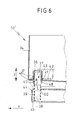
- Fig. 6 shows part of a side panel 34, approximately in the area the C-pillar of a motor vehicle.
- the viewing direction of the viewer of FIG. 5 corresponds approximately to the view of a viewer who moves from the motor vehicle fund to the Vehicle rear looks obliquely to the left.
- a backdrop 35 In the side panel 34 is a backdrop 35 after a Recess arranged, for example, towards the rear of the motor vehicle can rejuvenate.
- a receptacle 36 is located in the area of the backdrop receptacle 35 in the manner of a recess with a circular cylindrical cross section, for example educated. It serves to accommodate a fastening element 37, which is provided in the axial extension of a rod element 38.
- the rod element 38 is by means of a not shown Actuator along the double arrow Y, so in Vehicle transverse direction movable.
- Regarding the arrangement of a Actuator is based on the applicant's parallel patent application referenced on the same day (attorney docket number: 02.18136), its content is hereby completely included in the present patent application.
- Fig. 5 shows the fastener 37 in a release position, in the the fastener 37 is not yet immersed in the receptacle 36.
- Fig. 6 shows, however, the locked position of the fastener 37, in which this then with its end facing the outside of the vehicle into the Recording 36 immersed.
- the inside diameter of the Recording 36 (in direction X) is much larger than the outside diameter of the fastening element 37.
- the fastening element 37 would thus be loose, freely suspended within the receptacle 36 when that Fastening element 37 is in the locked position and no spacer 40 would be provided.
- Fastening element 37 is essentially conical in cross section Element 40 arranged. This has a circular cross section, for example on, and is in this way to the cross section of the fastener 37 adjusted.
- the cone element 40 is in the embodiment of the Figures 5 and 6 spacers in the sense of the invention.
- the cone element 40 is by a spring element 39, which with one end is supported on the housing side on a stop surface 45, of which Housing 44 away from the side cover 34, that is to say the fastening point, biased.
- the Strike plate 42 has a e.g. circular opening 43, into which itself the receptacle 36 extends.
- the peripheral edge of the opening 43 in the Strike plate 42 provides the crash-proof holding surface 41 which in the event of a crash, ensures that the resulting forces are absorbed are and a movement of the fastener 37 and thus the entire housing 44 in the vertical direction Z (Fig. 5) or in Direction X safely prevented.
- the fastener 37 By moving the fastener 37 from a release position 5 in a locked position Fig. 6 is on the one hand for this ensured that a crash-safe seating position of the fastening element 37 is achieved.
- the conical element 40 abuts when the Fastening element 37 in the course of the axial displacement of the Fastening element 37 with its outer peripheral surface 47 on one Edge area 48 of the receptacle 36 and, as it were, remains attached to it.
- the spring element 39 then tensioned, with the conical element 40 e.g. for a press fit of the Fastening element 37 can provide in the receptacle 36, but also how 6 shows such a press fit just prevented.
- the housing 44 is relative to the attachment point, ie relative to the Side cover 34, by the bias of the spring element 39 fixed against vibrations.
- the peculiarity is that not that Fastening element 37 clamped directly against the fastening point 34 is, but this is a separate element, in this case a Spacers 40, for biasing the housing relative to the Attachment point 34 provides.
- this also has Embodiment of Figures 5 and 6 a receptacle 36 for the Fastening element 37, which is of dimensions for the Fastening element 37 is actually too large, so the dimension Dimensions of the fastener 37 significantly exceed. This can result in very large tolerances of the vehicle body along the vehicle transverse direction as well as in or against the direction of travel X be balanced in a particularly elegant or safe way.
- the inclusion 36 according to FIGS. 5 and 6 is assigned a receiving space 50 which is clear is larger than the dimension of the fastener 37.
- Analog is at the embodiment of FIGS. 1 to 4 of the opening 15, which one likewise designate as a receptacle for the fastening element 17 can be assigned a receiving space 49, the dimension of Fastening element 17 significantly exceeds.
Landscapes
- Engineering & Computer Science (AREA)
- Mechanical Engineering (AREA)
- Transportation (AREA)
- Vibration Dampers (AREA)
- Connection Of Plates (AREA)
Abstract
Description
- Fig. 1
- schematisch, in teilgeschnittener Ansicht den Befestigungsbereich eines ersten Ausführungsbeispiels einer erfindungsgemäßen Kfz-Sicherheitseinrichtung mit in Löseposition befindlichem Befestigungselement,
- Fig. 2
- die Anordnung gemäß Fig. 1 mit in Sperrposition befindlichem Befestigungselement und einem in Vor-Montageposition befindlichem Gehäuse,
- Fig. 3
- eine Darstellung gemäß Fig. 2 mit in Montagepositon befindlichem Gehäuse,
- die Fig. 1a, 2a und 3a
- Schnittdarstellungen gemäß den Schnittlinien la-la, IIa-IIa, IIIa-IIIa durch ein fahrzeugseitig festgelegtes Laschenelement,
- Fig. 4
- in einer teilgeschnittenen Ansicht die Anordnung der Fig. 1 etwa Schnittlinie IV-IV in Fig. 1,
- Fig. 5
- schematisch in perspektivischer Ansicht ein zweites Ausführungsbeispiel der erfindungsgemäßen Kfz-Sicherheitseinrichtung, und
- Fig. 6
- eine Schnittdarstellung des Ausführungsbeispiels gemäß Fig. 5 mit in Sperrposition befindlichem Befestigungselement.
Claims (12)
- , Kfz-Sicherheitseinrichtung (10), wie Laderaumabdeckung, Trennnetz od. dgl., mit einer von einer Wickelwelle abziehbaren flexiblen Werkstoffbahn, die in einem Gehäuse (11, 44) gelagert ist, welches an wenigstens einer Befestigungsstelle (13, 34), z. B. fahrzeugseitig, mittels zumindest einem Befestigungselement (17, 37) lösbar festlegbar ist, wobei das Befestigungselement (17, 37) zwischen einer Sperrposition und einer Freigabeposition verlagerbar ist, dadurch gekennzeichnet, daß dem Befestigungselement eine Rückhaltevorrichtung mit einer fahrzeugseitig fest angeordneten und hochbelastbaren Haltefläche (16a, 16b, 41) zugeordnet ist, und daß ein Abstandhalter (19, 40) vorgesehen ist, der das in Sperrposition befindliche Befestigungselement (17, 37) von der Haltefläche beabstandet angeordnet hält.
- Kfz-Sicherheitseinrichtung nach Anspruch 1, dadurch gekennzeichnet, daß das Befestigungselement als axial verschiebbar an dem Gehäuse (11, 44) gelagerter Stift (17, 37) ausgebildet ist.
- Kfz-Sicherheitseinrichtung nach Anspruch 1 oder 2, dadurch gekennzeichnet, daß der Abstandshalter relativ zu dem Gehäuse verlagerbar, insbesondere axial verschiebbar an dem Gehäuse angeordnet ist.
- Kfz-Sicherheitseinrichtung nach einem der vorangegangenen Ansprüche, dadurch gekennzeichnet, daß der Abstandshalter relativ zu dem Befestigungselement verlagerbar, insbesondere axial verlagerbar angeordnet ist.
- Kfz-Sicherheitseinrichtung nach einem der vorangegangenen Ansprüche, dadurch gekennzeichnet, daß dem Befestigungselement eine fahrzeugseitig fest angeordnete Aufnahme (15, 36, 27b) zugeordnet ist.
- Kfz-Sicherheitseinrichtung nach Anspruch 5, dadurch gekennzeichnet, daß die Haltefläche (16a, 16b, 41) der Aufnahme (15, 36, 27b) zugeordnet ist.
- Kfz-Sicherheitseinrichtung nach Anspruch 5 oder 6, dadurch gekennzeichnet, daß die Aufnahme (15, 36, 27b) einen Aufnahmeraum (49, 50, 51) für das Befestigungselement aufweist, der die Dimensionen des Befestigungselementes wesentlich übersteigt.
- Kfz-Sicherheitseinrichtung nach einem der Ansprüche 5 bis 7, dadurch gekennzeichnet, daß dem Abstandshalter eine Führungsfläche (47) zugeordnet ist und insbesondere der Abstandshalter die Einführbewegung des Befestigungselementes in die Aufnahme hinein steuert.
- Kfz-Sicherheitseinrichtung nach einem der Ansprüche 5 bis 8, dadurch gekennzeichnet, daß die Haltefläche (16a, 16b) Bestandteil einer Aufnahme (15) für das Befestigungselement (17) ist.
- Kfz-Sicherheitseinrichtung nach einem der vorangegangenen Ansprüche, dadurch gekennzeichnet, daß die Haltefläche (41) Bestandteil einer Blechkonstruktion (42) ist, insbesondere einer fahrzeugseitigen Karosserie-Rahmenstruktur.
- Kfz-Sicherheitseinrichtung nach einem der vorangegangenen Ansprüche, dadurch gekennzeichnet, daß die Haltefläche (41) von einer Kfz-Innenverkleidung (34) verdeckt ist.
- Kfz-Sicherheitseinrichtung nach einem der vorangegangenen Ansprüche, dadurch gekennzeichnet, daß dem Abstandshalter (19, 40) wenigstens ein Federelement (20, 39) zugeordnet ist.
Applications Claiming Priority (2)
| Application Number | Priority Date | Filing Date | Title |
|---|---|---|---|
| DE10218631A DE10218631C1 (de) | 2002-04-25 | 2002-04-25 | Kfz-Sicherheitseinrichtung, wie Laderaumabdeckung, Trennnetz od. dgl. |
| DE10218631 | 2002-04-25 |
Publications (2)
| Publication Number | Publication Date |
|---|---|
| EP1356990A1 true EP1356990A1 (de) | 2003-10-29 |
| EP1356990B1 EP1356990B1 (de) | 2005-01-12 |
Family
ID=7714435
Family Applications (1)
| Application Number | Title | Priority Date | Filing Date |
|---|---|---|---|
| EP03004795A Expired - Lifetime EP1356990B1 (de) | 2002-04-25 | 2003-03-05 | Kfz-Sicherheitseinrichtung, wie Laderaumabdeckung, Trennnetz od. dgl. |
Country Status (2)
| Country | Link |
|---|---|
| EP (1) | EP1356990B1 (de) |
| DE (2) | DE10218631C1 (de) |
Cited By (1)
| Publication number | Priority date | Publication date | Assignee | Title |
|---|---|---|---|---|
| DE102007038113A1 (de) * | 2007-08-02 | 2009-02-05 | Bos Gmbh & Co. Kg | Laderaumabdeckung für ein Kraftfahrzeug |
Families Citing this family (2)
| Publication number | Priority date | Publication date | Assignee | Title |
|---|---|---|---|---|
| FR2993218A1 (fr) * | 2012-07-10 | 2014-01-17 | Cera | Systeme de recouvrement des bagages d'un vehicule automobile |
| US9718427B2 (en) * | 2013-07-19 | 2017-08-01 | Shield Restraint Sytems, Inc. | Latch device and anchor with swivel coupling |
Citations (6)
| Publication number | Priority date | Publication date | Assignee | Title |
|---|---|---|---|---|
| US5618077A (en) * | 1994-02-19 | 1997-04-08 | Baumeister & Ostler Gmbh & Co. | Roller cover for station wagons |
| US5961172A (en) * | 1996-05-24 | 1999-10-05 | Baumeister & Ostler Gmbh & Co. | Cargo space covering for a motor vehicle |
| US6125908A (en) * | 1997-08-20 | 2000-10-03 | Bos Gmbh & Co. Kg | Rolling cover for use in covering items stored in a vehicle storage area |
| DE10205156A1 (de) | 2002-01-07 | 2003-07-24 | Holger Hofmann | Gerät und Verfahren zum Bestimmen des Wassergehalts von Feststoffen |
| DE10205154A1 (de) | 2002-02-07 | 2003-08-28 | Butz Peter Verwaltung | Kfz-Sicherheitseinrichtung, wie Laderaumabdeckung, Sicherheitsnetz, Sonnenrollo od.dgl. |
| DE10205155A1 (de) | 2002-02-07 | 2003-08-28 | Butz Peter Verwaltung | Kfz-Sicherheitseinrichtung, wie Laderaumabdeckung, Sicherheitsnetz oder dergleichen |
-
2002
- 2002-04-25 DE DE10218631A patent/DE10218631C1/de not_active Expired - Fee Related
-
2003
- 2003-03-05 EP EP03004795A patent/EP1356990B1/de not_active Expired - Lifetime
- 2003-03-05 DE DE50300243T patent/DE50300243D1/de not_active Expired - Lifetime
Patent Citations (6)
| Publication number | Priority date | Publication date | Assignee | Title |
|---|---|---|---|---|
| US5618077A (en) * | 1994-02-19 | 1997-04-08 | Baumeister & Ostler Gmbh & Co. | Roller cover for station wagons |
| US5961172A (en) * | 1996-05-24 | 1999-10-05 | Baumeister & Ostler Gmbh & Co. | Cargo space covering for a motor vehicle |
| US6125908A (en) * | 1997-08-20 | 2000-10-03 | Bos Gmbh & Co. Kg | Rolling cover for use in covering items stored in a vehicle storage area |
| DE10205156A1 (de) | 2002-01-07 | 2003-07-24 | Holger Hofmann | Gerät und Verfahren zum Bestimmen des Wassergehalts von Feststoffen |
| DE10205154A1 (de) | 2002-02-07 | 2003-08-28 | Butz Peter Verwaltung | Kfz-Sicherheitseinrichtung, wie Laderaumabdeckung, Sicherheitsnetz, Sonnenrollo od.dgl. |
| DE10205155A1 (de) | 2002-02-07 | 2003-08-28 | Butz Peter Verwaltung | Kfz-Sicherheitseinrichtung, wie Laderaumabdeckung, Sicherheitsnetz oder dergleichen |
Cited By (2)
| Publication number | Priority date | Publication date | Assignee | Title |
|---|---|---|---|---|
| DE102007038113A1 (de) * | 2007-08-02 | 2009-02-05 | Bos Gmbh & Co. Kg | Laderaumabdeckung für ein Kraftfahrzeug |
| DE102007038113B4 (de) * | 2007-08-02 | 2009-07-23 | Bos Gmbh & Co. Kg | Laderaumabdeckung für ein Kraftfahrzeug |
Also Published As
| Publication number | Publication date |
|---|---|
| EP1356990B1 (de) | 2005-01-12 |
| DE50300243D1 (de) | 2005-02-17 |
| DE10218631C1 (de) | 2003-05-15 |
Similar Documents
| Publication | Publication Date | Title |
|---|---|---|
| EP1059200A2 (de) | Scheinwerfer | |
| DE10341060B4 (de) | Fahrzeugsonnenblende | |
| DE102007005517A1 (de) | Überrollschutzsystem für Kraftfahrzeuge mit einem aktiv aufstellbaren Überrollkörper | |
| EP0916552B1 (de) | Ausfahrbarer Überrollbügel für Kraftfahrzeuge | |
| EP0697307B1 (de) | Vorrichtung zum Verriegeln von geteilt klappbaren Rückenlehnen an Kraftfahrzeugrücksitzen | |
| DE4000904C2 (de) | Fahrzeugkarosserie mit einem einen Deckel aufweisenden Anbau | |
| EP1356991B1 (de) | Kfz-Sicherheitseinrichtung, wie Laderaumabdeckung, Trennnetz od.dgl. | |
| DE10205155B4 (de) | Kfz-Sicherheitseinrichtung, wie Laderaumabdeckung, Sicherheitsnetz oder dergleichen | |
| DE60207179T2 (de) | Airbagmodul | |
| EP0618110A1 (de) | Armaturentafel mit Beifahrer-Airbag | |
| EP1216884B1 (de) | Vorrichtung zur Aufnahme eines Laderaumabdeckrollos oder Sicherheitsnetzes | |
| EP1356990B1 (de) | Kfz-Sicherheitseinrichtung, wie Laderaumabdeckung, Trennnetz od. dgl. | |
| EP0893306B1 (de) | Kofferraum-Einrichtung für den Einbau in Kraftfahrzeuge, insbesondere für den sitzlehnenseitigen Einbau in Personenkraftwagen | |
| DE10205154B4 (de) | Kfz-Sicherheitseinrichtung, wie Laderaumabdeckung, Sicherheitsnetz, Sonnenrollo od.dgl. | |
| DE102006028664A1 (de) | Überrollschutzsystem für ein Kraftfahrzeug | |
| EP1382489A1 (de) | Schutzvorrichtung für den Laderaum eines Kraftfahrzeuges | |
| DE2915333A1 (de) | Festhaltevorrichtung an autoradiogeraeten | |
| EP2882614B1 (de) | Einrichtung zur anordnung einer warnwesteneinrichtung an einer seitentür eines kraftwagens | |
| EP2060422B1 (de) | Rolloeinrichtung für ein Kraftfahrzeug | |
| DE102008055907A1 (de) | Befestigungssystem für Funktionselemente in einem Kraftfahrzeug | |
| DE10300505B4 (de) | Kfz-Sicherheitseinrichtung, insbesondere Kfz-Trennnetz | |
| DE10222050B4 (de) | Einhängevorrichtung für einen Bolzen mit Kopf an einem Fahrzeug | |
| DE102007061222A1 (de) | Kraftfahrzeugsitz mit einer von unten an dem Kraftfahrzeugsitz befestigen Aufnahmeeinrichtung | |
| DE202015104721U1 (de) | Gepäckhaltevorrichtung und Motorrad mit einer solchen | |
| DE102007015075B4 (de) | Befestigungseinrichtung für Funktionseinrichtungen in Fahrzeugen |
Legal Events
| Date | Code | Title | Description |
|---|---|---|---|
| PUAI | Public reference made under article 153(3) epc to a published international application that has entered the european phase |
Free format text: ORIGINAL CODE: 0009012 |
|
| AK | Designated contracting states |
Kind code of ref document: A1 Designated state(s): AT BE BG CH CY CZ DE DK EE ES FI FR GB GR HU IE IT LI LU MC NL PT RO SE SI SK TR |
|
| AX | Request for extension of the european patent |
Extension state: AL LT LV MK |
|
| 17P | Request for examination filed |
Effective date: 20040407 |
|
| GRAP | Despatch of communication of intention to grant a patent |
Free format text: ORIGINAL CODE: EPIDOSNIGR1 |
|
| AKX | Designation fees paid |
Designated state(s): DE FR GB SE |
|
| RAP1 | Party data changed (applicant data changed or rights of an application transferred) |
Owner name: BOS GMBH & CO. KG |
|
| GRAS | Grant fee paid |
Free format text: ORIGINAL CODE: EPIDOSNIGR3 |
|
| GRAA | (expected) grant |
Free format text: ORIGINAL CODE: 0009210 |
|
| AK | Designated contracting states |
Kind code of ref document: B1 Designated state(s): DE FR GB SE |
|
| REG | Reference to a national code |
Ref country code: GB Ref legal event code: FG4D Free format text: NOT ENGLISH |
|
| REF | Corresponds to: |
Ref document number: 50300243 Country of ref document: DE Date of ref document: 20050217 Kind code of ref document: P |
|
| REG | Reference to a national code |
Ref country code: IE Ref legal event code: FG4D Free format text: GERMAN |
|
| REG | Reference to a national code |
Ref country code: SE Ref legal event code: TRGR |
|
| GBT | Gb: translation of ep patent filed (gb section 77(6)(a)/1977) |
Effective date: 20050412 |
|
| ET | Fr: translation filed | ||
| PLBE | No opposition filed within time limit |
Free format text: ORIGINAL CODE: 0009261 |
|
| STAA | Information on the status of an ep patent application or granted ep patent |
Free format text: STATUS: NO OPPOSITION FILED WITHIN TIME LIMIT |
|
| 26N | No opposition filed |
Effective date: 20051013 |
|
| PGFP | Annual fee paid to national office [announced via postgrant information from national office to epo] |
Ref country code: GB Payment date: 20080318 Year of fee payment: 6 Ref country code: SE Payment date: 20080320 Year of fee payment: 6 |
|
| PGFP | Annual fee paid to national office [announced via postgrant information from national office to epo] |
Ref country code: FR Payment date: 20080314 Year of fee payment: 6 |
|
| EUG | Se: european patent has lapsed | ||
| GBPC | Gb: european patent ceased through non-payment of renewal fee |
Effective date: 20090305 |
|
| REG | Reference to a national code |
Ref country code: FR Ref legal event code: ST Effective date: 20091130 |
|
| PG25 | Lapsed in a contracting state [announced via postgrant information from national office to epo] |
Ref country code: FR Free format text: LAPSE BECAUSE OF NON-PAYMENT OF DUE FEES Effective date: 20091123 Ref country code: GB Free format text: LAPSE BECAUSE OF NON-PAYMENT OF DUE FEES Effective date: 20090305 |
|
| PG25 | Lapsed in a contracting state [announced via postgrant information from national office to epo] |
Ref country code: SE Free format text: LAPSE BECAUSE OF NON-PAYMENT OF DUE FEES Effective date: 20090306 |
|
| PGFP | Annual fee paid to national office [announced via postgrant information from national office to epo] |
Ref country code: DE Payment date: 20130326 Year of fee payment: 11 |
|
| REG | Reference to a national code |
Ref country code: DE Ref legal event code: R119 Ref document number: 50300243 Country of ref document: DE |
|
| REG | Reference to a national code |
Ref country code: DE Ref legal event code: R119 Ref document number: 50300243 Country of ref document: DE Effective date: 20141001 |
|
| PG25 | Lapsed in a contracting state [announced via postgrant information from national office to epo] |
Ref country code: DE Free format text: LAPSE BECAUSE OF NON-PAYMENT OF DUE FEES Effective date: 20141001 |