EP1356907A2 - Ausrichtungswerkzeug für Korken - Google Patents
Ausrichtungswerkzeug für Korken Download PDFInfo
- Publication number
- EP1356907A2 EP1356907A2 EP03076112A EP03076112A EP1356907A2 EP 1356907 A2 EP1356907 A2 EP 1356907A2 EP 03076112 A EP03076112 A EP 03076112A EP 03076112 A EP03076112 A EP 03076112A EP 1356907 A2 EP1356907 A2 EP 1356907A2
- Authority
- EP
- European Patent Office
- Prior art keywords
- stoppers
- axis
- trueing
- circular blade
- machine according
- Prior art date
- Legal status (The legal status is an assumption and is not a legal conclusion. Google has not performed a legal analysis and makes no representation as to the accuracy of the status listed.)
- Withdrawn
Links
- 239000007799 cork Substances 0.000 title claims description 21
- 230000000712 assembly Effects 0.000 claims abstract description 4
- 238000000429 assembly Methods 0.000 claims abstract description 4
- 230000002093 peripheral effect Effects 0.000 claims description 5
- ZOKXTWBITQBERF-UHFFFAOYSA-N Molybdenum Chemical compound [Mo] ZOKXTWBITQBERF-UHFFFAOYSA-N 0.000 claims description 2
- 239000011230 binding agent Substances 0.000 claims description 2
- 239000010941 cobalt Substances 0.000 claims description 2
- 229910017052 cobalt Inorganic materials 0.000 claims description 2
- GUTLYIVDDKVIGB-UHFFFAOYSA-N cobalt atom Chemical compound [Co] GUTLYIVDDKVIGB-UHFFFAOYSA-N 0.000 claims description 2
- 230000005484 gravity Effects 0.000 claims description 2
- 229910052750 molybdenum Inorganic materials 0.000 claims description 2
- 239000011733 molybdenum Substances 0.000 claims description 2
- 229910052715 tantalum Inorganic materials 0.000 claims description 2
- -1 tantalum carbides Chemical class 0.000 claims description 2
- WFKWXMTUELFFGS-UHFFFAOYSA-N tungsten Chemical compound [W] WFKWXMTUELFFGS-UHFFFAOYSA-N 0.000 claims description 2
- 229910052721 tungsten Inorganic materials 0.000 claims description 2
- 239000010937 tungsten Substances 0.000 claims description 2
- 238000004519 manufacturing process Methods 0.000 description 5
- 239000000463 material Substances 0.000 description 5
- 239000006061 abrasive grain Substances 0.000 description 2
- 239000000428 dust Substances 0.000 description 2
- 210000003739 neck Anatomy 0.000 description 2
- 229910000831 Steel Inorganic materials 0.000 description 1
- 239000003082 abrasive agent Substances 0.000 description 1
- 239000000853 adhesive Substances 0.000 description 1
- 238000004026 adhesive bonding Methods 0.000 description 1
- 230000001070 adhesive effect Effects 0.000 description 1
- 230000004323 axial length Effects 0.000 description 1
- 239000002131 composite material Substances 0.000 description 1
- 210000005069 ears Anatomy 0.000 description 1
- 238000001125 extrusion Methods 0.000 description 1
- 239000011521 glass Substances 0.000 description 1
- 229910052751 metal Inorganic materials 0.000 description 1
- 239000002184 metal Substances 0.000 description 1
- 239000011265 semifinished product Substances 0.000 description 1
- 239000010959 steel Substances 0.000 description 1
- 238000006467 substitution reaction Methods 0.000 description 1
- 230000001131 transforming effect Effects 0.000 description 1
- 238000011144 upstream manufacturing Methods 0.000 description 1
Images



Classifications
-
- B—PERFORMING OPERATIONS; TRANSPORTING
- B26—HAND CUTTING TOOLS; CUTTING; SEVERING
- B26D—CUTTING; DETAILS COMMON TO MACHINES FOR PERFORATING, PUNCHING, CUTTING-OUT, STAMPING-OUT OR SEVERING
- B26D3/00—Cutting work characterised by the nature of the cut made; Apparatus therefor
- B26D3/28—Splitting layers from work; Mutually separating layers by cutting
-
- B—PERFORMING OPERATIONS; TRANSPORTING
- B27—WORKING OR PRESERVING WOOD OR SIMILAR MATERIAL; NAILING OR STAPLING MACHINES IN GENERAL
- B27J—MECHANICAL WORKING OF CANE, CORK, OR SIMILAR MATERIALS
- B27J5/00—Mechanical working of cork
Definitions
- the present invention relates to a trueing machine for cork stoppers according to the preamble of claim 1.
- the invention has been conceived in its application to the trueing of agglomerated cork stoppers and of glued stoppers, but is also applicable to the trueing of natural cork stoppers.
- Agglomerated cork stoppers are cylindrical bodies of a material constituted by milled cork grains bonded by a suitable adhesive.
- Glued stoppers are composite stoppers constituted by a main cylindrical component or body of agglomerated cork, which has at least one disc of valuable natural cork glued to at least one of its ends.
- a machine known from a long time, account of which is given in the preamble of claim 1, is similar to a lathe in which every single stopper, while it is rotated around its axis, is turned between centres by means of a circular blade whose peripheral cutting edge tangentially engages the periphery of the stopper.
- a continuous machine which avoids both the aforesaid idle times and the aforesaid pollution due to abrasive, but which can be used only for the trueing of cylindrical agglomerated cork bars, before these bars are severed into sections each having the length of a finished stopper.
- the known continuous machine in which the tool is still a circular blade and in which the bar is fed in the axial direction, solves the problem to drive the piece into rotation, the rotation being obtained by means of rollers.
- the main object of the invention is to provide a trueing machine for cork stoppers which has the advantageous characteristics of the aforesaid continuous machine, but which can be used for the continuous trueing of single stoppers.
- a machine according to the invention allows to obtain, through the trueing station, a continuous flow of stoppers which are driven into rotation one after the other around their axis.
- Each stopper which reaches the trueing station from the feeding conduit is first seized and centered by the set of three rotary members of the first assembly, which is immediately upstream of the circular blade, and is driven into rotation around its axis and fed onwards by the corresponding driving wheel.
- the rotating stopper Once the rotating stopper has been seized and centered, it is engaged by the circular blade which removes a layer of a predetermined thickness all over its length. The trued portion is then introduced between the rotary members of the set of three members of the second assembly, which is immediately downstream of the blade.
- the stopper Since the adjustment of the rotary members of the second assembly, which takes account of the reduction of diameter of the stopper due to the trueing, the stopper remains centered on the same axis as before and continues to be driven into rotation and to be fed onwards, this time by the driving wheel of the second assembly.
- the machine shown comprises a bench B which supports a fixed horizontal table 10 and a structure which defines a trueing station, generally indicated 12.
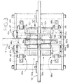
- a tubular feeding conduit 14 which can be better seen in figures 3 and 5, extends above the table 10 and comes from a feeder of raw stoppers to be trued, indicated S1, for example from a vibrating hopper (not shown).
- the feeding conduit 14 and the axis of the stoppers S1, indicated Z in figure 5, are vertical and the feeding of the stoppers in the conduit 14 takes place by gravity.
- the conduit 14 has a lower end which opens onto an upper region of the trueing station 12.
- a circular blade 16 located in the trueing station 12 is carried and rotated by the shaft of an electric motor 18.
- the cutting edge of the blade 16 engages the peripheral surface of the successive raw stoppers S1 which come down from the conduit 14 in order to remove a layer of a predetermined thickness from the stoppers, as shown for the stopper S2, transforming them into finished stoppers, indicated S3.
- stoppers S3 fall into an underlying conduit, not shown, which leads to a receptacle or a conveyor belt.
- the axis of the circular blade 16, indicated A in figures 1 and 2 is askew with respect to the axis of the successive stoppers S1, S2, S3, in order to obtain that, while the stoppers are fed downwards, a layer of cork is removed from their surface in the form of a helical chip, which may be discontinuous in the most frequent case of the trueing of agglomerated stoppers.
- the circular blade 16 is provided with a peripheral cutting portion of a sintered agglomerate of tungsten, molybdenum or tantalum carbides, with cobalt as a binder, such as Widia®.
- the abrasive discs and tapes according to the prior art produced stoppers of agglomerated cork with ground surfaces which showed craters with "torn out” edges which were anything but suitable to guarantee a perfectly tight seal of the stoppers in the necks of the bottles.
- the electric motor 18 of the circular blade 16 is carried by a slide 22 which can be micrometrically moved towards the stoppers S1, S2, S3 and in the opposite direction by means of a handwheel 24 for adjusting the cutting depth of the blade 16.
- a platform 26 is interposed between the slide 22 and the motor 18 and can be adjusted by means of a handwheel 28 in order to bring back the circular blade 16 to the tangent cutting position after each sharpening.
- the trueing station 12 comprises a pair of assemblies for driving and centering the stoppers.
- a first assembly or upper assembly, generally indicated 30a, is located immediately before the circular blade 16; a second assembly or lower assembly, generally indicated 30b, is located immediately after the circular blade 16.
- the parts of the two assemblies, the upper one 30a and the lower one 30b, are identical or substantially such, in the description which follows and in the drawings they are indicated by the same reference numerals followed by the letter a for the upper assembly 30a and by the letter b for the lower assembly 30b.
- the upper assembly 30a is located above and the lower assembly 30b is located under the table 10.
- Each assembly 30a, 30b includes a respective set of three rotary members which engage the stoppers S1, S2, S3, respectively, according to generatrices arranged like the vertexes of a triangle.
- One of these rotary members, 32a and 32b, respectively, is a motorized driving wheel, having an axis which is inclined with respect to the axis Z of the stoppers S1, S2, S3.
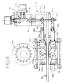
- Each driving wheel 32a, 32b drives into rotation the raw stoppers S1 and the finished stoppers S3, respectively, as well as a stopper S2 which is being trued, and is rotated by a respective asynchronous electric motor 34a, 34b (figure 2) in such a direction as to feed the stoppers along their common axis Z.
- the distance between the two driving wheels 32a, 32b in the direction Z is chosen smaller than the length of the stoppers, so as to make sure that a stopper S1 to be trued, a stopper S2 which is being trued, and a stopper S3 which has just been trued are always engaged by the periphery of one of these wheels.
- Each driving wheel 32a, 32b is preferably provided with a rim of a slightly abrasive material in order to ensure the revolving friction for driving the stoppers S1, S2, S3 both into rotation and translation.
- the other two rotary members of each set of three are a pair of idle, cylindrical and smooth, pressure rollers 36a, 36b, respectively, of small diameter, also visible in figure 1.
- the axes of all the pressure rollers 36a, 36b are parallel to the axis Z of the stoppers S1, S2, S3.
- the axial length, in the direction Z, of the rollers 36a, 36b is substantially equal to the axial height of the respective driving wheel 30a, 30b, so as to make sure that a stopper S1 to be trued, a stopper S2 which is being trued, and a stopper S3 which has just been trued are always engaged also by the pressure rollers 36a and/or 36b.
- the three rotary members 32a, 36a and 32b, 36b of each assembly 30a, 30b are interconnected by a respective self-centering linkage, generally indicated 38a for the upper linkage and 38b for the lower linkage in figure 3.
- Each self-centering linkage 38a, 38b is provided with adjusting means which are so arranged that in the trueing station 12 the axis Z of each stopper S1, S2, S3 remains the same before, during and after the trueing.
- the motorized driving wheel 32a, 32b of each assembly 30a, 30b is carried by a respective slide 40a, 40b (figure 2) whose position is adjustable, independently from the other slide, in a horizontal direction X, perpendicular to the axis Z of the stoppers S1, S2, S3.
- a device for adjusting the position of the slides 40a, 40b will be described more below.
- Each self-centering linkage 38a, 38b preferably includes (figures 1, 2 and 3) a respective pair of rocking levers 42a, 42b each of which is fulcrumed at 46 on the table 10 around a respective fixed axis which is parallel to the axis Z of the stoppers S1, S2, S3.
- One arm 44a, 44b of each rocking lever 42a, 42b is linked to the respective slide 40a, 40b by a respective connecting rod 48a, 48b of adjustable length, while the other arm 46a, 46b of the lever 42a, 42b carries the respective pressure roller 36a, 36b.
- the levers 42a, 42b of each linkage 38a, 38b are specularly arranged with respect to a median plane containing the axis Z of the stoppers S1, S2, S3 and passing through the centre of the corresponding driving wheel 32a, 32b.
- a respective thrust regulator for the respective driving wheel 32a, 32b is associated to the slide 40a, 40b of each assembly 30a, 30b.
- the two thrust regulators are independent from each other.
- Each thrust regulator 50a, 50b includes a respective pneumatic actuator 52a, 52b with a respective piston rod 54a, 54b which is connected to the corresponding slide 40a, 40b in the manner which will be described below, and which biases the slide towards the stoppers S1, S3.
- the two actuators 52a, 52b are fed with compressed air through a common pressure regulator, diagrammatically shown in dotted lines at 55.
- each actuator 52a, 52b has associated thereto a respective micrometric adjustment device for adjusting the end position of the corresponding slide 40a, 40b according to the diameter of the raw stoppers S1 and the finished stoppers S3, respectively.
- Figure 2 shows respective handwheels, indicated 56a, 56b, for the micrometric adjustment of the end position of the upper slide 40a and the lower slide 40b, respectively.
- Each handwheel 56a, 56b is fast with a respective toothed crown 57a, 57b having an inner toothing in mesh with the outer toothing of a respective tubular pinion 58a, 58b.
- Each pinion 58a, 58b has an inner thread having the function of a nut, which is in engagement with a corresponding threaded rear section of the rod 54a, 54b of a respective actuator 52a, 52b.
- the two driving wheels 32a, 32b have the same diameter, if they were rotated at the same angular speed the upper wheel 32a would rotate the raw stoppers S1 at an angular speed lower than that at which the lower wheel 32b rotates the stoppers S3, whose diameter has been reduced by the trueing.
- each driving wheel 32a, 32b is driven by the respective asynchronous electric motor 34a, 34b through a respective 90° reduction gear 60a, 60b and from an electrical circuit (not shown) which allows the speeds of the two asynchronous motors 34a, 34b to be automatically adjusted in such a manner as to impart to all the stoppers S1, S2, S3 the same speed of rotation before, during and after the trueing.
- the inclination of the driving wheels 32a, 32b is adjustable in order to allow to regulate the feed rate of the stoppers S1, S2, S3 according to the requirements.
- Each slide 40a, 40b has a pair of brackets affixed thereto, 62a, 62b, respectively, each of which pairs is supported by a respective horizontal, revolving and sliding shaft 64a, 64b which constitutes an extension of a respective piston rod 54a, 54b.
- Each of the slides 40a, 40b is provided with a respective orthogonal pivot pin 66a, 66b.
- the table 10 carries a lateral turret 68 in which a vertical nut 70 is fixed, which is in engagement with a vertical threaded shaft 72.
- the micrometric rotation of the nut 70 can be obtained, through a bevel gear pair 74, from a handwheel 76.
- Each pivot pin 66a, 66b is connected to the threaded shaft 72 through a respective telescopic connecting rod 78a, 78b.
- each telescopic connecting rod 78a, 78b is articulated to the respective pivot pin 66a, 66b by means of a bushing 80a, 80b, preferably of the ball-type, and its other end is coupled to the threaded shaft 72 by means of a respective ear 82a, 82b.
- Each ear 82a, 82b is imprisoned between two nuts, 84a and 84b, respectively, which prevent them from sliding along the shaft 72.
- the adjusting system of figure 4 allows to adjust in unison the inclination of the two driving wheels 32a, 32b from the handwheel 76; by rotating the handwheel 76 by hand in one direction or the other, the two bushings 80a, 80b and the two pivot pins 66a, 66b are raised and lowered jointly, whereby the respective slides 40a, 40b and the two driving wheels 32a, 32b are rotated in unison, through the respective pivot pins 66a, 66b, according to the double arrows G of figures 4 an 6.
Landscapes
- Life Sciences & Earth Sciences (AREA)
- Forests & Forestry (AREA)
- Engineering & Computer Science (AREA)
- Mechanical Engineering (AREA)
- Finish Polishing, Edge Sharpening, And Grinding By Specific Grinding Devices (AREA)
Applications Claiming Priority (2)
| Application Number | Priority Date | Filing Date | Title |
|---|---|---|---|
| IT2002TO000345A ITTO20020345A1 (it) | 2002-04-22 | 2002-04-22 | Macchina per la rettifica di tappi di sughero. |
| ITTO20020345 | 2002-04-22 |
Publications (1)
| Publication Number | Publication Date |
|---|---|
| EP1356907A2 true EP1356907A2 (de) | 2003-10-29 |
Family
ID=27639021
Family Applications (1)
| Application Number | Title | Priority Date | Filing Date |
|---|---|---|---|
| EP03076112A Withdrawn EP1356907A2 (de) | 2002-04-22 | 2003-04-15 | Ausrichtungswerkzeug für Korken |
Country Status (2)
| Country | Link |
|---|---|
| EP (1) | EP1356907A2 (de) |
| IT (1) | ITTO20020345A1 (de) |
Cited By (3)
| Publication number | Priority date | Publication date | Assignee | Title |
|---|---|---|---|---|
| ES2302486A1 (es) * | 2008-02-21 | 2008-07-01 | Jose Luis Godoy Varo | Metodo y aparato para fabricacion de tapones multicapa de corcho natural y tapon multicapa de corcho natural. |
| CN101544007A (zh) * | 2009-02-20 | 2009-09-30 | 宋树建 | 一种木塞加工设备 |
| CN109397428A (zh) * | 2018-10-15 | 2019-03-01 | 尹晓利 | 一种竹伞骨削尖设备 |
-
2002
- 2002-04-22 IT IT2002TO000345A patent/ITTO20020345A1/it unknown
-
2003
- 2003-04-15 EP EP03076112A patent/EP1356907A2/de not_active Withdrawn
Cited By (5)
| Publication number | Priority date | Publication date | Assignee | Title |
|---|---|---|---|---|
| ES2302486A1 (es) * | 2008-02-21 | 2008-07-01 | Jose Luis Godoy Varo | Metodo y aparato para fabricacion de tapones multicapa de corcho natural y tapon multicapa de corcho natural. |
| ES2302486B1 (es) * | 2008-02-21 | 2009-07-27 | Jose Luis Godoy Varo | Metodo y aparato para fabricacion de tapones multicapa de corcho natural y tapon multicapa de corcho natural. |
| CN101544007A (zh) * | 2009-02-20 | 2009-09-30 | 宋树建 | 一种木塞加工设备 |
| CN101544007B (zh) * | 2009-02-20 | 2014-02-26 | 宋树建 | 一种木塞加工设备 |
| CN109397428A (zh) * | 2018-10-15 | 2019-03-01 | 尹晓利 | 一种竹伞骨削尖设备 |
Also Published As
| Publication number | Publication date |
|---|---|
| ITTO20020345A0 (it) | 2002-04-22 |
| ITTO20020345A1 (it) | 2003-10-22 |
Similar Documents
| Publication | Publication Date | Title |
|---|---|---|
| US5040342A (en) | Method and apparatus for processing glass sheets | |
| US6609956B2 (en) | Method and machine for grinding coated sheets of glass | |
| CN102458759B (zh) | 磨削支撑装置 | |
| US5079876A (en) | Method and installation for processing glass plates | |
| CN102107453B (zh) | 五轴数控刻楦机 | |
| CN217046820U (zh) | 一种斜边自动封边机 | |
| CN101104246B (zh) | 磨边机 | |
| CN219131175U (zh) | 一种用于激光切割机的自动送料装置 | |
| CN107253293A (zh) | 一种全自动直边倒角抛光机 | |
| CN116000323A (zh) | 一种附带姿态调整功能的偏心轴加工设备 | |
| EP1356907A2 (de) | Ausrichtungswerkzeug für Korken | |
| CN115301961A (zh) | 一种用于医疗器械加工的长轴加工辅助装置 | |
| CN202878032U (zh) | 全自动磨削流水线 | |
| CN112549723A (zh) | 一种多排自动转贴复合工艺模切机 | |
| CN1216721C (zh) | 用于制造有齿传送带的模子的方法和装置 | |
| CN201089101Y (zh) | 磨边机 | |
| CN104924207B (zh) | 一种高速双头数控刃磨机主轴装置及刃磨方法 | |
| CN206105561U (zh) | 丝杠加工专用磨床 | |
| CN213562999U (zh) | 一种板材修边设备 | |
| CN214491979U (zh) | 一种多排自动转贴复合工艺模切机 | |
| CN210911333U (zh) | 一种糊盒机的糊口加固装置 | |
| CN101456147B (zh) | 一种用于立车圆导轨的磨削加工装置 | |
| US4559987A (en) | Veneer lathe | |
| CN105058199B (zh) | 一种人工晶体材料碗形整流罩专用加工设备 | |
| CN219582368U (zh) | 一种数控外圆磨削抛光机 |
Legal Events
| Date | Code | Title | Description |
|---|---|---|---|
| PUAI | Public reference made under article 153(3) epc to a published international application that has entered the european phase |
Free format text: ORIGINAL CODE: 0009012 |
|
| AK | Designated contracting states |
Kind code of ref document: A2 Designated state(s): AT BE BG CH CY CZ DE DK EE ES FI FR GB GR HU IE IT LI LU MC NL PT RO SE SI SK TR |
|
| AX | Request for extension of the european patent |
Extension state: AL LT LV MK |
|
| STAA | Information on the status of an ep patent application or granted ep patent |
Free format text: STATUS: THE APPLICATION IS DEEMED TO BE WITHDRAWN |
|
| 18D | Application deemed to be withdrawn |
Effective date: 20051102 |