EP1356487B1 - Thermisch auslösbarer schutzschalter - Google Patents
Thermisch auslösbarer schutzschalter Download PDFInfo
- Publication number
- EP1356487B1 EP1356487B1 EP02714106A EP02714106A EP1356487B1 EP 1356487 B1 EP1356487 B1 EP 1356487B1 EP 02714106 A EP02714106 A EP 02714106A EP 02714106 A EP02714106 A EP 02714106A EP 1356487 B1 EP1356487 B1 EP 1356487B1
- Authority
- EP
- European Patent Office
- Prior art keywords
- bimetallic
- functional
- support
- bimetallic strip
- limb
- Prior art date
- Legal status (The legal status is an assumption and is not a legal conclusion. Google has not performed a legal analysis and makes no representation as to the accuracy of the status listed.)
- Expired - Lifetime
Links
- 238000005452 bending Methods 0.000 claims description 12
- 230000006835 compression Effects 0.000 claims description 4
- 238000007906 compression Methods 0.000 claims description 4
- 238000010438 heat treatment Methods 0.000 claims description 4
- 230000001419 dependent effect Effects 0.000 description 2
- 238000011161 development Methods 0.000 description 2
- 230000018109 developmental process Effects 0.000 description 2
- 238000004519 manufacturing process Methods 0.000 description 2
- 239000000463 material Substances 0.000 description 2
- 238000005219 brazing Methods 0.000 description 1
- 230000007797 corrosion Effects 0.000 description 1
- 238000005260 corrosion Methods 0.000 description 1
- 230000000694 effects Effects 0.000 description 1
- 239000011810 insulating material Substances 0.000 description 1
- 230000001960 triggered effect Effects 0.000 description 1
- 238000003466 welding Methods 0.000 description 1
Images

Classifications
-
- H—ELECTRICITY
- H01—ELECTRIC ELEMENTS
- H01H—ELECTRIC SWITCHES; RELAYS; SELECTORS; EMERGENCY PROTECTIVE DEVICES
- H01H71/00—Details of the protective switches or relays covered by groups H01H73/00 - H01H83/00
- H01H71/10—Operating or release mechanisms
- H01H71/12—Automatic release mechanisms with or without manual release
- H01H71/14—Electrothermal mechanisms
- H01H71/16—Electrothermal mechanisms with bimetal element
- H01H71/162—Electrothermal mechanisms with bimetal element with compensation for ambient temperature
Definitions
- the invention relates to a thermally triggering circuit breaker with one of one Working bimetal held bimetallic.
- a thermally triggering circuit breaker with one of one Working bimetal held bimetallic.
- Known circuit breakers are preferably used in motor vehicles.
- the invention is therefore based on the object of a thermally triggering circuit breaker to create the largely independent of fluctuations in its ambient temperature has a constant tripping characteristic.
- the bimetal support and the connection contact electrically connected to it in one piece.
- This can be done by bending the connection contact from the with a Functional level identical to the housing level of the effective compensation bimetal Carry out the bimetal carrier.
- This forms the working bimetal and the compensation bimetal designed bimetal supports each with regard to their outer contour preferably right-angled component, one leg each with its Each end adjoins the outside in an easy-to-manufacture manner Way connected.
- An existing fixing hook can also be used Be part of the bimetal carrier designed as a compensation bimetal. This favors simple manufacture.
- connection contact as a bimetal does not prepare Fixing problems.
- the extension of the active side of the bimetallic contact directly on the wall of an insulating housing of the circuit breaker intercepts temperature tensions in the immediate vicinity.
- the bending movements of the working legs are in each case one of the working bimetal and the bimetal carrier effective as compensation bimetal limiting stop fixed to the housing is provided.
- the work leg of the bimetallic support limiting stop by appropriate housing positioning effective in the case of bimetallic heating. This ensures that the trigger function of the switch takes precedence over the compensation function of the bimetal support. This is one for the safe functioning of the circuit breaker important warranty.
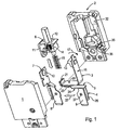
- the circuit breaker comprises a housing with two with their opening sides facing each other facing, made of insulating material housing halves 1, 2, which are the functional parts of the circuit breaker shielded from the outside. You give the circuit breaker in the assembly position the shape of a flat cuboid with approximately parallel to its outer surfaces running division level. This division level also largely lies the plane of movement of the functional parts encapsulated by the two housing halves 1, 2.
- the thermally tripping circuit breaker contains a working bimetal 3 and one Working bimetal 3, in particular housing-fixed, fixing bimetal carrier 4.
- the bimetal carrier 4 is a compensation bimetal which bends in the opposite direction to the working bimetal 3. Both bimetals 3, 4 are connected in series and the current flows through them. This corresponds to the design of the circuit breaker largely the subject of EP 0 450 366 B1 with the essential difference, however, that not only the working bimetal 3 but also the bimetal carrier 4 are bimetals.
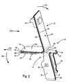
- the working bimetal 3. and the bimetal carrier 4 are thus connected to one another to form a bimetal unit 5.
- circuit breaker in addition to the bimetal unit 5 essential functional components are a contact bridge 6 and a fixed contact piece 7 with its plug connection 8. These functional parts are between the Housing halves 1,2 included.
- the current flow of the activated circuit breaker between the plug connector 8 of the fixed contact piece 7 and a one-piece with the bimetallic support 4 connecting or plug contact 9 of the bimetal unit 5 extends from the one with the plug connection 8 one-piece and fixed contact housing 10 via the angular contact bridge 6 to the working bimetal 3 and from there via the bimetal support 4 to the plug contact 9 and vice versa.
- the fixed contact 10 acts in a contacting manner on a vertical leg 11 of the angular contact bridge 6, the horizontal leg 12 with his Free end engages under a retaining lug 13 of the working bimetal 3 and thereby from one Swivel compression spring 14 and a trigger spring 15 permanently against the bottom of the Holding nose 13 is acted upon.
- the retaining lug 13 acts on the free end of the horizontal leg 12 of the Contact bridge 6 and holds this in the on position relative to the fixed contact 10 and the two springs acting on the contact bridge 6 in their opening direction 15.16 under compression.
- the working bimetal 3 heats up under current. Its working leg 16 bends clockwise 17 compared to the bimetallic support 4 fixed to the housing. The one at the end of the working leg 16 of the working bimetal 3 holding nose 13 is thereby retracted their application position opposite the contact bridge 6. As a result, the contact bridge 6 with relaxation of the compression springs 14, 15 in its open position pivoted. The contact between the bimetallic unit 5 and the fixed contact piece 7 is torn open.
- the pivoting out of his working leg caused by the heating of the working bimetal 3 16 clockwise 17 is a result of the fact that an active layer 18 the inside and a passive layer 19 the outside of the substantially form right-angled working bimetal 3.
- the Working leg 16 aligned vertically.
- the other, horizontal leg of the one-piece, working bimetal 3 bent at right angles is the fixing leg 20.
- the fixing leg 20 is with its free end 21 on the same direction (direction 22) protruding and horizontally oriented free end 23 of a horizontal connecting arm or Work leg 24 of the bimetallic support 4 fixed.
- the bimetal support 4 is also a bimetal. It is in one piece with the plug contact 9 and with a fixing hook 25 for fixing the circuit breaker in a (not shown) Socket.
- the fixing hook 25 is in the mounting position of the circuit breaker - Just like the two plug contacts 8 and 9 - from the insulating housing (housing halves 1,2) to the outside.
- the bimetal support 4 is fixed to the housing in the mounting position fixed or clamped between the two housing halves 1, 2.
- An active layer 26 of the bimetallic working leg 24 of the bimetallic carrier 4 is facing the fixing leg 20 of the working bimetal 3.
- a passive layer 27 of the Bimetal support 4 lies in the area of the working leg 24 on that of the fixing leg 20 of the working bimetal 3 side facing away.
- the self-acting bimetallic carrier bimetallic carrier 4 which acts as a compensation bimetal 4 is a sheet-like laminate with the level of the fixing leg 20 of the working bimetal 3 approximately parallel layer plane.
- the connection contact 9 and the fixing hook 25 of the bimetal support 4 are technological from the working leg 16 of the working bimetal 3 bent from the horizontally oriented working leg 24 of the bimetal support 4.
- the connecting arm of the bimetallic bimetallic support 4 is the working leg 24 of the compensation bimetal.
- the pivoting movements of the working leg 16 of the working bimetal 3 in a clockwise direction 17 and of the working leg or connecting arm 24 of the bimetallic bimetallic carrier 4 take place in a counterclockwise direction 28 in the drawing plane of Fig. 4 as a pivot plane.
- the free ends 21, 23 of the fixing leg 20 of the working bimetal 3 on the one hand and the Connection arm or working leg 24 of the bimetal support 4 are of the Bending apexes 29 and 30 of the angular shape of the working bimetal 3 and the bimetal support 4 in the same direction (to the left in the drawings). They are flat Juxtaposition of their mutually facing outer sides by welding, riveting, Screws or brazing joined together.
- the fixing leg 20 is located here of the working bimetal 3 with its outer passive layer 19 on which the active layer 26 of the compensation bimetal of the bimetallic support 4 forming the outer layer of the connecting arm 24 on.
- the deflection coefficient of the bimetal carrier designed as a compensation bimetal 4 is preferably smaller, but at most the same size as that of the working bimetal 3. This ensures a certain limitation of the connecting arm 24 of the Bimetal carrier on the working bimetal 3 compensating effect. This Restriction is still one by the bending of the connecting arm 24 of the Bimetallic support 4 supports counterclockwise 28 limiting housing stop 31.
- the extension movement of the working leg 16 of the working bimetal 3 in a clockwise direction 17 is limited by a counter stop 32 fixed to the housing.
- the work leg 24 of the compensation bimetal limiting stop 31 is by appropriate Positioning in the housing 1.2 effective before the counterstop 32 in the event of a bimetallic release, the pivoting out of the working leg 16 of working bimetal 3 limited.
- the bending of the plug contact 9 from the plane of the connecting arm 24 is such chosen that the plug contact 9 with the active side 26 of its layer structure on the Wall of the housing half 1 is fixed adjacent. The plug contact therefore presses when heated 9 against the housing wall of the housing half 1 and is supported by this and not pulled away from her.
- a low-resistance material is expediently used as the material for the bimetallic bimetallic support 4 Thermobimetal used.
- the in the mounting position of the housing (housing halves 1,2) with its tongue protruding from the housing 9 is penetrated by a fixing hole 37 for fixing it to the housing 1, 2.
- a fixing hole 37 is a housing projection of the housing half 1 form-fitting into it.
- the bimetal support 4 is coated with Sn or Ag. This increases its conductivity. This also makes the plug contact 9, especially in its outside area of the housing, protected against corrosion.
- the working bimetal 3 is triggered by overcurrent heating. It bends the working bimetal 3 clockwise 17. At the same time, it bends as a compensation bimetal effective connecting arm 24 with its free end 23 in the counterclockwise direction 28 less strong and thus compensates for part of the movement of the working bimetal Third
Landscapes
- Thermally Actuated Switches (AREA)
Description
- Fig. 1
- die wesentlichen Teile eines erfindungsgemäß ausgebildeten Schutzschalters in Explosionsdarstellung,
- Fig. 2
- eine perspektivische Darstellung eines Arbeitsbimetalls und eines als Kompensationsbimetall ausgebildeten Bimetallträgers, die zu einem einheitlichen Bauteil miteinander verbunden sind,
- Fig. 3
- eine Frontansicht in Blickrichtung III von Fig. 2 auf das vereinheitlichte Bimetall-Bauteil,
- Fig. 4
- eine Seitenansicht in Pfeilrichtung IV von Fig. 3, und
- Fig. 5
- eine Rückansicht in Pfeilrichtung V von Fig. 4 auf das vereinheitlichte Bimetall-Bauteil.
- 1
- Gehäusehälfte
- 2
- Gehäusehälfte
- 3
- Arbeitsbimetall
- 4
- Bimetallträger
- 5
- Bimetalleinheit
- 6
- Kontaktbrücke
- 7
- Festkontaktstück
- 8
- Steckanschluss
- 9
- Anschluss-/Steckkontakt
- 10
- Festkontakt
- 11
- Vertikalschenkel
- 12
- Horizontalschenkel
- 13
- Haltenase
- 14
- Schwenkdruckfeder
- 15
- Auslösefeder
- 16
- Arbeitsschenkel
- 17
- Uhrzeigersinn
- 18
- Aktivschicht
- 19
- Passivschicht
- 20
- Fixierschenkel
- 21
- Freiende
- 22
- Richtung
- 23
- Freiende
- 24
- Verbindungsarm, Arbeitsschenkel
- 25
- Fixierhaken
- 26
- Aktivschicht
- 27
- Passivschicht
- 28
- Richtung, Gegenuhrzeigersinn
- 29
- Biegescheitel
- 30
- Biegescheitel
- 31
- Gehäuseanschlag
- 32
- Gegenanschlag
- 33
- Fixierloch
- 34
- Biegezwickel
- 35
- Gehäusevorsprung
- 36
- Gehäusevorsprung
- 37
- Fixierloch
Claims (12)
- Thermisch auslösender Schutzschalter mit einem von einem Bimetallträger (4) gehaltenen Arbeitsbimetall (3),
dadurch gekennzeichnet, dass der Bimetallträger (4) als gegensinnig zum Arbeitsbimetall (3) ausbiegendes Kompensationsbimetall ausgebildet ist, wobei beide Bimetalle (3,4) elektrisch in Reihe geschaltet sind. - Schalter nach Anspruch 1,
dadurch gekennzeichnet, dass das auslösende Arbeitsbimetall (3) ein winkelförmiger, insbesondere rechtwinklig gebogener, Bimetallstreifen ist. - Schalter nach Anspruch 2,
dadurch gekennzeichnet,dass ein Winkelschenkel des Arbeitsbimetalls (3) als Fixierschenkel (20) mit seinem Freiende (21) am in gleicher Richtung vorstehenden Freiende (23) des Bimetallträgers (4) fixiert ist, unddass der andere Winkelschenkel des Arbeitsbimetalls (3) als Arbeitsschenkel (16) im Bereich seines Freiendes (21) eine Kontaktbrücke (6) gegen den Öffnungsdruck einer Druckfeder (14,15) in Einschaltstellung fixiert und durch Erhitzung in vom Fixierschenkel (20) wegweisender Richtung (17) die Öffnungsbewegung der Kontaktbrücke (6) freigebend ausgelenkt wird,. - Schalter nach einem der Ansprüche 1 bis 3,
dadurch gekennzeichnet, dass der Bimetallträger (4) mit einem Anschlusskontakt (9) verbunden ist. - Schalter nach Anspruch 3 oder 4,
dadurch gekennzeichnet, dass der Bimetallträger (4) den Fixierschenkel (20) des Arbeitsbimetalls (3) im Wesentlichen parallelebig flankiert. - Schalter nach einem der Ansprüche 1 bis 5,
dadurch gekennzeichnet, dass sich der bimetallische Bimetallträger (4) als Kompensationsbimetall bei Erwärmung mit seinem Freiende (23) entgegen der kontaktöffnenden Biegerichtung (17) des Arbeitsschenkels (16) ausbiegt. - Schalter nach einem der Ansprüche 3 bis 6,
dadurch gekennzeichnet, dass der Bimetallträger (4) ein blechartiger Schichtkörper mit zur Ebene des Fixierschenkels (20) des Arbeitsbimetalls (3) etwa paralleler Schichtebene ist. - Schalter nach einem der Ansprüche 4 bis 7,
dadurch gekennzeichnet, dass der Bimetallträger (4) und der Anschlusskontakt (9) einstückig sind. - Schalter nach Anspruch 4 bis 8,
dadurch gekennzeichnet, dass der Anschlusskontakt (9) aus der Schichtebene eines Arbeitsschenkels (24) des Bimetallträgers (4) in vom Arbeitsschenkel (16) des Arbeitsbimetalls (3) wegweisender Richtung abgebogen ist. - Schalter nach einem der Ansprüche 6 bis 9,
dadurch gekennzeichnet, dass die Freienden (21,23) des Fixierschenkels (20) des Arbeitsbimetalls (3) und des Bimetallträgers (4) von den Biegescheiteln (29,30) ihrer Winkelform in dieselbe Richtung abstehend in flächiger Aneinanderlage ihrer Außenseiten miteinander verbunden sind. - Schalter nach Anspruch 10,
dadurch gekennzeichnet, dass der Fixierschenkel (20) des Arbeitsbimetalls (3) mit einer die Außenflanken seiner Winkelform bildenden Passivschicht (19) an der Aktivschicht (26) des Arbeitsschenkels (24) des Bimetallträgers (4) anliegt. - Schalter nach einem der Ansprüche 1 bis 11,
dadurch gekennzeichnet, dass der Ausbiegungskoeffizient des bimetallischen Bimetallträgers (4) vorzugsweise kleiner oder maximal gleich groß ist wie der des Arbeitsbimetalls (3).
Priority Applications (1)
| Application Number | Priority Date | Filing Date | Title |
|---|---|---|---|
| DE20220891U DE20220891U1 (de) | 2001-01-29 | 2002-01-24 | Thermisch auslösbarer Schutzschalter |
Applications Claiming Priority (3)
| Application Number | Priority Date | Filing Date | Title |
|---|---|---|---|
| DE10103788A DE10103788A1 (de) | 2001-01-29 | 2001-01-29 | Thermisch auslösbarer Schutzschalter |
| DE10103788 | 2001-01-29 | ||
| PCT/EP2002/000701 WO2002061782A1 (de) | 2001-01-29 | 2002-01-24 | Thermisch auslösbarer schutzschalter |
Publications (2)
| Publication Number | Publication Date |
|---|---|
| EP1356487A1 EP1356487A1 (de) | 2003-10-29 |
| EP1356487B1 true EP1356487B1 (de) | 2004-09-08 |
Family
ID=7672007
Family Applications (1)
| Application Number | Title | Priority Date | Filing Date |
|---|---|---|---|
| EP02714106A Expired - Lifetime EP1356487B1 (de) | 2001-01-29 | 2002-01-24 | Thermisch auslösbarer schutzschalter |
Country Status (6)
| Country | Link |
|---|---|
| US (1) | US20040021545A1 (de) |
| EP (1) | EP1356487B1 (de) |
| AT (1) | ATE275756T1 (de) |
| CZ (1) | CZ297282B6 (de) |
| DE (2) | DE10103788A1 (de) |
| WO (1) | WO2002061782A1 (de) |
Families Citing this family (4)
| Publication number | Priority date | Publication date | Assignee | Title |
|---|---|---|---|---|
| EP1926112A1 (de) * | 2006-11-23 | 2008-05-28 | ABB Technology AG | Elektrisches Kontaktsystem für ein elektrisches Schaltgerät |
| DE102007005135A1 (de) * | 2007-02-01 | 2008-08-07 | Siemens Ag | Elektromechanisches Schaltgerät zum Schutz von elektrischen Leitungen bzw. Verbrauchern und Verwendung einer thermischen Ankopplung in einem elektromechanischen Schaltgerät |
| TWI677893B (zh) * | 2018-12-14 | 2019-11-21 | 易湘雲 | 過熱破壞件、導電片過熱斷電構造及方法、插頭及插座 |
| CN119920661B (zh) * | 2025-04-03 | 2025-06-03 | 成都汉度科技有限公司 | 微型断路器及其脱扣机构 |
Family Cites Families (16)
| Publication number | Priority date | Publication date | Assignee | Title |
|---|---|---|---|---|
| DE1740472U (de) * | 1955-10-21 | 1957-02-28 | Licentia Gmbh | Thermischer ausloeser. |
| US3665360A (en) * | 1970-03-11 | 1972-05-23 | Norden Alexander | Thermostat |
| US3718162A (en) * | 1971-11-05 | 1973-02-27 | Gen Motors Corp | Circuit breaker |
| US3855562A (en) * | 1973-10-23 | 1974-12-17 | Rca Corp | Circuit breaker with ambient temperature compensation |
| US3869688A (en) * | 1974-01-24 | 1975-03-04 | Westinghouse Electric Corp | Customer adjustment switch assembly |
| DE2511223C2 (de) * | 1975-01-23 | 1978-02-09 | Ellenberger & Poensgen Gmbh, 8503 Altdorf | Druckknopfbetätigter Überstromschalter mit thermischer Auslösung |
| US3932830A (en) * | 1975-01-23 | 1976-01-13 | White-Westinghouse Corporation | Push-to-turn thermal cycling switch |
| DE2507454C2 (de) * | 1975-02-21 | 1976-12-23 | Ellenberger & Poensgen | Mehrpoliger ueberstromschalter |
| US4023131A (en) * | 1976-02-26 | 1977-05-10 | Workman Electronic Products, Inc. | Electric circuit breaker with ambient temperature compensating means |
| US4337451A (en) * | 1980-11-26 | 1982-06-29 | Robertshaw Controls Company | Electrical switch construction, switch blade subassembly and methods of making the same |
| US4636766A (en) * | 1983-09-19 | 1987-01-13 | Gte Products Corporation | Miniaturized circuit breaker |
| US4633210A (en) * | 1985-11-04 | 1986-12-30 | Eaton Corporation | Thermal overload relay with improved response |
| US5043691A (en) * | 1989-12-21 | 1991-08-27 | Texas Instruments Incorporated | Ambient compensated thermostat |
| ATE122818T1 (de) * | 1990-04-06 | 1995-06-15 | Ellenberger & Poensgen | Druckknopfbetätigter schutzschalter. |
| US5021762A (en) * | 1990-08-03 | 1991-06-04 | Robertshaw Controls Company, Inc. | Thermal cycling switch |
| US5103202A (en) * | 1991-10-02 | 1992-04-07 | Gte Products Corporation | Ambient compensated circuit breaker |
-
2001
- 2001-01-29 DE DE10103788A patent/DE10103788A1/de not_active Ceased
-
2002
- 2002-01-24 DE DE50200959T patent/DE50200959D1/de not_active Expired - Lifetime
- 2002-01-24 EP EP02714106A patent/EP1356487B1/de not_active Expired - Lifetime
- 2002-01-24 WO PCT/EP2002/000701 patent/WO2002061782A1/de not_active Ceased
- 2002-01-24 CZ CZ20032510A patent/CZ297282B6/cs not_active IP Right Cessation
- 2002-01-24 AT AT02714106T patent/ATE275756T1/de active
-
2003
- 2003-06-26 US US10/607,473 patent/US20040021545A1/en not_active Abandoned
Also Published As
| Publication number | Publication date |
|---|---|
| WO2002061782A1 (de) | 2002-08-08 |
| DE10103788A1 (de) | 2002-08-22 |
| DE50200959D1 (de) | 2004-10-14 |
| CZ297282B6 (cs) | 2006-10-11 |
| ATE275756T1 (de) | 2004-09-15 |
| EP1356487A1 (de) | 2003-10-29 |
| CZ20032510A3 (cs) | 2004-02-18 |
| US20040021545A1 (en) | 2004-02-05 |
Similar Documents
| Publication | Publication Date | Title |
|---|---|---|
| DE3520905C2 (de) | ||
| DE60125076T2 (de) | Schutzschalter mit in senkrechten Ebenen arbeitendem Schaltschloss und Kniehebelmechanismus | |
| DE4439390B4 (de) | Thermisch-magnetische Auslöseeinheit für einen Kompakt-Leistungsschalter | |
| DE19955588A1 (de) | Leistungsschalter mit sichtbarer Auslöseanzeige | |
| DE2353415C2 (de) | Uberstromschalter mit thermischer Auslösung - | |
| DE3739806C2 (de) | ||
| DE7321781U (de) | Mehrphasenrelais zum Steuern von Schaltschutzen | |
| EP0391086B1 (de) | Druckknopfbetätigter Ueberstromschutzschalter | |
| DE2747784A1 (de) | Elektrischer sicherheitstrennschalter | |
| DE102004055564B4 (de) | Elektrisches Installationsschaltgerät | |
| EP1356487A1 (de) | Thermisch auslösbarer schutzschalter | |
| EP1728260B1 (de) | Schaltwerk für ein elektrisches installationsschaltgerät | |
| DE69504925T2 (de) | Betätigungsgriff für schutzschalter | |
| DE69006865T2 (de) | Umgebungskompensator für thermisches Überlastrelais. | |
| DE20220891U1 (de) | Thermisch auslösbarer Schutzschalter | |
| EP1555681B1 (de) | Elektrisches Schaltgerät | |
| DE69413013T2 (de) | Hochstromschaltarm fuer leistungsschalter | |
| DE2728505A1 (de) | Ausschalter | |
| DE19819792A1 (de) | Mehrpoliger Schalter | |
| EP0168378B1 (de) | Thermischer Schalter mit einem aus einer Thermobimetallschnappscheibe gebildeten Temperaturfühler | |
| DE2815095C3 (de) | Bimetall-Relais | |
| EP0849759A1 (de) | Installationsschaltgerät | |
| DE69409526T2 (de) | Leistungsschalter | |
| DE1588167B2 (de) | Druckknopfbetaetigter ueberstromschalter mit thermischer ausloesung | |
| DE10102436B4 (de) | Thermische Auslösevorrichtung für ein Schaltgerät |
Legal Events
| Date | Code | Title | Description |
|---|---|---|---|
| PUAI | Public reference made under article 153(3) epc to a published international application that has entered the european phase |
Free format text: ORIGINAL CODE: 0009012 |
|
| 17P | Request for examination filed |
Effective date: 20030813 |
|
| AK | Designated contracting states |
Kind code of ref document: A1 Designated state(s): AT BE CH CY DE DK ES FI FR GB GR IE IT LI LU MC NL PT SE TR |
|
| AX | Request for extension of the european patent |
Extension state: AL LT LV MK RO SI |
|
| GRAP | Despatch of communication of intention to grant a patent |
Free format text: ORIGINAL CODE: EPIDOSNIGR1 |
|
| RBV | Designated contracting states (corrected) |
Designated state(s): AT CH DE FR GB LI |
|
| GRAJ | Information related to disapproval of communication of intention to grant by the applicant or resumption of examination proceedings by the epo deleted |
Free format text: ORIGINAL CODE: EPIDOSDIGR1 |
|
| GRAP | Despatch of communication of intention to grant a patent |
Free format text: ORIGINAL CODE: EPIDOSNIGR1 |
|
| GRAS | Grant fee paid |
Free format text: ORIGINAL CODE: EPIDOSNIGR3 |
|
| GRAA | (expected) grant |
Free format text: ORIGINAL CODE: 0009210 |
|
| AK | Designated contracting states |
Kind code of ref document: B1 Designated state(s): AT CH DE FR GB LI |
|
| REG | Reference to a national code |
Ref country code: GB Ref legal event code: FG4D Free format text: NOT ENGLISH |
|
| REG | Reference to a national code |
Ref country code: CH Ref legal event code: EP |
|
| REF | Corresponds to: |
Ref document number: 50200959 Country of ref document: DE Date of ref document: 20041014 Kind code of ref document: P |
|
| REG | Reference to a national code |
Ref country code: CH Ref legal event code: NV Representative=s name: E. BLUM & CO. PATENTANWAELTE |
|
| GBT | Gb: translation of ep patent filed (gb section 77(6)(a)/1977) |
Effective date: 20050104 |
|
| LTIE | Lt: invalidation of european patent or patent extension |
Effective date: 20040908 |
|
| PLBE | No opposition filed within time limit |
Free format text: ORIGINAL CODE: 0009261 |
|
| STAA | Information on the status of an ep patent application or granted ep patent |
Free format text: STATUS: NO OPPOSITION FILED WITHIN TIME LIMIT |
|
| ET | Fr: translation filed | ||
| 26N | No opposition filed |
Effective date: 20050609 |
|
| REG | Reference to a national code |
Ref country code: CH Ref legal event code: PFA Owner name: ELLENBERGER & POENSGEN GMBH Free format text: ELLENBERGER & POENSGEN GMBH#INDUSTRIESTRASSE 2-8#D-90518 ALTDORF (DE) -TRANSFER TO- ELLENBERGER & POENSGEN GMBH#INDUSTRIESTRASSE 2-8#D-90518 ALTDORF (DE) |
|
| PGFP | Annual fee paid to national office [announced via postgrant information from national office to epo] |
Ref country code: FR Payment date: 20110201 Year of fee payment: 10 Ref country code: AT Payment date: 20110120 Year of fee payment: 10 Ref country code: CH Payment date: 20110125 Year of fee payment: 10 Ref country code: DE Payment date: 20110128 Year of fee payment: 10 |
|
| PGFP | Annual fee paid to national office [announced via postgrant information from national office to epo] |
Ref country code: GB Payment date: 20110121 Year of fee payment: 10 |
|
| REG | Reference to a national code |
Ref country code: CH Ref legal event code: PL |
|
| GBPC | Gb: european patent ceased through non-payment of renewal fee |
Effective date: 20120124 |
|
| REG | Reference to a national code |
Ref country code: FR Ref legal event code: ST Effective date: 20120928 |
|
| PG25 | Lapsed in a contracting state [announced via postgrant information from national office to epo] |
Ref country code: CH Free format text: LAPSE BECAUSE OF NON-PAYMENT OF DUE FEES Effective date: 20120131 Ref country code: DE Free format text: LAPSE BECAUSE OF NON-PAYMENT OF DUE FEES Effective date: 20120801 Ref country code: LI Free format text: LAPSE BECAUSE OF NON-PAYMENT OF DUE FEES Effective date: 20120131 Ref country code: GB Free format text: LAPSE BECAUSE OF NON-PAYMENT OF DUE FEES Effective date: 20120124 |
|
| REG | Reference to a national code |
Ref country code: DE Ref legal event code: R119 Ref document number: 50200959 Country of ref document: DE Effective date: 20120801 |
|
| REG | Reference to a national code |
Ref country code: AT Ref legal event code: MM01 Ref document number: 275756 Country of ref document: AT Kind code of ref document: T Effective date: 20120124 |
|
| PG25 | Lapsed in a contracting state [announced via postgrant information from national office to epo] |
Ref country code: FR Free format text: LAPSE BECAUSE OF NON-PAYMENT OF DUE FEES Effective date: 20120131 |
|
| PG25 | Lapsed in a contracting state [announced via postgrant information from national office to epo] |
Ref country code: AT Free format text: LAPSE BECAUSE OF NON-PAYMENT OF DUE FEES Effective date: 20120124 |