EP1355743B1 - Spreading head, particularly for thermoplastic material - Google Patents
Spreading head, particularly for thermoplastic material Download PDFInfo
- Publication number
- EP1355743B1 EP1355743B1 EP02715408A EP02715408A EP1355743B1 EP 1355743 B1 EP1355743 B1 EP 1355743B1 EP 02715408 A EP02715408 A EP 02715408A EP 02715408 A EP02715408 A EP 02715408A EP 1355743 B1 EP1355743 B1 EP 1355743B1
- Authority
- EP
- European Patent Office
- Prior art keywords
- needle
- intake
- duct
- sensor
- head according
- Prior art date
- Legal status (The legal status is an assumption and is not a legal conclusion. Google has not performed a legal analysis and makes no representation as to the accuracy of the status listed.)
- Expired - Lifetime
Links
- 238000003892 spreading Methods 0.000 title claims abstract description 25
- 230000007480 spreading Effects 0.000 title claims abstract description 25
- 239000012815 thermoplastic material Substances 0.000 title claims abstract description 18
- 239000012530 fluid Substances 0.000 claims abstract description 15
- 238000002347 injection Methods 0.000 claims abstract description 8
- 239000007924 injection Substances 0.000 claims abstract description 8
- 238000004891 communication Methods 0.000 claims abstract 2
- 238000012790 confirmation Methods 0.000 claims abstract 2
- 239000000853 adhesive Substances 0.000 claims description 27
- 230000001070 adhesive effect Effects 0.000 claims description 27
- 239000012943 hotmelt Substances 0.000 claims description 8
- 230000003287 optical effect Effects 0.000 claims description 4
- 239000000758 substrate Substances 0.000 claims description 4
- 230000000007 visual effect Effects 0.000 claims description 4
- 238000009826 distribution Methods 0.000 claims description 3
- 238000012544 monitoring process Methods 0.000 claims description 3
- 238000011144 upstream manufacturing Methods 0.000 claims description 3
- 238000000034 method Methods 0.000 claims description 2
- 238000001514 detection method Methods 0.000 claims 8
- 238000004519 manufacturing process Methods 0.000 description 4
- 239000000463 material Substances 0.000 description 3
- 238000003490 calendering Methods 0.000 description 2
- 230000007547 defect Effects 0.000 description 2
- 239000004831 Hot glue Substances 0.000 description 1
- 230000004323 axial length Effects 0.000 description 1
- 230000004888 barrier function Effects 0.000 description 1
- 230000000903 blocking effect Effects 0.000 description 1
- 239000007767 bonding agent Substances 0.000 description 1
- 239000003990 capacitor Substances 0.000 description 1
- 239000002131 composite material Substances 0.000 description 1
- 230000002596 correlated effect Effects 0.000 description 1
- 238000005336 cracking Methods 0.000 description 1
- 238000005520 cutting process Methods 0.000 description 1
- 230000002950 deficient Effects 0.000 description 1
- 230000000694 effects Effects 0.000 description 1
- 238000007689 inspection Methods 0.000 description 1
- 238000002844 melting Methods 0.000 description 1
- 230000008018 melting Effects 0.000 description 1
- 238000012986 modification Methods 0.000 description 1
- 230000004048 modification Effects 0.000 description 1
- 230000009467 reduction Effects 0.000 description 1
- 238000007789 sealing Methods 0.000 description 1
- 230000009528 severe injury Effects 0.000 description 1
- 239000000243 solution Substances 0.000 description 1
- 238000011179 visual inspection Methods 0.000 description 1
Images

Classifications
-
- B—PERFORMING OPERATIONS; TRANSPORTING
- B05—SPRAYING OR ATOMISING IN GENERAL; APPLYING FLUENT MATERIALS TO SURFACES, IN GENERAL
- B05C—APPARATUS FOR APPLYING FLUENT MATERIALS TO SURFACES, IN GENERAL
- B05C5/00—Apparatus in which liquid or other fluent material is projected, poured or allowed to flow on to the surface of the work
- B05C5/02—Apparatus in which liquid or other fluent material is projected, poured or allowed to flow on to the surface of the work the liquid or other fluent material being discharged through an outlet orifice by pressure, e.g. from an outlet device in contact or almost in contact, with the work
- B05C5/0225—Apparatus in which liquid or other fluent material is projected, poured or allowed to flow on to the surface of the work the liquid or other fluent material being discharged through an outlet orifice by pressure, e.g. from an outlet device in contact or almost in contact, with the work characterised by flow controlling means, e.g. valves, located proximate the outlet
Definitions
- the present invention relates to a spreading head, particularly for spreading thermoplastic material on an intermediate component.
- Known spreading heads are currently used which are usually arranged transversely to the direction of movement of the intermediate component.
- Such heads are usually composed of a laminar-flow assembly having a beak-shaped cross-section, an upper clamp block, and an underlying lower clamp block.
- thermoplastic material for example adhesives, including those known as “hot melt” or “reactive hot melt” adhesives
- a suitable continuous melting unit for example adhesives, including those known as “hot melt” or “reactive hot melt” adhesives
- a drum unloader is then injected into the spreading head by means of gear pumps.
- the transverse distribution of the adhesive is performed by means of a closed duct affected by uniformly spaced valves (modules), which allow the adhesive to reach a second laminar-flow region through channels and optionally a third region.
- Such channels convey the adhesive directly to the laminar-flow assembly, which is directly connected to the intermediate component.
- valves usually known as modules, which are mostly actuated by electric valves of the pneumatic or magnetic type.
- the ducts are opened by lifting the needle from the closed position.
- the main drawback of this known head is the fact that sometimes the opening movement of the valve is not achieved; this can depend on various situations, including the fact that the injected hot-melt adhesives can be unstable and, if they remain at high temperature, can trigger charring (cracking) phenomena that block the valve.
- the adhesive can polymerize in the head itself, consequently blocking the valve.
- the opening movement of the valve might not be achieved also due to normal mechanical problems (hindered sliding movements) or due to wear or failure of sealing gaskets (O-rings) of the pneumatic circuit.
- heads of the so-called “step” type (which comprise multiple regions for releasing the material in film form) are much more severe: such heads are choked transversely and each individual valve supplies a step without thereby any possibility to compensate for the adhesive that does not arrive from the unintentionally "closed” valve; the occurrence of this condition entails the uncontrolled production of rejects, since a band as wide as the step of adhesive will be missing on the strip being processed.
- the product on which the hot melt is spread is normally coupled immediately by calendering to another film (immediately in order to utilize the ability of the hot melt to act as a bonding agent when it is at high temperature).
- US-A-4 842 162 discloses a flow rate sensor (36) and a transducer assembly (119) to regulate injection flow.
- US-A-5 782 410 discloses a fluid dispensing system with a pressure sensing means (122) and a position sensor means (128) in a feedback system with driving means (104,60) to accurately control the rate of flow of fluid through the dispensing aperture (34) of the nozzle (36).
- the aim of the present invention is therefore to solve the noted technical problems, eliminating the drawbacks of the cited known art and thus providing an invention that allows to obtain a head that allows to monitor the actual open condition of the valves (modules).
- an object of the present invention is to provide a spreading head in which it is possible to detect the position of the needle in the valve, preferably detecting that it is in the open position.
- Another important object is to provide a spreading head in which it is possible to detect immediately any failure to apply adhesive on a band.
- Another object is to provide a spreading head that is structurally simple and has low manufacturing costs.
- a spreading head particularly for spreading thermoplastic material on an intermediate component and a method for monitoring the actual open condition of at least one valve of such a spreading head, as defined in the appended claims.
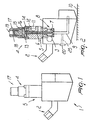
- the reference numeral 1 designates a spreading head particularly for spreading thermoplastic material on intermediate components.
- the head 1 is preferably arranged transversely to the flow of motion of intermediate components on which for example an adhesive is to be applied, and has a first duct 2 for feeding the adhesive at a hole 3 for the transverse distribution of the adhesive at one or more valves 4.
- Each one of the valves 4 comprises a body 5, rigidly coupled to the head 1, which contains a needle 6 arranged axially thereto; the tip 7 of the needle is arranged inside the head 1 at a cup 8, which is connected to a second duct 9 for spreading adhesive at a suitable substrate 10.
- valve 4 there are means suitable to actuate the selective positioning of the needle 6 in an open position, such means being constituted for example by a first air intake 11 obtained laterally from the body 5 and connected to a third duct 12, which is in turn connected to a chamber 13 provided between a rear end 14 of the body 5 directed away from the cup 8 and a disk 15 to which a rear end 16 of the needle 6 is axially coupled, the disk sliding at a cover 17, which is associated with the rear end 14 of the body 5.
- a first air intake 11 obtained laterally from the body 5 and connected to a third duct 12, which is in turn connected to a chamber 13 provided between a rear end 14 of the body 5 directed away from the cup 8 and a disk 15 to which a rear end 16 of the needle 6 is axially coupled, the disk sliding at a cover 17, which is associated with the rear end 14 of the body 5.
- the disk 15, and therefore the needle 6, can move axially with respect to the body 5 and the cover 17 in contrast with at least one elastically deformable element, such as a spring 18.
- the free end of the cover 17 advantageously has a second intake 19, which is preferably suitable to be connected to an air supply, like the first intake 11.
- This solution allows to move the needle 6, for example by pneumatic actuation: it is possible to inject air at the first intake 11, so as to force the uncoupling of the tip 7 of the needle 6 from the cup 8, thus connecting the hole 3 to the second duct 9, so as to allow to spread the adhesive.
- Any injection of air at the second intake 19 instead allows to achieve the movement of the needle 6 until it is arranged in the closed condition, in which its tip 7 closes the end of the second duct 9, so as to prevent the spreading of the adhesive.
- the step for closing the needle 6 can be achieved by setting the spring 18 appropriately.
- a fifth intake 26 which is formed laterally to the body 5 at the chamber 13: at the fifth intake 26 it is possible to arrange an additional pressure sensor or a sensor for detecting the position of the disk 15 connected to the needle 6.
- an appropriate pressure sensor 20 which is suitable to confirm the position of the disk 15 and therefore of the needle 6, for example in the open condition in which the tip 7 of the needle does not close the second duct 9.
- the capacitive sensor 22 can be of the ON/OFF type if one wishes to detect exclusively the correct opening of the needle 6, or of the proportional type if one wishes to check, by means of the same instrument, also the correct closure of the needle 6.
- the spring 18 might be omitted.
- a sensor suitable to check the position assumed by the needle 6 inside the body 5 for example a suitable optical sensor, which can be arranged at a fourth intake 23 formed radially with respect to the body 5 and adapted to connect an outer lateral surface 24 thereof with the seat in which the needle 6 slides.
- the correct closed or open position of the needle 6 can be detected once again.
- an electric position sensor which can also be positioned, for example, at the second intake 19.
- a pressure sensor in the adhesive circuit located downstream of the valve 4 and therefore at the second duct 9; such duct can in fact be connected, by means of a suitable fourth duct 25, to the outside of the head 1; the fourth duct 25 is connected to a suitable pressure sensor 20 for hot-melt, which reports the correct opening of the valve because the pressure of the adhesive circuit downstream of said sensor has been reached.
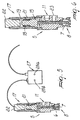
- Figures 5 and 6 illustrate the use of a capacitive sensor 22 in combination with the third intake 21 for the inflow of, for example, air, so as to allow the axial closure movement of the needle 6.
- the cover 17 is elongated in order to allow to accommodate the capacitive sensor 22, which has a suitable axial length.
- the capacitive sensor 22 can be used to check both the closed state and the open state (of the end of the second duct 9) of the needle 6; in the first case, the capacitive sensor 22 can therefore check the closure movement of the needle 6; advantageously, there is a suitable amplifier for the signal that arrives from the capacitor sensor 22 and there is a visual indicator 27, which comprises two LEDs 28a and 28b suitable, for example, to visually indicate the state of the position of the needle 6 and therefore the closure or not of the end of the second duct 9.
Landscapes
- Coating Apparatus (AREA)
- Slide Fasteners, Snap Fasteners, And Hook Fasteners (AREA)
- Materials For Medical Uses (AREA)
- Adhesives Or Adhesive Processes (AREA)
- Polyoxymethylene Polymers And Polymers With Carbon-To-Carbon Bonds (AREA)
- Processing And Handling Of Plastics And Other Materials For Molding In General (AREA)
- Extrusion Moulding Of Plastics Or The Like (AREA)
Applications Claiming Priority (3)
| Application Number | Priority Date | Filing Date | Title |
|---|---|---|---|
| ITTV20010008 | 2001-01-17 | ||
| IT2001TV000008A ITTV20010008A1 (it) | 2001-01-17 | 2001-01-17 | Testata di splmatura particolarmente per materiale termoplastico |
| PCT/EP2002/000170 WO2002057025A2 (en) | 2001-01-17 | 2002-01-10 | Spreading head, particularly for thermoplastic material |
Publications (2)
| Publication Number | Publication Date |
|---|---|
| EP1355743A2 EP1355743A2 (en) | 2003-10-29 |
| EP1355743B1 true EP1355743B1 (en) | 2005-10-26 |
Family
ID=11459969
Family Applications (1)
| Application Number | Title | Priority Date | Filing Date |
|---|---|---|---|
| EP02715408A Expired - Lifetime EP1355743B1 (en) | 2001-01-17 | 2002-01-10 | Spreading head, particularly for thermoplastic material |
Country Status (10)
| Country | Link |
|---|---|
| US (1) | US6983860B2 (enExample) |
| EP (1) | EP1355743B1 (enExample) |
| JP (1) | JP3943025B2 (enExample) |
| CN (1) | CN1225316C (enExample) |
| AT (1) | ATE307680T1 (enExample) |
| AU (1) | AU2002224989A1 (enExample) |
| DE (1) | DE60206877T2 (enExample) |
| ES (1) | ES2251581T3 (enExample) |
| IT (1) | ITTV20010008A1 (enExample) |
| WO (1) | WO2002057025A2 (enExample) |
Families Citing this family (11)
| Publication number | Priority date | Publication date | Assignee | Title |
|---|---|---|---|---|
| DE50210808D1 (de) * | 2002-04-12 | 2007-10-11 | Nordson Corp | Verfahren und Vorrichtung zum Auftragen von Fluiden auf Substraten |
| US20070069041A1 (en) * | 2005-09-27 | 2007-03-29 | Nordson Corporation | Viscous material dispensing systems with parameter monitoring and methods of operating such systems |
| JP5399063B2 (ja) * | 2008-12-26 | 2014-01-29 | 花王株式会社 | 液体塗布装置 |
| JP2010222763A (ja) * | 2009-03-25 | 2010-10-07 | Brother Ind Ltd | 布接着装置、及び圧力制御プログラム |
| DE102009020077A1 (de) | 2009-05-06 | 2010-11-11 | Dürr Systems GmbH | Beschichtungsmittelvorrichtung und Beschichtungsvorrichtung |
| CN104889019A (zh) * | 2014-10-09 | 2015-09-09 | 苏州富强科技有限公司 | 一种自动校针装置 |
| CN206382185U (zh) * | 2017-01-13 | 2017-08-08 | 合肥鑫晟光电科技有限公司 | 一种用于点胶设备的滴胶装置 |
| US12416371B2 (en) * | 2017-11-22 | 2025-09-16 | Illinois Tool Works Inc. | Valve module stroke detection |
| US12110886B2 (en) | 2020-02-28 | 2024-10-08 | Illinois Tool Works Inc. | Piston monitoring assembly |
| CN113798130B (zh) * | 2021-10-13 | 2022-05-17 | 江苏集萃新型药物制剂技术研究所有限公司 | 一种热熔胶制备及涂布一体化设备及方法 |
| TWI807812B (zh) * | 2022-05-06 | 2023-07-01 | 高科晶捷自動化股份有限公司 | 出膠裝置及其出膠方法 |
Family Cites Families (10)
| Publication number | Priority date | Publication date | Assignee | Title |
|---|---|---|---|---|
| US4662540A (en) * | 1984-02-16 | 1987-05-05 | Robotics Incorporated | Apparatus for dispensing medium to high viscosity liquids with liquid flow detector and alarm |
| US4678100A (en) * | 1985-06-17 | 1987-07-07 | Loctite Corporation | Variable flow rate dispensing valve assembly |
| US4922852A (en) * | 1986-10-30 | 1990-05-08 | Nordson Corporation | Apparatus for dispensing fluid materials |
| US4842162A (en) * | 1987-03-27 | 1989-06-27 | Nordson Corporation | Apparatus and method for dispensing fluid materials using position-dependent velocity feedback |
| US4907741A (en) * | 1987-04-09 | 1990-03-13 | Acumeter Laboratories, Inc. | Poppet-valve-controlled fluid nozzle applicator |
| US4987854A (en) * | 1988-12-12 | 1991-01-29 | Nordson Corporation | Apparatus for gas-aided dispensing of liquid materials |
| US5312016A (en) * | 1992-11-04 | 1994-05-17 | Johnstone Pump Company | Mastic applicator system |
| US5782410A (en) * | 1994-10-31 | 1998-07-21 | Weston; Colin K. | Fluid flow control device |
| DE19654514A1 (de) * | 1996-12-27 | 1998-07-02 | Itw Oberflaechentechnik Gmbh | Sprühbeschichtungseinrichtung |
| JPH11197571A (ja) * | 1998-01-12 | 1999-07-27 | Nordson Kk | 吐出ガンの弁機構の開閉速度制御方法及び装置並びに液状体の吐出塗布方法 |
-
2001
- 2001-01-17 IT IT2001TV000008A patent/ITTV20010008A1/it unknown
-
2002
- 2002-01-10 CN CNB02803712XA patent/CN1225316C/zh not_active Expired - Fee Related
- 2002-01-10 ES ES02715408T patent/ES2251581T3/es not_active Expired - Lifetime
- 2002-01-10 DE DE60206877T patent/DE60206877T2/de not_active Expired - Lifetime
- 2002-01-10 EP EP02715408A patent/EP1355743B1/en not_active Expired - Lifetime
- 2002-01-10 US US10/250,747 patent/US6983860B2/en not_active Expired - Lifetime
- 2002-01-10 JP JP2002557527A patent/JP3943025B2/ja not_active Expired - Fee Related
- 2002-01-10 AU AU2002224989A patent/AU2002224989A1/en not_active Abandoned
- 2002-01-10 AT AT02715408T patent/ATE307680T1/de not_active IP Right Cessation
- 2002-01-10 WO PCT/EP2002/000170 patent/WO2002057025A2/en not_active Ceased
Also Published As
| Publication number | Publication date |
|---|---|
| DE60206877D1 (de) | 2005-12-01 |
| AU2002224989A1 (en) | 2002-07-30 |
| CN1486222A (zh) | 2004-03-31 |
| WO2002057025A2 (en) | 2002-07-25 |
| WO2002057025A3 (en) | 2002-10-10 |
| JP3943025B2 (ja) | 2007-07-11 |
| ITTV20010008A0 (it) | 2001-01-17 |
| ES2251581T3 (es) | 2006-05-01 |
| ATE307680T1 (de) | 2005-11-15 |
| ITTV20010008A1 (it) | 2002-07-17 |
| DE60206877T2 (de) | 2006-04-20 |
| US20040065756A1 (en) | 2004-04-08 |
| CN1225316C (zh) | 2005-11-02 |
| EP1355743A2 (en) | 2003-10-29 |
| US6983860B2 (en) | 2006-01-10 |
| JP2004516937A (ja) | 2004-06-10 |
Similar Documents
| Publication | Publication Date | Title |
|---|---|---|
| EP1355743B1 (en) | Spreading head, particularly for thermoplastic material | |
| US4430886A (en) | Method and apparatus for sensing clogged nozzle | |
| EP2623228B1 (en) | Die condition detection | |
| US5542835A (en) | Leak detector for an injection moulding machine | |
| EP3074680B1 (de) | Ventil | |
| CN102821870B (zh) | 用于涂敷可自由流动介质的电涂敷喷头以及涂敷可自由流动介质的涂敷设备 | |
| KR20200037323A (ko) | 개선된 분사 모니터링을 위한 장치 및 방법 | |
| CN104903808A (zh) | 压力调节器 | |
| US9126220B2 (en) | Paint material switching path and colour changer | |
| MXPA03011671A (es) | Electrico sujetador de soldadura resistente. | |
| JP3847436B2 (ja) | ケーブルタイの取り付け工具 | |
| EP0329354A3 (en) | Method and device for measuring the viscosity of a fluid | |
| CN105839381A (zh) | 用于由织物材料制造袋子的方法 | |
| US4391127A (en) | Proximity sensor | |
| JP4043803B2 (ja) | ホットメルト噴射装置 | |
| CA2224370A1 (en) | Method of detecting clogging and granulation method | |
| JP2002103183A (ja) | 回転工具保持確認装置 | |
| US5639487A (en) | Mold core-pin deflection transducer | |
| DE102017003021B3 (de) | Heißleimauftragesystem und - verfahren | |
| CN117920535A (zh) | 一种带异常报警器的涂布点胶外置悬挂随动机构 | |
| US11561090B2 (en) | Contact monitoring on a spindle of a machine tool | |
| KR20190128400A (ko) | 핫 러너 밸브장치 | |
| JPH10118754A (ja) | 成形機の型締め不良検知方法およびその装置 | |
| Chen et al. | On flow pattern around flow front and occurrence of flowless layers in ceramic injection moulding | |
| TR2025010451A1 (tr) | Mfi değeri̇ni̇n ölçülmesi̇ni̇ sağlayan bi̇r si̇stem |
Legal Events
| Date | Code | Title | Description |
|---|---|---|---|
| PUAI | Public reference made under article 153(3) epc to a published international application that has entered the european phase |
Free format text: ORIGINAL CODE: 0009012 |
|
| 17P | Request for examination filed |
Effective date: 20030701 |
|
| AK | Designated contracting states |
Kind code of ref document: A2 Designated state(s): AT BE CH CY DE DK ES FI FR GB GR IE IT LI LU MC NL PT SE TR |
|
| AX | Request for extension of the european patent |
Extension state: AL LT LV MK RO SI |
|
| 17Q | First examination report despatched |
Effective date: 20040603 |
|
| GRAP | Despatch of communication of intention to grant a patent |
Free format text: ORIGINAL CODE: EPIDOSNIGR1 |
|
| RAP1 | Party data changed (applicant data changed or rights of an application transferred) |
Owner name: HIP-MITSU S.R.L. |
|
| GRAS | Grant fee paid |
Free format text: ORIGINAL CODE: EPIDOSNIGR3 |
|
| GRAA | (expected) grant |
Free format text: ORIGINAL CODE: 0009210 |
|
| AK | Designated contracting states |
Kind code of ref document: B1 Designated state(s): AT BE CH CY DE DK ES FI FR GB GR IE IT LI LU MC NL PT SE TR |
|
| AX | Request for extension of the european patent |
Extension state: SI |
|
| PG25 | Lapsed in a contracting state [announced via postgrant information from national office to epo] |
Ref country code: FI Free format text: LAPSE BECAUSE OF FAILURE TO SUBMIT A TRANSLATION OF THE DESCRIPTION OR TO PAY THE FEE WITHIN THE PRESCRIBED TIME-LIMIT Effective date: 20051026 Ref country code: AT Free format text: LAPSE BECAUSE OF FAILURE TO SUBMIT A TRANSLATION OF THE DESCRIPTION OR TO PAY THE FEE WITHIN THE PRESCRIBED TIME-LIMIT Effective date: 20051026 Ref country code: BE Free format text: LAPSE BECAUSE OF FAILURE TO SUBMIT A TRANSLATION OF THE DESCRIPTION OR TO PAY THE FEE WITHIN THE PRESCRIBED TIME-LIMIT Effective date: 20051026 |
|
| REG | Reference to a national code |
Ref country code: GB Ref legal event code: FG4D |
|
| REG | Reference to a national code |
Ref country code: CH Ref legal event code: EP |
|
| REG | Reference to a national code |
Ref country code: IE Ref legal event code: FG4D |
|
| REF | Corresponds to: |
Ref document number: 60206877 Country of ref document: DE Date of ref document: 20051201 Kind code of ref document: P |
|
| REG | Reference to a national code |
Ref country code: CH Ref legal event code: NV Representative=s name: MARK-PAT MODIANO S.A. |
|
| PG25 | Lapsed in a contracting state [announced via postgrant information from national office to epo] |
Ref country code: IE Free format text: LAPSE BECAUSE OF NON-PAYMENT OF DUE FEES Effective date: 20060110 |
|
| PG25 | Lapsed in a contracting state [announced via postgrant information from national office to epo] |
Ref country code: SE Free format text: LAPSE BECAUSE OF FAILURE TO SUBMIT A TRANSLATION OF THE DESCRIPTION OR TO PAY THE FEE WITHIN THE PRESCRIBED TIME-LIMIT Effective date: 20060126 Ref country code: DK Free format text: LAPSE BECAUSE OF FAILURE TO SUBMIT A TRANSLATION OF THE DESCRIPTION OR TO PAY THE FEE WITHIN THE PRESCRIBED TIME-LIMIT Effective date: 20060126 Ref country code: GR Free format text: LAPSE BECAUSE OF FAILURE TO SUBMIT A TRANSLATION OF THE DESCRIPTION OR TO PAY THE FEE WITHIN THE PRESCRIBED TIME-LIMIT Effective date: 20060126 |
|
| PG25 | Lapsed in a contracting state [announced via postgrant information from national office to epo] |
Ref country code: MC Free format text: LAPSE BECAUSE OF NON-PAYMENT OF DUE FEES Effective date: 20060131 Ref country code: LU Free format text: LAPSE BECAUSE OF NON-PAYMENT OF DUE FEES Effective date: 20060131 |
|
| PG25 | Lapsed in a contracting state [announced via postgrant information from national office to epo] |
Ref country code: PT Free format text: LAPSE BECAUSE OF FAILURE TO SUBMIT A TRANSLATION OF THE DESCRIPTION OR TO PAY THE FEE WITHIN THE PRESCRIBED TIME-LIMIT Effective date: 20060327 |
|
| REG | Reference to a national code |
Ref country code: ES Ref legal event code: FG2A Ref document number: 2251581 Country of ref document: ES Kind code of ref document: T3 |
|
| ET | Fr: translation filed | ||
| PLBE | No opposition filed within time limit |
Free format text: ORIGINAL CODE: 0009261 |
|
| STAA | Information on the status of an ep patent application or granted ep patent |
Free format text: STATUS: NO OPPOSITION FILED WITHIN TIME LIMIT |
|
| 26N | No opposition filed |
Effective date: 20060727 |
|
| REG | Reference to a national code |
Ref country code: IE Ref legal event code: MM4A |
|
| PG25 | Lapsed in a contracting state [announced via postgrant information from national office to epo] |
Ref country code: TR Free format text: LAPSE BECAUSE OF FAILURE TO SUBMIT A TRANSLATION OF THE DESCRIPTION OR TO PAY THE FEE WITHIN THE PRESCRIBED TIME-LIMIT Effective date: 20051026 |
|
| PG25 | Lapsed in a contracting state [announced via postgrant information from national office to epo] |
Ref country code: CY Free format text: LAPSE BECAUSE OF FAILURE TO SUBMIT A TRANSLATION OF THE DESCRIPTION OR TO PAY THE FEE WITHIN THE PRESCRIBED TIME-LIMIT Effective date: 20051026 |
|
| REG | Reference to a national code |
Ref country code: DE Ref legal event code: R082 Ref document number: 60206877 Country of ref document: DE Representative=s name: ANDRAE WESTENDORP PATENTANWAELTE PARTNERSCHAFT, DE Ref country code: DE Ref legal event code: R082 Ref document number: 60206877 Country of ref document: DE Representative=s name: FARAGO PATENTANWAELTE, DE Ref country code: DE Ref legal event code: R082 Ref document number: 60206877 Country of ref document: DE Representative=s name: SCHIEBER FARAGO PATENTANWAELTE, DE Ref country code: DE Ref legal event code: R082 Ref document number: 60206877 Country of ref document: DE Representative=s name: FARAGO PATENTANWALTS- UND RECHTSANWALTSGESELLS, DE |
|
| REG | Reference to a national code |
Ref country code: FR Ref legal event code: PLFP Year of fee payment: 15 |
|
| REG | Reference to a national code |
Ref country code: FR Ref legal event code: PLFP Year of fee payment: 16 |
|
| REG | Reference to a national code |
Ref country code: FR Ref legal event code: PLFP Year of fee payment: 17 |
|
| PGFP | Annual fee paid to national office [announced via postgrant information from national office to epo] |
Ref country code: FR Payment date: 20171229 Year of fee payment: 17 |
|
| REG | Reference to a national code |
Ref country code: DE Ref legal event code: R082 Ref document number: 60206877 Country of ref document: DE Representative=s name: FARAGO PATENTANWAELTE, DE Ref country code: DE Ref legal event code: R082 Ref document number: 60206877 Country of ref document: DE Representative=s name: SCHIEBER FARAGO PATENTANWAELTE, DE Ref country code: DE Ref legal event code: R082 Ref document number: 60206877 Country of ref document: DE Representative=s name: FARAGO PATENTANWALTS- UND RECHTSANWALTSGESELLS, DE |
|
| REG | Reference to a national code |
Ref country code: DE Ref legal event code: R082 Ref document number: 60206877 Country of ref document: DE Representative=s name: SCHIEBER FARAGO PATENTANWAELTE, DE Ref country code: DE Ref legal event code: R082 Ref document number: 60206877 Country of ref document: DE Representative=s name: FARAGO PATENTANWALTS- UND RECHTSANWALTSGESELLS, DE Ref country code: DE Ref legal event code: R082 Ref document number: 60206877 Country of ref document: DE Representative=s name: FARAGO PATENTANWAELTE, DE |
|
| PGFP | Annual fee paid to national office [announced via postgrant information from national office to epo] |
Ref country code: NL Payment date: 20180129 Year of fee payment: 17 |
|
| REG | Reference to a national code |
Ref country code: DE Ref legal event code: R082 Ref document number: 60206877 Country of ref document: DE Representative=s name: FARAGO PATENTANWALTS- UND RECHTSANWALTSGESELLS, DE Ref country code: DE Ref legal event code: R082 Ref document number: 60206877 Country of ref document: DE Representative=s name: FARAGO PATENTANWAELTE, DE |
|
| PGFP | Annual fee paid to national office [announced via postgrant information from national office to epo] |
Ref country code: DE Payment date: 20180129 Year of fee payment: 17 Ref country code: CH Payment date: 20180108 Year of fee payment: 17 Ref country code: GB Payment date: 20180126 Year of fee payment: 17 Ref country code: ES Payment date: 20180201 Year of fee payment: 17 |
|
| PGFP | Annual fee paid to national office [announced via postgrant information from national office to epo] |
Ref country code: IT Payment date: 20180123 Year of fee payment: 17 |
|
| REG | Reference to a national code |
Ref country code: DE Ref legal event code: R119 Ref document number: 60206877 Country of ref document: DE |
|
| REG | Reference to a national code |
Ref country code: CH Ref legal event code: PL |
|
| REG | Reference to a national code |
Ref country code: NL Ref legal event code: MM Effective date: 20190201 |
|
| GBPC | Gb: european patent ceased through non-payment of renewal fee |
Effective date: 20190110 |
|
| PG25 | Lapsed in a contracting state [announced via postgrant information from national office to epo] |
Ref country code: DE Free format text: LAPSE BECAUSE OF NON-PAYMENT OF DUE FEES Effective date: 20190801 Ref country code: NL Free format text: LAPSE BECAUSE OF NON-PAYMENT OF DUE FEES Effective date: 20190201 Ref country code: FR Free format text: LAPSE BECAUSE OF NON-PAYMENT OF DUE FEES Effective date: 20190131 |
|
| PG25 | Lapsed in a contracting state [announced via postgrant information from national office to epo] |
Ref country code: CH Free format text: LAPSE BECAUSE OF NON-PAYMENT OF DUE FEES Effective date: 20190131 Ref country code: LI Free format text: LAPSE BECAUSE OF NON-PAYMENT OF DUE FEES Effective date: 20190131 Ref country code: GB Free format text: LAPSE BECAUSE OF NON-PAYMENT OF DUE FEES Effective date: 20190110 |
|
| PG25 | Lapsed in a contracting state [announced via postgrant information from national office to epo] |
Ref country code: IT Free format text: LAPSE BECAUSE OF NON-PAYMENT OF DUE FEES Effective date: 20190110 |
|
| REG | Reference to a national code |
Ref country code: ES Ref legal event code: FD2A Effective date: 20200309 |
|
| PG25 | Lapsed in a contracting state [announced via postgrant information from national office to epo] |
Ref country code: ES Free format text: LAPSE BECAUSE OF NON-PAYMENT OF DUE FEES Effective date: 20190111 |