EP1355689B1 - Caracterisation de systemes de masques respiratoires - Google Patents
Caracterisation de systemes de masques respiratoires Download PDFInfo
- Publication number
- EP1355689B1 EP1355689B1 EP01994561A EP01994561A EP1355689B1 EP 1355689 B1 EP1355689 B1 EP 1355689B1 EP 01994561 A EP01994561 A EP 01994561A EP 01994561 A EP01994561 A EP 01994561A EP 1355689 B1 EP1355689 B1 EP 1355689B1
- Authority
- EP
- European Patent Office
- Prior art keywords
- flow
- pressure
- diffuser
- hose
- air
- Prior art date
- Legal status (The legal status is an assumption and is not a legal conclusion. Google has not performed a legal analysis and makes no representation as to the accuracy of the status listed.)
- Expired - Lifetime
Links
Images


Classifications
-
- A—HUMAN NECESSITIES
- A61—MEDICAL OR VETERINARY SCIENCE; HYGIENE
- A61M—DEVICES FOR INTRODUCING MEDIA INTO, OR ONTO, THE BODY; DEVICES FOR TRANSDUCING BODY MEDIA OR FOR TAKING MEDIA FROM THE BODY; DEVICES FOR PRODUCING OR ENDING SLEEP OR STUPOR
- A61M16/00—Devices for influencing the respiratory system of patients by gas treatment, e.g. mouth-to-mouth respiration; Tracheal tubes
- A61M16/0051—Devices for influencing the respiratory system of patients by gas treatment, e.g. mouth-to-mouth respiration; Tracheal tubes with alarm devices
-
- A—HUMAN NECESSITIES
- A61—MEDICAL OR VETERINARY SCIENCE; HYGIENE
- A61M—DEVICES FOR INTRODUCING MEDIA INTO, OR ONTO, THE BODY; DEVICES FOR TRANSDUCING BODY MEDIA OR FOR TAKING MEDIA FROM THE BODY; DEVICES FOR PRODUCING OR ENDING SLEEP OR STUPOR
- A61M16/00—Devices for influencing the respiratory system of patients by gas treatment, e.g. mouth-to-mouth respiration; Tracheal tubes
- A61M16/0057—Pumps therefor
- A61M16/0066—Blowers or centrifugal pumps
- A61M16/0069—Blowers or centrifugal pumps the speed thereof being controlled by respiratory parameters, e.g. by inhalation
-
- A—HUMAN NECESSITIES
- A61—MEDICAL OR VETERINARY SCIENCE; HYGIENE
- A61M—DEVICES FOR INTRODUCING MEDIA INTO, OR ONTO, THE BODY; DEVICES FOR TRANSDUCING BODY MEDIA OR FOR TAKING MEDIA FROM THE BODY; DEVICES FOR PRODUCING OR ENDING SLEEP OR STUPOR
- A61M16/00—Devices for influencing the respiratory system of patients by gas treatment, e.g. mouth-to-mouth respiration; Tracheal tubes
- A61M16/021—Devices for influencing the respiratory system of patients by gas treatment, e.g. mouth-to-mouth respiration; Tracheal tubes operated by electrical means
- A61M16/022—Control means therefor
- A61M16/024—Control means therefor including calculation means, e.g. using a processor
-
- A—HUMAN NECESSITIES
- A61—MEDICAL OR VETERINARY SCIENCE; HYGIENE
- A61M—DEVICES FOR INTRODUCING MEDIA INTO, OR ONTO, THE BODY; DEVICES FOR TRANSDUCING BODY MEDIA OR FOR TAKING MEDIA FROM THE BODY; DEVICES FOR PRODUCING OR ENDING SLEEP OR STUPOR
- A61M16/00—Devices for influencing the respiratory system of patients by gas treatment, e.g. mouth-to-mouth respiration; Tracheal tubes
- A61M16/08—Bellows; Connecting tubes ; Water traps; Patient circuits
- A61M16/0816—Joints or connectors
- A61M16/0841—Joints or connectors for sampling
- A61M16/0858—Pressure sampling ports
-
- A—HUMAN NECESSITIES
- A61—MEDICAL OR VETERINARY SCIENCE; HYGIENE
- A61M—DEVICES FOR INTRODUCING MEDIA INTO, OR ONTO, THE BODY; DEVICES FOR TRANSDUCING BODY MEDIA OR FOR TAKING MEDIA FROM THE BODY; DEVICES FOR PRODUCING OR ENDING SLEEP OR STUPOR
- A61M16/00—Devices for influencing the respiratory system of patients by gas treatment, e.g. mouth-to-mouth respiration; Tracheal tubes
- A61M16/0057—Pumps therefor
- A61M16/0066—Blowers or centrifugal pumps
-
- A—HUMAN NECESSITIES
- A61—MEDICAL OR VETERINARY SCIENCE; HYGIENE
- A61M—DEVICES FOR INTRODUCING MEDIA INTO, OR ONTO, THE BODY; DEVICES FOR TRANSDUCING BODY MEDIA OR FOR TAKING MEDIA FROM THE BODY; DEVICES FOR PRODUCING OR ENDING SLEEP OR STUPOR
- A61M16/00—Devices for influencing the respiratory system of patients by gas treatment, e.g. mouth-to-mouth respiration; Tracheal tubes
- A61M16/06—Respiratory or anaesthetic masks
-
- A—HUMAN NECESSITIES
- A61—MEDICAL OR VETERINARY SCIENCE; HYGIENE
- A61M—DEVICES FOR INTRODUCING MEDIA INTO, OR ONTO, THE BODY; DEVICES FOR TRANSDUCING BODY MEDIA OR FOR TAKING MEDIA FROM THE BODY; DEVICES FOR PRODUCING OR ENDING SLEEP OR STUPOR
- A61M16/00—Devices for influencing the respiratory system of patients by gas treatment, e.g. mouth-to-mouth respiration; Tracheal tubes
- A61M16/10—Preparation of respiratory gases or vapours
- A61M16/105—Filters
- A61M16/1055—Filters bacterial
-
- A—HUMAN NECESSITIES
- A61—MEDICAL OR VETERINARY SCIENCE; HYGIENE
- A61M—DEVICES FOR INTRODUCING MEDIA INTO, OR ONTO, THE BODY; DEVICES FOR TRANSDUCING BODY MEDIA OR FOR TAKING MEDIA FROM THE BODY; DEVICES FOR PRODUCING OR ENDING SLEEP OR STUPOR
- A61M16/00—Devices for influencing the respiratory system of patients by gas treatment, e.g. mouth-to-mouth respiration; Tracheal tubes
- A61M16/10—Preparation of respiratory gases or vapours
- A61M16/105—Filters
- A61M16/106—Filters in a path
-
- A—HUMAN NECESSITIES
- A61—MEDICAL OR VETERINARY SCIENCE; HYGIENE
- A61M—DEVICES FOR INTRODUCING MEDIA INTO, OR ONTO, THE BODY; DEVICES FOR TRANSDUCING BODY MEDIA OR FOR TAKING MEDIA FROM THE BODY; DEVICES FOR PRODUCING OR ENDING SLEEP OR STUPOR
- A61M16/00—Devices for influencing the respiratory system of patients by gas treatment, e.g. mouth-to-mouth respiration; Tracheal tubes
- A61M16/0003—Accessories therefor, e.g. sensors, vibrators, negative pressure
- A61M2016/0015—Accessories therefor, e.g. sensors, vibrators, negative pressure inhalation detectors
- A61M2016/0018—Accessories therefor, e.g. sensors, vibrators, negative pressure inhalation detectors electrical
- A61M2016/0021—Accessories therefor, e.g. sensors, vibrators, negative pressure inhalation detectors electrical with a proportional output signal, e.g. from a thermistor
-
- A—HUMAN NECESSITIES
- A61—MEDICAL OR VETERINARY SCIENCE; HYGIENE
- A61M—DEVICES FOR INTRODUCING MEDIA INTO, OR ONTO, THE BODY; DEVICES FOR TRANSDUCING BODY MEDIA OR FOR TAKING MEDIA FROM THE BODY; DEVICES FOR PRODUCING OR ENDING SLEEP OR STUPOR
- A61M16/00—Devices for influencing the respiratory system of patients by gas treatment, e.g. mouth-to-mouth respiration; Tracheal tubes
- A61M16/0003—Accessories therefor, e.g. sensors, vibrators, negative pressure
- A61M2016/0027—Accessories therefor, e.g. sensors, vibrators, negative pressure pressure meter
-
- A—HUMAN NECESSITIES
- A61—MEDICAL OR VETERINARY SCIENCE; HYGIENE
- A61M—DEVICES FOR INTRODUCING MEDIA INTO, OR ONTO, THE BODY; DEVICES FOR TRANSDUCING BODY MEDIA OR FOR TAKING MEDIA FROM THE BODY; DEVICES FOR PRODUCING OR ENDING SLEEP OR STUPOR
- A61M16/00—Devices for influencing the respiratory system of patients by gas treatment, e.g. mouth-to-mouth respiration; Tracheal tubes
- A61M16/0003—Accessories therefor, e.g. sensors, vibrators, negative pressure
- A61M2016/003—Accessories therefor, e.g. sensors, vibrators, negative pressure with a flowmeter
- A61M2016/0033—Accessories therefor, e.g. sensors, vibrators, negative pressure with a flowmeter electrical
- A61M2016/0039—Accessories therefor, e.g. sensors, vibrators, negative pressure with a flowmeter electrical in the inspiratory circuit
-
- A—HUMAN NECESSITIES
- A61—MEDICAL OR VETERINARY SCIENCE; HYGIENE
- A61M—DEVICES FOR INTRODUCING MEDIA INTO, OR ONTO, THE BODY; DEVICES FOR TRANSDUCING BODY MEDIA OR FOR TAKING MEDIA FROM THE BODY; DEVICES FOR PRODUCING OR ENDING SLEEP OR STUPOR
- A61M2205/00—General characteristics of the apparatus
- A61M2205/15—Detection of leaks
-
- A—HUMAN NECESSITIES
- A61—MEDICAL OR VETERINARY SCIENCE; HYGIENE
- A61M—DEVICES FOR INTRODUCING MEDIA INTO, OR ONTO, THE BODY; DEVICES FOR TRANSDUCING BODY MEDIA OR FOR TAKING MEDIA FROM THE BODY; DEVICES FOR PRODUCING OR ENDING SLEEP OR STUPOR
- A61M2205/00—General characteristics of the apparatus
- A61M2205/33—Controlling, regulating or measuring
- A61M2205/3331—Pressure; Flow
-
- A—HUMAN NECESSITIES
- A61—MEDICAL OR VETERINARY SCIENCE; HYGIENE
- A61M—DEVICES FOR INTRODUCING MEDIA INTO, OR ONTO, THE BODY; DEVICES FOR TRANSDUCING BODY MEDIA OR FOR TAKING MEDIA FROM THE BODY; DEVICES FOR PRODUCING OR ENDING SLEEP OR STUPOR
- A61M2205/00—General characteristics of the apparatus
- A61M2205/50—General characteristics of the apparatus with microprocessors or computers
- A61M2205/502—User interfaces, e.g. screens or keyboards
- A61M2205/505—Touch-screens; Virtual keyboard or keypads; Virtual buttons; Soft keys; Mouse touches
-
- A—HUMAN NECESSITIES
- A61—MEDICAL OR VETERINARY SCIENCE; HYGIENE
- A61M—DEVICES FOR INTRODUCING MEDIA INTO, OR ONTO, THE BODY; DEVICES FOR TRANSDUCING BODY MEDIA OR FOR TAKING MEDIA FROM THE BODY; DEVICES FOR PRODUCING OR ENDING SLEEP OR STUPOR
- A61M2205/00—General characteristics of the apparatus
- A61M2205/70—General characteristics of the apparatus with testing or calibration facilities
-
- A—HUMAN NECESSITIES
- A61—MEDICAL OR VETERINARY SCIENCE; HYGIENE
- A61M—DEVICES FOR INTRODUCING MEDIA INTO, OR ONTO, THE BODY; DEVICES FOR TRANSDUCING BODY MEDIA OR FOR TAKING MEDIA FROM THE BODY; DEVICES FOR PRODUCING OR ENDING SLEEP OR STUPOR
- A61M2230/00—Measuring parameters of the user
- A61M2230/40—Respiratory characteristics
- A61M2230/46—Resistance or compliance of the lungs
Definitions
- the invention relates to a method of determining air flow characteristics of a mask system connected to CPAP apparatus, and to a CPAP apparatus.
- CPAP Continuous Positive Airway Pressure
- OSA Obstructive Sleep Apnea
- Some devices for treating sleep disordered breathing (SDB) or assisting ventilation provide two pressure levels, one during patient inhalation and a different pressure during patient exhalation.
- the switching between two pressures may be triggered by a timer, a pressure sensor, a flow sensor, a volume sensor or some combination using known techniques.
- OSA is an example of a broader class of disorders generally referred to as sleep disordered breathing (SDB).
- SDB sleep disordered breathing
- a reference to apparatus for the treatment of OSA is intended to include a reference to apparatus for treating SDB.
- Nasal CPAP apparatus for treating SBD form a special subgroup within the broader group of mechanical ventilators. Whilst mechanical ventilators are often closed systems with respect to airflow, the blower, conduit and patient interface system used for the treatment of sleep disordered breathing is typically an open system with respect to airflow.
- the patient interface in a system for treating SOB typically includes a diffuser which produces a deliberate air leak which, amongst other things, reduces rebreathing of exhaled air.
- a diffuser which produces a deliberate air leak which, amongst other things, reduces rebreathing of exhaled air.
- the mask is not correctly positioned on the face, or unsuitable for a particular face, there may be leak around the periphery of the face-contacting portion of the mask.
- the "black box” which incorporates the blower, switches, power supply and control circuitry is sometimes termed a "flow generator".
- a source of high pressure air may be connected to a controllable valve arrangement to provide air at the required pressure and flow rates. All of these systems may be described as controllable sources of breathable gas.
- WO 00/27457 describes a mask system connected to CPAP apparatus comprising a flow generator, the mask system including an air delivery hose and a patient interface including a diffuser, the flow generator including a controllable air blower.
- the apparatus has various transducers, such as sensors, to measure flow rate or pressure of the air flow at chosen locations in order to detect faults.
- each mask system has different characteristics, such as different pressure drop along the conduit and diffuser flow. Furthermore, the characteristics of different samples of a given mask system can vary due to variation during manufacturing. In order that a given flow generator is able to work with a range of mask systems, each mask system must be characterized by the manufacturer for use with the flow generator and the characteristics may be stored in the flow generator, for example, or in some other recordable medium device. In the event that new mask systems are developed, the flow generator may need to be returned to the manufacturer to be tested with the new mask system.
- the present invention seeks to provide a method which enables the characteristics of a wide range of patient interfaces and conduits to be determined such that there is no need for a flow generator to be returned to the manufacturer.
- a method of determining air flow characteristics of a mask system connected to CPAP apparatus comprising a flow generator, the mask system including an air delivery hose and a patient interface including a diffuser, the flow generator including a controllable air blower, and a flow sensor and a pressure sensor being provided, the method being charaterised in comprising:
- a method of an embodiment of the invention may further comprise processing the air flow characteristics of the air delivery hose and the air flow characteristics of the diffuser.
- the determining of the air flow characteristics of the air delivery hose is calculated as a function of a quadratic expression with two hose constants.
- the determining of the air flow characteristics of the mask system is calculated as a function of a quadratic expression with two diffuser constants (DiffA, Diff B).
- the patient interface is blocked by a flow blocking member having a shape representative of a human nose or a human face.
- the present invention also extends to a CPAP apparatus as defined in the apended claim 11.
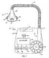
- Figs. 1 - 3 show an embodiment of a CPAP apparatus of the invention.
- the CPAP apparatus generally indicated at 10, comprises a controllable air blower or flow generator 12 which is in communication with a respiratory mask system, generally indicated at 14.
- the respiratory mask system 14 includes an air delivery hose 16 that connects the respiratory mask system 14 to the flow generator 12 to supply breathable gas through the respiratory mask system 14 to the patient.
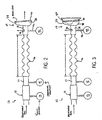
- the flow generator 12 is configured to deliver a supply of breathable gas to the patient at a specific flow rate and pressure. As shown in Figures 2 and 3 , the flow generator 12 includes a flow sensor 13 and a pressure sensor 15, to measure flow rate and pressure respectively, at an output 17 of the flow generator 12. The output 17 is connected to the air delivery hose 16.
- the flow generator 12 is configured to supply a controllable source of breathable gas, such as oxygen, to the mask system 14 through the air delivery hose 16 during a test period, which will be described in greater detail below.
- a controllable source of breathable gas such as oxygen
- a plurality of flow measurements, for example, flow rate and pressure, of the controllable source of breathable gas are made during the test period at the output 17 of the flow generator 12.
- the flow generator 12 is capable of delivering the source of breathable gas at a flow up to about 100 Umin, for example, at low pressures, ranging from about 0.25 to about 2 cm H 2 O, smoothly and accurately.
- the flow generator 12 can be provided within the housing 18, which can be made from a sufficiently resilient material, such as plastic or metal. Alternatively, the flow generator 12 can be provided remote from the housing 18.
- the housing 18 includes an opening or slot 19 formed in its exterior which may be used as a handle to transport the CPAP apparatus 10.
- the resilient structure of the housing 18 substantially helps support and protect a processor 20, an impeller 22, a motor 24, a servo-control circuit 26, a display 28, a user interface 30 and a controller 32.
- the controller 32 is configured to control the operation of one or more of the processor 20, the impeller 22, the motor 24, the servo-control circuit 26, the display 28, and the user interface 30, as is generally known.
- the user interface 30 and the display 28 are provided in the housing 18 of the CPAP apparatus 10 and are configured to control and manipulate various functions that may be available to the particular CPAP apparatus 10.
- the user interface 30 may be in the form of a barcode, a keyboard, a mouse, a touch screen, a remote terminal or a voice activation system, for example, to accept input from a user, such as a patient or doctor, for example.
- the display 28 may be a touch screen display or an LCD display and may be configured to display various parameters, such as, for example, air flow characteristics of the air delivery hose 16 or mask system 14, the flow rate measured by the flow sensor 13 and the pressure measured by the pressure sensor 15.
- the display 28 can be configured to display delivered flow (by the flow generator 12) with a prompt so that a user or patient can minimize delivered flow before making air flow characteristic measurements.
- the motor 24 is coupled to the impeller 22 to drive the impeller 22.
- the impeller 22 When driven, the impeller 22 generates a source of breathable gas, which can be supplied through the air delivery hose 16 to the mask system 14.
- the processor 20 is configured and arranged to determine a plurality of air flow characteristics of the respiratory mask system 14 using a plurality of flow measurements made during the test period. These air flow characteristics could be displayed on the display 28, for example.
- the processor 20 may be capable of performing various calculations to a specific accuracy, for example, 32 bit floating point.
- the processor 20 may be configured and arranged to perform calculations at any other accuracy as well, which could depend on the desired calculation and application, for example.
- the servo-control circuit 26 cooperates with the processor 20 and the flow generator 12 to allow for the maintenance of a pressure in the mask system 14, for example, within strictly defined error limits.
- Table 1 models a preferred minimum accuracy and a preferred optimal accuracy for various system parameters, such as delivered flow accuracy, stability and linearity and delivered pressure accuracy and stability.
- Table 1 Parameter Minimum Accuracy Optimal Accuracy Delivered flow accuracy +/- 3L/min (same as mask leak requirement) +/-1.5 L/min (1 ⁇ 2 mask leak requirement) Delivered flow stability Same as mask leak requirement over any period of use 1 ⁇ 2 mask leak requirement over any period of use Delivered flow linearity ⁇ 5% deviation from straight line ( Fig. 5 ) ⁇ 2% deviation from straight line ( Fig.
- the air delivery hose 16 may be any conventional hose. However, in some applications, such as in some hospital and clinical situations with acute or sick patients, different requirements may be needed for the hose system 16. In particular it is likely that an antibacterial filter with ongoing maintenance would be beneficial in those situations.
- an abbreviated calibration of the hose may be done automatically or manually every time the mask is disconnected from the patient.
- This system could also track use of antibacterial filters and warn when they are getting clogged and need to be changed.
- the mask system 14 is connected to an air supply source provided by the flow generator 12 by the air delivery hose 16.
- the mask system 14 may be integrally attached to the air delivery hose 16 or may be connected thereto with fasteners, such as clamps, for replacement or interchangeability of the mask system 14.
- the air supply source may deliver unregulated air to the mask system 14, because the pressure sensor 15 associated with the flow generator 12 may be configured to determine the required pressure of the air needed by the patient by the relative strength of the patient's breaths.
- the mask system 14 includes a patient interface or mask 34 and an elongated projecting portion 35, which may be connected to the air delivery hose 16.
- a diffuser 36 in the form of an orifice, is formed in the elongated projecting portion 35 and diffuses air exhaled by the patient.
- Other masks may be used with apparatus according to an embodiment of the invention.
- apparatus in accordance with the invention may be used to determine the flow characteristics of a mask system such as the MIRAGETM mask, the ULTRA MIRAGETM mask, the BUBBLETM mask or the MODULARTM mask, all of which are manufactured by ResMed Limited, Australia.
- the patient interface 34 may be any one of a number of different patient interfaces, such as a nasal mask, a nose and mouth mask, a full-face mask, nasal prongs (or cannulae) and nasal pillows.
- the patient interface 34 includes some form of mask retaining feature, such as headgear, to position the mask system 14 on the patient's face and to counterbalance the force which results from the application of pressurized air which seeks to push the mask 34 or mask system 14 off the patient's face.
- the diffuser 36 can be passive or semi-active, e.g., the diffuser 36 could be an opening, a plurality of openings, or an opening or openings that are partially covered, grated etc., that allow air to pass through..
- the mask 34 is shown as a nasal mask and has a generally triangularly-shaped chamber 38 constructed from a relatively rigid material, such as polycarbonate, with an open side which, when in use, is positioned against the patient's face.
- a relatively rigid material such as polycarbonate
- the edge of the open side i.e., a face-contacting portion 40, helps form a seal on the patient's face.
- the face-contacting portion 40 is typically soft to assist with patient comfort and may be made from foam, rubber or polystyrene, for example.
- mask 34 includes a number of headgear-receiving portions 42 extending from opposite sides thereof to receive straps or other portions of the headgear, for example. Patient comfort is important and should be considered when selecting the type of mask 34 since the patient may be sleeping or resting while wearing the mask 34.
- the pressure in the patient interface can be estimated once the conduit characteristics have been determined.
- a pressure transducer in the patient interface or to be connected to the patient interface via a sense tube.
- such an embodiment of the invention can be used in conjunction with a wide variety of commercially available masks which do not include pressure transducers in the mask, or pressure sense tubes in the mask.
- a pressure sensor 44 for example, a pressure transducer
- a sensing tube can be connected between an appropriate port on the patient interface 34 and a pressure sensor (not shown) located remotely from the patient interface 34, such as in the air blower housing 18.
- the CPAP apparatus can include an under or over pressure alarm coupled to a pressure tube extending from the mask 34 for accurate measurements of mask pressure.
- This configuration may generally be best suited to provide variable pressure regimes.
- the under or over pressure alarm can measure pressure at the flow generator 12 to allow the maintenance of a continuous accurate model of the hose pressure drop and so allows the alarm system to measure pressure at the flow generator 12.
- the CPAP apparatus 10 may include a slot, for example, that is configured to allow a removable storage medium to be inserted into the slot for storing collected data or characteristics for common masks and hose systems.
- the slot could be conveniently located anywhere on the CPAP apparatus, but should be located so minimal effort is required to insert and remove the storage medium from the CPAP apparatus 10.
- the removable storage medium could be a magnetic or flash type of storage, which is commonly compatible with personal computers, handheld devices, cameras, and printers and is capable of storing hundreds of megabytes of data at a minimum.
- the removable storage medium could contain information about the mask system 14 or may include other parameters provided by a physician, for example.
- the removable storage medium would have read from and write to capabilities and information that was imparted to the removable storage medium by the patient or the physician could be utilized by the CPAP apparatus 10 to control certain parameters.
- different masks have different flow characteristics, it would be beneficial to impart information about the mask onto the removable storage medium so the CPAP apparatus could vary the provided air pressures or flow rates accordingly.
- it would be inexpensive for the patient to change masks because the mask information and characteristics could easily be changed to accommodate different masks, for example. Data for each particular mask can be provided by the mask manufacturer and when the patient purchases the mask, he or she could simply insert the card into the CPAP apparatus 10 and the apparatus could reconfigure itself accordingly.
- the flow generator 12 may be preset to operate within a given speed range giving coarse control of the pressure which is delivered to the patient through the air delivery hose 16.
- the actual pressure at the patient interface will vary throughout the respiratory cycle. For instance, as the patient or other user inhales, the pressure measured at the patient interface increases while during exhalation the measured pressure decreases.
- the average air flow to the patient is assumed to be zero, as the air supplied to the patient is effectively balanced by air exhaled by the patient.
- the pressure delivered to the entrance of the patient's airways can be estimated by measuring the pressure at the output 17 of the flow generator 12 and applying a correction factor in accordance with the known characteristics of the relevant conduit and patient interface, as will be described in greater detail below.
- A is attributed to friction losses, which are proportional to flow
- B is based on the Bernoulli equation where pressure drop is proportional to flow squared (Flow 2 ).
- a flow blocking member 50 ( Fig. 3 ) can be provided to block portions of the patient interface 34 and the projecting portion 35 so that flow through the mask system 14 is blocked.
- a shape of the flow blocking member 50 is complementary to a shape of the patient interface 34.
- the shape of the flow blocking member 50 may be representative of a human nose, a human face or a partial human face.
- the flow blocking member 50 may be shaped such that it can serve to block flow in a number of masks having different configurations.
- the flow blocking member 50 may be affixed to the flow generator 12 so that it does not become lost and remains easily accessible to the patient, or the flow blocking member 50 can be free from attachment to the flow generator 12.
- Fig. 4 is a flow chart illustrating a method of an embodiment of the invention for determining air flow characteristics of a mask system.
- the method commences at 400.
- the pressure sensor 15 associated with the flow generator 12 is zeroed
- the flow sensor 13 associated with the flow generator 12 is zeroed.
- the delivered flow, as measured by the flow sensor 13, and the delivered pressure, as measured by the pressure sensor 15, should be kept as constant as possible.
- Hose A / x ⁇ X 2 - X ⁇ x 2 yX 2 - xY 2
- Hose B / x ⁇ X 2 - x 2 ⁇ X xY - yX .
- the pressure drops in the air delivery hose 16 at the first and second flow rates are represented as y and Y, respectively.
- Leaks in the diffuser 36 at a lower flow rate and at a higher flow rate are represented as x and X, respectively.
- the first and second flow rates (or pressures) provide substantially better resolution with one at a high value and the other at half of the high value. This relationship is shown in Fig. 5 , wherein test 1 is a flow rate having half the value of test 2, which is a flow rate having a high value.
- a maximum linear deviation from the straight line 100 (about 5%) is shown corresponding to flow rate represented by test 1, which is the value equal to half of the high value.
- the mask calibration procedure produces the following measurements, as shown in Table 2, which are analyzed to produce the A and B coefficients for the mask system model described above: Table 2 Name Parameter Example value HoseTF1 Lower test flow for hose 40 L/min HoseTP1 Pressure drop down hose at lower test flow 0.1 to 0.4 cmH 2 O HoseTF2 Upper test flow for hose 80 to 100 L/min HoseTP2 Pressure drop down hose at upper test flow 1 to 4 cmH 2 O DiffTP1 Lower diffuser test pressure 6 cmH 2 O DiffTF1 Flow at lower diffuser test pressure 10 to 20 L/min DiffTP2 Upper diffuser test pressure 12 cmH 2 O DiffTF2 Flow at upper diffuser test pressure 15 to 40 L/min
- the mask pressure can be estimated from known hose characteristics without requiring a pressure transducer in the mask, or directly connected to the mask.
- the apparatus 10 prompts a user for a determination on whether the mask 34 or mask 14 is blocked or not. If the respiratory mask 34 is open, as denoted by 412, the apparatus 10 continues to prompt the user until the user blocks the mask 34, for example, with the flow blocking member 50. If the mask 34 is blocked, as denoted by 414, a first test pressure is applied to the diffuser 36. The mask 34 can be blocked for example, by positioning the flow blocking member 50 adjacent a patient interface of the mask 34, for example.
- the first test pressure or delivered air flow
- the CPAP apparatus prompts a user to determine whether the mask system 14 is leaking. If so, at 420, control proceeds back to 410. If not, control proceeds to 424, at which the flow of the diffuser 36 at a first test pressure is measured and after which, at 426, the CPAP apparatus prompts (actually reminds) the patient or user to keep the mask blocked with the flow blocking member 50.
- the CPAP apparatus prompts (actually reminds) the patient or user to keep the mask 34 blocked with the flow blocking member 50.
- the user is prompted to shut off the CPAP apparatus at 432.
- processing begins.
- the quadratic expression having constants Diff A and Diff B can be used to determine or calculate air flow characteristics of the mask 34.
- the background level of the flow generator 12 can be measured to characterize background noise during testing of the diffuser.
- the background level can be subtracted from a raw snore signal to derive a true snore level on the CPAP apparatus 10 and other flow generators that measure snore. This procedure could be used to calibrate the snore scale factor in the case where the flow blocking member 50 includes some type of snore source to perform in this manner.
- test pressure or flow is held substantially constant for about 10 to about 20 seconds with mean flows and pressures being recorded during this time period.
- the mask system 14 is pressurized at the highest test pressure to expose any leaks. This can be checked by observing the displayed flow on the display, for example, and adjusting the flow blocking member 50 so that the displayed flow remains substantially constant and at a minimum.
- HoseDrop HoseA*F + HoseB*F 2 .
- Hose test flow 1 40 Umin Test pressure for this 0.75 cmH 2 O Hose test flow 2 80 Umin Test pressure for this 2 cmH 2 O Diffuser test pressure 1 5.9125 cmH 2 O Diffuser flow at this pressure 20 Umin Diffuser test pressure 2 21.0125 cmH 2 O Diffuser flow at this pressure 50 L/min Derived results: Hose A Hose B DiffA DiffB 0.0125 1.5625*10 -4 0.2 4*10 -3
- An apparatus may be provided to undertake the method, the apparatus being provided with a blower or flow generator, the blower including a pressure and flow sensor, and the apparatus including a display for promoting a user and a mask blocking tool.
- the apparatus is programmed to perform the series of steps shown in Table 4. Table 4 shows what the flow generator does during each step, what the user is prompted to do and how the user should respond to the prompt.
- the system is zeroed. Steps 2 and 3 constitute the part of the sequence where the hose characteristics are measured.
- steps 4 and 5 the user is prompted to block the mask and the blocking is subsequently verified.
- steps 6 and 7 the diffuser characteristics are measured whilst the mask is blocked.
- step 8 the data collected during the previous steps is processed to determine the conduit characteristics and the diffuser characteristics. Also, in step 9, the data and results are checked for consistency.
- Table 4 Step Flow Generator does Prompt User response 1 Zero of pressure and flow sensors Ensure that mask is connected to flow generator and not patient Set up mask system as required Press key when ready 2 Measure hose pressure drop at test flow 1 ( ⁇ 40 L/min) Measuring hose characteristics Wait 3 Measure hose pressure drop at test flow 2 ( ⁇ 80 L/min) Measuring hose characteristics Wait 4 Ask operator to block mask Block mask with the mask blocking tool Press key when done 5 Test for properly blocked mask: Apply diffuser test pressure 2 ( ⁇ 12 cmH2O) and display delivered flow Check that the mask is not leaking and that display flow is minimum Press key when done 6 Measure diffuser at test pressure 2 ( ⁇ 12 cmH2O) Testing diffuser, Hold mask blocked Wait 7 Measure diffuser at test pressure 1 ( ⁇ 6 cmH2O) Testing diffuser, Hold mask blocked Wait 8 Turn off flow generator Finished, remove mask from blocking tool Remove tool and
- test pressure or flow should be held steady for 10 to 20 seconds with mean flows and pressures recorded during this time.
- the measured pressures during steps 2 and 3 can be very low (0.2 to 2 cmH2O). This may entail accurate and steady control of the fan at unusually low (for CPAP) pressures. The ideal mode of control is constant flow delivery.
- step 5 a good leak proof seal is provided using the blocking tool. During this step, the mask is pressurised at the highest test pressure to expose any leaks. This can be checked by observing the displayed flow and adjusting the blocking tool so this is steady and minimum. 4. There are a number of consistency checks that can be done in step 8 to check the characterisation. Some of these are:
- Methods of embodiments of the invention may use predetermined characteristics of the air delivery hose in order to determine the air flow characteristics of the diffuser.
- a characterisation procedure may only require the second step, the first step already having been done at an earlier stage.
- a technician or physician were to carry out one complete characterisation, that is both conduit and mask diffuser, and then at a later stage only change the mask and diffuser, it would not be necessary to recharacterise the conduit.
- the apparatus were to be used with a conduit whose character was already known and stored in the apparatus (for example, having been determined in a factory test), only the second step of the procedure would be necessary.
Landscapes
- Health & Medical Sciences (AREA)
- Emergency Medicine (AREA)
- Pulmonology (AREA)
- Engineering & Computer Science (AREA)
- Anesthesiology (AREA)
- Biomedical Technology (AREA)
- Heart & Thoracic Surgery (AREA)
- Hematology (AREA)
- Life Sciences & Earth Sciences (AREA)
- Animal Behavior & Ethology (AREA)
- General Health & Medical Sciences (AREA)
- Public Health (AREA)
- Veterinary Medicine (AREA)
- Measurement Of The Respiration, Hearing Ability, Form, And Blood Characteristics Of Living Organisms (AREA)
- Respiratory Apparatuses And Protective Means (AREA)
- Measuring Fluid Pressure (AREA)
- Separation Using Semi-Permeable Membranes (AREA)
Claims (11)
- Procédé de détermination de caractéristiques de flux d'air d'un système de masque (14) connecté à un appareil de ventilation spontanée avec pression expiratoire positive, comprenant un générateur de flux (12), le système de masque (14) comprenant un tuyau de distribution d'air (16) et une interface patient (34) comprenant un diffuseur (36), le générateur de flux (12) comprenant un souffleur d'air contrôlable (12), un capteur de flux (13) et un capteur de pression (15), le procédé étant caractérisé en ce qu'il comprend les étapes consistant à :déterminer les caractéristiques de flux d'air du conduit de distribution d'air (16) en utilisant des mesures de flux réalisées pendant une première période de test quand le flux à travers l'interface de patient (34) est ouvert ;mesurer la pression dans l'interface de patient (34) pendant une deuxième période de test, quand le flux à travers l'interface patient est bloqué ; etdéterminer les caractéristiques de flux d'air du diffuseur (36) en utilisant les caractéristiques de flux d'air du conduit de distribution d'air (16) déterminées pendant la première période de test et les mesures de pression réalisées pendant la deuxième période de test.
- Procédé selon la revendication 1, comprenant en outre le traitement des caractéristiques de flux d'air du conduit de distribution d'air (16) et des caractéristiques de flux d'air du diffuseur (36).
- Procédé selon la revendication 1 ou la revendication 2, dans lequel la détermination des caractéristiques de flux d'air du conduit de distribution d'air (16) est calculée en fonction d'une expression quadratique avec deux constantes de conduit.
- Procédé selon la revendication 3, dans lequel les deux constantes de conduit comprennent :
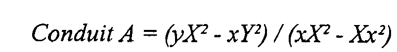

dans lesquelles x est un flux d'air inférieur pour le conduit de distribution d'air, X est un flux d'air supérieur pour le conduit de distribution d'air, y est une chute de pression dans le conduit de distribution d'air au flux d'air inférieur et Y est une chute de pression dans le conduit de distribution d'air au flux d'air supérieur. - Procédé selon la revendication 4, dans lequel les deux constantes de conduit (Conduit A, Conduit B) sont utilisées pour calculer une véritable pression de test inférieure (TrueDiffTP1) et une véritable pression de test supérieure (TrueDiffTP2) pour le diffuseur (36),
dans lequel la véritable pression de test inférieure est définie comme TrueDiffTP1 = DiffTP1 - ConduitA*x - ConduitB*ConduitA(x)2, où DiffTP1 est le flux de diffuseur à une pression inférieure pour le diffuseur, et
dans lequel la véritable pression de test supérieure est définie comme TrueDiffTP2 = DiffTP2 - ConduitA*X - ConduitB*ConduitA(X)2, où DiffTP2 est le flux de diffuseur à une pression supérieure pour le diffuseur. - Procédé selon l'une quelconque des revendications précédentes, dans lequel la détermination des caractéristiques de flux d'air du système de masque est calculée en fonction d'une expression quadratique avec deux constantes de diffuseur (Diff A, Diff B).
- Procédé selon la revendication 6, dans lequel les deux constantes de diffuseur comprennent :


où v est une pression inférieure pour le diffuseur, V est une pression supérieure pour le diffuseur, z est une véritable pression inférieure pour le diffuseur et Z est une véritable pression supérieure pour le diffuseur. - Procédé selon l'une quelconque des revendications précédentes, comprenant en outre le blocage de l'interface du patient (34) avec un élément de blocage de flux (50) ayant une forme qui est complémentaire de la forme de l'interface du patient.
- Procédé selon la revendication 8, dans lequel la forme de l'élément de blocage de flux (50) est représentative d'au moins un élément parmi le nez humain et le visage humain.
- Procédé selon la revendication 8 ou la revendication 9, comprenant en outre la fixation de l'élément de blocage de flux (50) à l'interface du patient (34).
- Appareil de ventilation spontanée avec pression expiratoire positive, utile dans le traitement d'un patient, l'appareil de ventilation spontanée avec pression expiratoire positive, comprenant :un logement (18) ;un système de masque respiratoire (14) en communication avec le logement, le système de masque respiratoire (14) comprenant un conduit de distribution d'air (16) et une interface de patient (34) comprenant un orifice de diffuseur (36) ;un générateur de flux (12) configuré pour fournir une alimentation en gaz respirable à un patient et étant associé au logement (18), le générateur de flux pouvant être contrôlé pour fournir une source contrôlable de gaz respirable à l'interface du patient (34) à travers le conduit de distribution d'air (16) ;le générateur de flux (12) comprenant en outre un capteur de flux (13), un capteur de pression (15) et un processeur (20) ;caractérisé en ce que
le capteur de flux (13) est configuré pour réaliser des mesures de flux pendant une première partie d'une période de test quand le flux à travers l'interface du patient est ouvert, afin de déterminer des caractéristiques de flux d'air du conduit de distribution d' air ;
le capteur de pression (15) est configuré pour mesurer la pression dans l'interface du patient (34), pendant une deuxième partie de la période de test quand le flux à travers l'interface du patient est bloqué ; et
le processeur (20) est configuré pour déterminer des caractéristiques de flux d'air de l'orifice diffuseur (36), utilisant les caractéristiques de flux d'air du conduit de distribution d'air (16) déterminées pendant la première partie de la période de test et les mesures de pression faites par le capteur de pression (15) pendant la deuxième partie de la période de test.
Applications Claiming Priority (3)
| Application Number | Priority Date | Filing Date | Title |
|---|---|---|---|
| US25860600P | 2000-12-29 | 2000-12-29 | |
| US258606P | 2000-12-29 | ||
| PCT/AU2001/001673 WO2002053217A1 (fr) | 2000-12-29 | 2001-12-24 | Caracterisation de systemes de masques respiratoires |
Publications (3)
| Publication Number | Publication Date |
|---|---|
| EP1355689A1 EP1355689A1 (fr) | 2003-10-29 |
| EP1355689A4 EP1355689A4 (fr) | 2007-08-08 |
| EP1355689B1 true EP1355689B1 (fr) | 2010-05-26 |
Family
ID=22981319
Family Applications (1)
| Application Number | Title | Priority Date | Filing Date |
|---|---|---|---|
| EP01994561A Expired - Lifetime EP1355689B1 (fr) | 2000-12-29 | 2001-12-24 | Caracterisation de systemes de masques respiratoires |
Country Status (6)
| Country | Link |
|---|---|
| US (5) | US7987847B2 (fr) |
| EP (1) | EP1355689B1 (fr) |
| JP (3) | JP4336496B2 (fr) |
| AT (1) | ATE468874T1 (fr) |
| DE (2) | DE60142256D1 (fr) |
| WO (1) | WO2002053217A1 (fr) |
Families Citing this family (136)
| Publication number | Priority date | Publication date | Assignee | Title |
|---|---|---|---|---|
| AUPO163896A0 (en) | 1996-08-14 | 1996-09-05 | Resmed Limited | Determination of respiratory airflow |
| USRE38533E1 (en) * | 1998-09-11 | 2004-06-15 | Life Corporation | Portable emergency oxygen and automatic external defibrillator (AED) therapy system |
| EP1210139B1 (fr) | 1999-08-05 | 2006-10-11 | MAP Medizin-Technologie GmbH | Dispositif d'alimentation en gaz respiratoire et dispositif d'humidification |
| US7391929B2 (en) | 2000-02-11 | 2008-06-24 | Sony Corporation | Masking tool |
| ATE468874T1 (de) | 2000-12-29 | 2010-06-15 | Resmed Ltd | Charakterisierung von maskensystemen |
| AU2003214570A1 (en) | 2002-03-08 | 2003-09-22 | Kaerys S.A. | A breathing apparatus with computation of the airflow provided to the patient using only pressure sensors |
| US7448383B2 (en) | 2002-03-08 | 2008-11-11 | Kaerys, S.A. | Air assistance apparatus providing fast rise and fall of pressure within one patient's breath |
| US7438073B2 (en) | 2002-03-08 | 2008-10-21 | Kaerys S.A. | Air assistance apparatus for computing the airflow provided by only means of pressure sensors |
| US8381729B2 (en) | 2003-06-18 | 2013-02-26 | Breathe Technologies, Inc. | Methods and devices for minimally invasive respiratory support |
| US7588033B2 (en) | 2003-06-18 | 2009-09-15 | Breathe Technologies, Inc. | Methods, systems and devices for improving ventilation in a lung area |
| NZ728764A (en) | 2003-06-20 | 2018-09-28 | ResMed Pty Ltd | Breathable gas apparatus with humidifier |
| AU2003903139A0 (en) | 2003-06-20 | 2003-07-03 | Resmed Limited | Breathable gas apparatus with humidifier |
| US8156937B2 (en) * | 2003-08-04 | 2012-04-17 | Carefusion 203, Inc. | Portable ventilator system |
| US7527053B2 (en) * | 2003-08-04 | 2009-05-05 | Cardinal Health 203, Inc. | Method and apparatus for attenuating compressor noise |
| US7607437B2 (en) * | 2003-08-04 | 2009-10-27 | Cardinal Health 203, Inc. | Compressor control system and method for a portable ventilator |
| US8118024B2 (en) | 2003-08-04 | 2012-02-21 | Carefusion 203, Inc. | Mechanical ventilation system utilizing bias valve |
| BRPI0413275A (pt) * | 2003-08-04 | 2006-10-10 | Pulmonetic Systems Inc | ventilador portátil, e, sistema de ventilador portátil |
| CN1905917B (zh) | 2003-08-18 | 2011-08-03 | 门罗生命公司 | 通过鼻界面进行无创通气的方法和装置 |
| CA2541945A1 (fr) * | 2003-09-03 | 2005-03-17 | Comair Rotron, Inc. | Appareil et procede de maintien d'une condition de fonctionnement d'une soufflante |
| US8037896B2 (en) | 2004-03-09 | 2011-10-18 | Mks Instruments, Inc. | Pressure regulation in remote zones |
| US6986359B2 (en) * | 2004-03-09 | 2006-01-17 | Mks Instruments, Inc. | System and method for controlling pressure in remote zones |
| US9144654B2 (en) * | 2004-04-15 | 2015-09-29 | Resmed Limited | Snoring treatment apparatus and methods of managing snorers |
| US7055366B2 (en) * | 2004-05-21 | 2006-06-06 | Upchurch Scientific, Inc. | Flow sensor calibration methods and apparatus |
| CA3093934A1 (en) | 2004-08-20 | 2006-02-23 | Fisher & Paykel Healthcare Limited | Apparatus for measuring properties of gases supplied to a patient |
| JP2008531136A (ja) * | 2005-03-01 | 2008-08-14 | レスメド リミテッド | 呼吸に適したガスを患者に送達する装置用の認識システム |
| US7984002B2 (en) * | 2005-04-29 | 2011-07-19 | Charles River Analytics, Inc. | Automatic source code generation for computing probabilities of variables in belief networks |
| EP1893265B1 (fr) | 2005-06-14 | 2013-12-04 | ResMed Limited | Appareil permettant a un patient de mieux se conformer a un traitement cpap |
| US8316848B2 (en) | 2005-08-15 | 2012-11-27 | Resmed Limited | CPAP systems |
| JP2009508645A (ja) | 2005-09-20 | 2009-03-05 | ルッツ フレイテッグ, | 患者の呼吸を補助するためのシステム、方法、および装置 |
| NZ700746A (en) | 2005-10-14 | 2015-09-25 | Resmed Ltd | Flow generator message system |
| EP1800705B1 (fr) * | 2005-12-21 | 2018-01-24 | ResMed Limited | Système et procédé d'identification pour des composants de masques et inhalateurs |
| US7747319B2 (en) * | 2006-03-17 | 2010-06-29 | Zoll Medical Corporation | Automated resuscitation device with ventilation sensing and prompting |
| EP2023987B1 (fr) | 2006-05-18 | 2016-11-09 | Breathe Technologies, Inc. | Espaceur de trachéostome |
| US20100113957A1 (en) * | 2006-09-11 | 2010-05-06 | Anthony Williams | System, method and apparatus for monitoring a medical condition |
| US8851073B2 (en) * | 2006-09-29 | 2014-10-07 | Covidien Lp | Patient interface having an integrated system for communicating data to a ventilator |
| WO2008144589A1 (fr) | 2007-05-18 | 2008-11-27 | Breathe Technologies, Inc. | Procédés et dispositifs pour détecter la respiration et fournir une thérapie de ventilation |
| US8365726B2 (en) | 2007-06-07 | 2013-02-05 | Resmed Limited | Tub for humidifier |
| FR2917979B1 (fr) * | 2007-06-28 | 2010-03-19 | Bear Medical | Procede et appareil d'aide a l'expectoration |
| US20090020122A1 (en) * | 2007-07-16 | 2009-01-22 | Helmut Hoffrichter | Respiratory device for treating obstructive sleep apnea and method for controlling said device |
| AU2008203812B2 (en) * | 2007-08-17 | 2014-10-02 | ResMed Pty Ltd | Methods and Apparatus for Pressure Therapy in the Treatment of Sleep Disordered Breathing |
| CN107041987B (zh) * | 2007-08-22 | 2021-08-10 | 纽约州立大学研究基金会 | 呼吸气体供应和共享系统及其方法 |
| WO2009042974A1 (fr) | 2007-09-26 | 2009-04-02 | Breathe Technologies, Inc. | Procédés et dispositifs permettant d'assister le flux d'inspiration et d'expiration dans une thérapie par ventilation |
| CN101888868B (zh) | 2007-09-26 | 2014-01-22 | 呼吸科技公司 | 用于治疗睡眠呼吸暂停的方法和设备 |
| US7997885B2 (en) * | 2007-12-03 | 2011-08-16 | Carefusion 303, Inc. | Roots-type blower reduced acoustic signature method and apparatus |
| WO2009123980A1 (fr) | 2008-03-31 | 2009-10-08 | Nellcor Puritan Bennett Llc | Système et procédé pour déterminer une fuite de système de ventilation pendant des périodes stables lors d'une respiration |
| US8746248B2 (en) | 2008-03-31 | 2014-06-10 | Covidien Lp | Determination of patient circuit disconnect in leak-compensated ventilatory support |
| EP2106818B1 (fr) * | 2008-03-31 | 2013-12-25 | Nellcor Puritan Bennett Llc | Système de compensation pour une chute de pression dans un système d'assistance respiratoire |
| US8272379B2 (en) | 2008-03-31 | 2012-09-25 | Nellcor Puritan Bennett, Llc | Leak-compensated flow triggering and cycling in medical ventilators |
| US8267085B2 (en) | 2009-03-20 | 2012-09-18 | Nellcor Puritan Bennett Llc | Leak-compensated proportional assist ventilation |
| US8888711B2 (en) | 2008-04-08 | 2014-11-18 | Carefusion 203, Inc. | Flow sensor |
| EP2276535B1 (fr) | 2008-04-18 | 2020-05-27 | Breathe Technologies, Inc. | Dispositifs pour détecter la respiration et réguler des fonctions respiratoires |
| WO2009129506A1 (fr) | 2008-04-18 | 2009-10-22 | Breathe Technologies, Inc. | Procédés et dispositifs pour détecter la respiration et commander des fonctions d’insufflateur |
| WO2009149351A1 (fr) * | 2008-06-06 | 2009-12-10 | Nellcor Puritan Bennett Llc | Systèmes et méthodes pour déterminer un effort du patient et/ou des paramètres respiratoires dans un système de ventilation |
| JP5715950B2 (ja) | 2008-08-22 | 2015-05-13 | ブリーズ・テクノロジーズ・インコーポレーテッド | 開放気道インタフェースを有する機械換気を提供する方法及び装置 |
| JP2012502672A (ja) | 2008-09-17 | 2012-02-02 | レスメド・リミテッド | Cpap装置用ディスプレイ及びコントローラ |
| CA2739435A1 (fr) | 2008-10-01 | 2010-04-08 | Breathe Technologies, Inc. | Ventilateur avec surveillance et commande a retraction biologique pour l'amelioration de l'activite et de la sante d'un patient |
| US8707954B2 (en) * | 2008-10-09 | 2014-04-29 | Daniel A. McCarthy | Air/oxygen supply system and method |
| US9132250B2 (en) | 2009-09-03 | 2015-09-15 | Breathe Technologies, Inc. | Methods, systems and devices for non-invasive ventilation including a non-sealing ventilation interface with an entrainment port and/or pressure feature |
| NZ612275A (en) * | 2009-02-11 | 2014-03-28 | Resmed Ltd | Acoustic detection for respiratory treatment apparatus |
| BRPI1005839B8 (pt) * | 2009-02-13 | 2021-06-22 | Koninklijke Philips Electronics Nv | dispositivo de suporte de pressão adaptado para produzir um fluxo de gás respiratório para administrar em um paciente e método para operar o dispositivo de suporte de pressão |
| US8424521B2 (en) | 2009-02-27 | 2013-04-23 | Covidien Lp | Leak-compensated respiratory mechanics estimation in medical ventilators |
| US8418691B2 (en) | 2009-03-20 | 2013-04-16 | Covidien Lp | Leak-compensated pressure regulated volume control ventilation |
| EP2414014B1 (fr) | 2009-04-02 | 2019-08-28 | Breathe Technologies, Inc. | Systèmes de ventilation ouverte non vulnérante utilisant des buses d'apport de gaz prévues dans un tuyau extérieur |
| US9962512B2 (en) | 2009-04-02 | 2018-05-08 | Breathe Technologies, Inc. | Methods, systems and devices for non-invasive ventilation including a non-sealing ventilation interface with a free space nozzle feature |
| US8776790B2 (en) | 2009-07-16 | 2014-07-15 | Covidien Lp | Wireless, gas flow-powered sensor system for a breathing assistance system |
| CA2774902C (fr) | 2009-09-03 | 2017-01-03 | Breathe Technologies, Inc. | Procedes, systemes et dispositifs de ventilation non invasive comprenant une interface de ventilation non etanche avec orifice d'entrainement et/ou element de pression |
| US20110070818A1 (en) * | 2009-09-24 | 2011-03-24 | Lennox Industries Inc. | Air blower validator, an hvac system and a method of manufacturing an hvac system |
| MX2012004719A (es) * | 2009-10-20 | 2012-06-28 | Deshum Medical Llc | Aparato integrado de presion positiva de via respiratoria. |
| CN102762247B (zh) | 2009-11-03 | 2015-08-12 | 瑞思迈有限公司 | Cpap系统 |
| EP4360685A2 (fr) | 2009-12-01 | 2024-05-01 | Fisher & Paykel Healthcare Limited | Appareil d'assistance respiratoire |
| AU2010334488B2 (en) * | 2009-12-21 | 2014-07-10 | Koninklijke Philips Electronics N.V. | Automatic identification of a patient interface device in a pressure support system |
| US8844521B2 (en) | 2010-04-09 | 2014-09-30 | Daniel A. McCarthy | Air/oxygen ventilator system and method |
| EP2605836A4 (fr) | 2010-08-16 | 2016-06-01 | Breathe Technologies Inc | Procédés, systèmes et dispositifs utilisant de l'oxygène liquide pour fournir une assistance ventilatoire |
| BR112013006931A2 (pt) | 2010-09-30 | 2016-07-12 | Breathe Technologies Inc | métodos, sistemas e dispositivos para umidificação de trato respiratório |
| US20120167885A1 (en) * | 2010-12-29 | 2012-07-05 | Nellcor Puritan Bennett Llc | Systems And Methods For Ventilation To Obtain A Predetermined Patient Effort |
| US8788236B2 (en) | 2011-01-31 | 2014-07-22 | Covidien Lp | Systems and methods for medical device testing |
| US8676529B2 (en) | 2011-01-31 | 2014-03-18 | Covidien Lp | Systems and methods for simulation and software testing |
| US8714154B2 (en) | 2011-03-30 | 2014-05-06 | Covidien Lp | Systems and methods for automatic adjustment of ventilator settings |
| GB2557119B (en) | 2011-06-03 | 2018-10-03 | Fisher & Paykel | Medical tubes and methods of manufacture |
| US9616194B2 (en) | 2011-06-22 | 2017-04-11 | Breathe Technologies, Inc. | Ventilation mask with integrated piloted exhalation valve and method of ventilating a patient using the same |
| US9038634B2 (en) | 2011-06-22 | 2015-05-26 | Breathe Technologies, Inc. | Ventilation mask with integrated piloted exhalation valve |
| US8844533B2 (en) | 2011-06-22 | 2014-09-30 | Breathe Technologies, Inc. | Ventilation mask with integrated piloted exhalation valve |
| CN103974735A (zh) | 2011-09-13 | 2014-08-06 | 雷斯梅德有限公司 | 用于呼吸面罩的排气装置 |
| US9498589B2 (en) | 2011-12-31 | 2016-11-22 | Covidien Lp | Methods and systems for adaptive base flow and leak compensation |
| US10179218B2 (en) | 2012-03-02 | 2019-01-15 | Breathe Technologies, Inc. | Dual pressure sensor continuous positive airway pressure (CPAP) therapy |
| US9399109B2 (en) | 2012-03-02 | 2016-07-26 | Breathe Technologies, Inc. | Continuous positive airway pressure (CPAP) therapy using measurements of speed and pressure |
| GB2541550B (en) | 2012-03-15 | 2017-06-21 | Fisher & Paykel Healthcare Ltd | Respiratory gas humidification system |
| US8985108B2 (en) | 2012-04-06 | 2015-03-24 | Breathe Technologies, Inc. | Mechanical ventilation mask fit status indication |
| AU2013253097B2 (en) | 2012-04-27 | 2018-11-08 | Fisher & Paykel Healthcare Limited | Usability features for respiratory humidification system |
| AU2013264468B2 (en) | 2012-05-23 | 2018-08-09 | Fisher & Paykel Healthcare Limited | Flow path fault detection method for a respiratory assistance apparatus |
| US10076619B2 (en) | 2012-09-11 | 2018-09-18 | Resmed Limited | Vent arrangement for respiratory mask |
| US10668236B2 (en) * | 2012-10-10 | 2020-06-02 | Koninklijke Philips N.V. | Adaptive patient circuit compensation with pressure sensor at mask apparatus |
| US9375542B2 (en) | 2012-11-08 | 2016-06-28 | Covidien Lp | Systems and methods for monitoring, managing, and/or preventing fatigue during ventilation |
| CA3176227A1 (fr) | 2012-11-14 | 2014-05-22 | Fisher & Paykel Healthcare Limited | Chauffage de zone pour circuits respiratoires |
| US9795756B2 (en) | 2012-12-04 | 2017-10-24 | Mallinckrodt Hospital Products IP Limited | Cannula for minimizing dilution of dosing during nitric oxide delivery |
| CN109550129B (zh) | 2012-12-04 | 2021-12-07 | 费雪派克医疗保健有限公司 | 医用管以及其制造方法 |
| LT2928531T (lt) | 2012-12-04 | 2017-07-10 | Ino Therapeutics Llc | Kaniulė, skirta dozės praskiedimo minimalizavimui azoto oksido įvedimo metu |
| EP3034120B1 (fr) * | 2012-12-17 | 2018-06-20 | Koninklijke Philips N.V. | Coupleur de fluide rotatif |
| US20160001024A1 (en) * | 2013-02-15 | 2016-01-07 | Maquet Critical Care Ab | Breathing apparatus with ventilation strategy tool |
| NZ631264A (en) | 2013-03-14 | 2017-04-28 | Resmed Ltd | Vent arrangement for a respiratory device |
| US10328222B2 (en) | 2013-03-14 | 2019-06-25 | ResMed Pty Ltd | Vent device for use with a respiratory device |
| WO2015000025A1 (fr) * | 2013-07-01 | 2015-01-08 | Resmed Limited | Système d'entraînement de moteur pour appareil respiratoire |
| EP3622993B8 (fr) | 2013-09-13 | 2021-08-25 | Fisher & Paykel Healthcare Limited | Socle de chauffage avec un garde pour contrôler le mouvement d'une chambre d'humidification. |
| WO2015038013A1 (fr) | 2013-09-13 | 2015-03-19 | Fisher And Paykel Healthcare Limited | Raccords pour système d'humidification |
| US10076626B2 (en) * | 2013-10-02 | 2018-09-18 | Louis John Heck | System and methods for respiratory support using limited-leak cannulas |
| EP3057636B1 (fr) * | 2013-10-18 | 2021-11-17 | Inogen, Inc. | Dispositif et système pour déterminer une pression de voies aériennes d'un patient |
| US9675771B2 (en) | 2013-10-18 | 2017-06-13 | Covidien Lp | Methods and systems for leak estimation |
| US10814091B2 (en) | 2013-10-24 | 2020-10-27 | Fisher & Paykel Healthcare Limited | System for delivery of respiratory gases |
| CN110947070A (zh) | 2013-12-20 | 2020-04-03 | 费雪派克医疗保健有限公司 | 加湿系统连接 |
| US10449319B2 (en) | 2014-02-07 | 2019-10-22 | Fisher & Paykel Healthcare Limited | Respiratory humidification system |
| CN106232167B (zh) | 2014-03-17 | 2020-03-24 | 费雪派克医疗保健有限公司 | 用于呼吸系统的医用管 |
| US11173272B2 (en) | 2014-05-02 | 2021-11-16 | Fisher & Paykel Healthcare Limited | Gas humidification arrangement |
| CN106535976B (zh) | 2014-05-13 | 2019-04-05 | 费雪派克医疗保健有限公司 | 用于呼吸增湿系统的可用性特征 |
| EP3607988A1 (fr) | 2014-06-03 | 2020-02-12 | Fisher & Paykel Healthcare Limited | Mélangeurs d'écoulement pour des systèmes de thérapie respiratoire |
| EP3164185B1 (fr) * | 2014-07-02 | 2021-03-17 | ResMed Pty Ltd | Interface patient personnalisée et ses procédés de fabrication |
| US11278689B2 (en) | 2014-11-17 | 2022-03-22 | Fisher & Paykel Healthcare Limited | Humidification of respiratory gases |
| CN104771818B (zh) * | 2015-03-02 | 2017-03-01 | 深圳市科曼医疗设备有限公司 | 经鼻压力发生器自适应校准系统及方法 |
| DE102015003385B4 (de) * | 2015-03-17 | 2018-07-19 | Dräger Safety AG & Co. KGaA | Gebläsefilteratemsystem |
| EP3277351B1 (fr) | 2015-04-02 | 2019-06-05 | Hill-Rom Services PTE. LTD. | Collecteur pour dispositif respiratoire |
| US10556074B2 (en) | 2015-07-17 | 2020-02-11 | Daniel A. McCarthy | Artificial respiration system with timing control and automatic mask detection |
| EP3325071B1 (fr) * | 2015-07-20 | 2020-04-08 | Fisher & Paykel Healthcare Limited | Orifice d'expiration |
| JP7014717B2 (ja) | 2015-09-09 | 2022-02-01 | フィッシャー アンド ペイケル ヘルスケア リミテッド | 呼吸回路用の区域加熱 |
| CN112426604A (zh) | 2015-09-23 | 2021-03-02 | 瑞思迈私人有限公司 | 用于呼吸治疗系统的通气适配器 |
| US10478586B2 (en) | 2016-03-02 | 2019-11-19 | Daniel A. McCarthy | Artificial respiration system and method having automatic mask detection |
| CN109906098B (zh) | 2016-09-21 | 2021-12-07 | 瑞思迈私人有限公司 | 用于患者接口的换气口和换气口适配器 |
| WO2018106126A1 (fr) | 2016-12-07 | 2018-06-14 | Fisher And Paykel Healthcare Limited | Agencements de détection pour dispositifs médicaux |
| US11400247B2 (en) | 2016-12-22 | 2022-08-02 | Fisher & Paykel Healthcare Limited | Breathing assistance apparatus |
| WO2018116187A1 (fr) | 2016-12-22 | 2018-06-28 | Fisher & Paykel Healthcare Limited | Tuyaux médicaux et procédés de fabrication |
| US11351324B2 (en) | 2017-01-06 | 2022-06-07 | ResMed Pty Ltd | Vent adaptor for patient interface system |
| US10792449B2 (en) | 2017-10-03 | 2020-10-06 | Breathe Technologies, Inc. | Patient interface with integrated jet pump |
| JP7406558B2 (ja) | 2018-08-24 | 2023-12-27 | アイエムティー メディカル アクチエンゲゼルシャフト | 医療装置内のアクチュエータを動作させるための方法およびそのための装置 |
| US11320843B2 (en) * | 2019-10-17 | 2022-05-03 | Dongguan Hesheng Machinery & Electric Co., Ltd. | Air compression system with pressure detection |
| TWI745112B (zh) * | 2020-10-06 | 2021-11-01 | 李凱博 | 具外接式過濾裝置之口罩結構 |
| CN112774049B (zh) * | 2020-12-30 | 2021-12-03 | 广州晟开工程有限公司 | 一种安全性高的环保型家具生产车间空气净化方法 |
| WO2023275812A1 (fr) * | 2021-06-30 | 2023-01-05 | Resmed Sensor Technologies Limited | Systèmes et procédés pour caractériser un conduit dans un système de thérapie respiratoire |
| KR102627732B1 (ko) | 2021-12-28 | 2024-01-19 | 김석중 | 의료용 호흡기의 압력 측정기 |
Family Cites Families (16)
| Publication number | Priority date | Publication date | Assignee | Title |
|---|---|---|---|---|
| US3923056A (en) * | 1974-06-19 | 1975-12-02 | Gen Electric | Compliance compensation for electronically controlled volume respirator systems |
| JPS58500551A (ja) | 1981-04-24 | 1983-04-14 | ソメド プテイ.リミテツド | 鼻マスクのエア供給装置 |
| US4554916A (en) * | 1983-07-27 | 1985-11-26 | James Watt | Rotary proportioning inhalator |
| US5199424A (en) | 1987-06-26 | 1993-04-06 | Sullivan Colin E | Device for monitoring breathing during sleep and control of CPAP treatment that is patient controlled |
| US5522382A (en) * | 1987-06-26 | 1996-06-04 | Rescare Limited | Device and method for treating obstructed breathing having a delay/ramp feature |
| WO1993009834A1 (fr) * | 1991-11-14 | 1993-05-27 | University Technologies International Inc. | Systeme pour fournir automatiquement une pression positive continue aux voies respiratoires |
| US5551419A (en) * | 1994-12-15 | 1996-09-03 | Devilbiss Health Care, Inc. | Control for CPAP apparatus |
| AUPO163896A0 (en) * | 1996-08-14 | 1996-09-05 | Resmed Limited | Determination of respiratory airflow |
| AUPO247496A0 (en) * | 1996-09-23 | 1996-10-17 | Resmed Limited | Assisted ventilation to match patient respiratory need |
| US5881717A (en) * | 1997-03-14 | 1999-03-16 | Nellcor Puritan Bennett Incorporated | System and method for adjustable disconnection sensitivity for disconnection and occlusion detection in a patient ventilator |
| US6017315A (en) * | 1998-02-25 | 2000-01-25 | Respironics, Inc. | Patient monitor and method of using same |
| AUPP366398A0 (en) | 1998-05-22 | 1998-06-18 | Resmed Limited | Ventilatory assistance for treatment of cardiac failure and cheyne-stokes breathing |
| US6257234B1 (en) * | 1998-08-21 | 2001-07-10 | Respironics, Inc. | Apparatus and method for determining respiratory mechanics of a patient and for controlling a ventilator based thereon |
| AUPP693398A0 (en) * | 1998-11-05 | 1998-12-03 | Resmed Limited | Fault diagnosis in CPAP and NIPPV devices |
| AUPP783198A0 (en) * | 1998-12-21 | 1999-01-21 | Resmed Limited | Determination of mask fitting pressure and correct mask fit |
| ATE468874T1 (de) * | 2000-12-29 | 2010-06-15 | Resmed Ltd | Charakterisierung von maskensystemen |
-
2001
- 2001-12-24 AT AT01994561T patent/ATE468874T1/de not_active IP Right Cessation
- 2001-12-24 WO PCT/AU2001/001673 patent/WO2002053217A1/fr active Application Filing
- 2001-12-24 US US10/450,519 patent/US7987847B2/en not_active Expired - Fee Related
- 2001-12-24 DE DE60142256T patent/DE60142256D1/de not_active Expired - Lifetime
- 2001-12-24 JP JP2002554166A patent/JP4336496B2/ja not_active Expired - Fee Related
- 2001-12-24 EP EP01994561A patent/EP1355689B1/fr not_active Expired - Lifetime
- 2001-12-24 DE DE20122937U patent/DE20122937U1/de not_active Expired - Lifetime
-
2003
- 2003-08-08 US US10/637,771 patent/US7770579B2/en active Active
-
2008
- 2008-03-14 JP JP2008065275A patent/JP4805965B2/ja not_active Expired - Fee Related
-
2010
- 2010-07-16 US US12/837,643 patent/US8056559B2/en not_active Expired - Fee Related
-
2011
- 2011-01-05 JP JP2011000580A patent/JP5346347B2/ja not_active Expired - Fee Related
- 2011-06-23 US US13/167,290 patent/US20110307194A1/en not_active Abandoned
- 2011-09-27 US US13/246,114 patent/US8677997B2/en not_active Expired - Fee Related
Also Published As
| Publication number | Publication date |
|---|---|
| WO2002053217A1 (fr) | 2002-07-11 |
| EP1355689A4 (fr) | 2007-08-08 |
| DE60142256D1 (de) | 2010-07-08 |
| US20120090610A1 (en) | 2012-04-19 |
| JP2004532666A (ja) | 2004-10-28 |
| US20040118403A1 (en) | 2004-06-24 |
| US20110307194A1 (en) | 2011-12-15 |
| US7770579B2 (en) | 2010-08-10 |
| US8677997B2 (en) | 2014-03-25 |
| US8056559B2 (en) | 2011-11-15 |
| JP5346347B2 (ja) | 2013-11-20 |
| JP2011067667A (ja) | 2011-04-07 |
| ATE468874T1 (de) | 2010-06-15 |
| US7987847B2 (en) | 2011-08-02 |
| US20100275918A1 (en) | 2010-11-04 |
| JP2008149189A (ja) | 2008-07-03 |
| US20040074495A1 (en) | 2004-04-22 |
| JP4336496B2 (ja) | 2009-09-30 |
| JP4805965B2 (ja) | 2011-11-02 |
| DE20122937U1 (de) | 2010-09-30 |
| EP1355689A1 (fr) | 2003-10-29 |
Similar Documents
| Publication | Publication Date | Title |
|---|---|---|
| EP1355689B1 (fr) | Caracterisation de systemes de masques respiratoires | |
| EP2106818B1 (fr) | Système de compensation pour une chute de pression dans un système d'assistance respiratoire | |
| EP2533837B1 (fr) | Détermination d'une fuite dans un système d'assistance respiratoire | |
| JP4307811B2 (ja) | 呼吸システムの肺力学の検査のためのオペレーティングシステムおよび呼吸装置システム | |
| US8181648B2 (en) | Systems and methods for managing pressure in a breathing assistance system | |
| US8960192B2 (en) | System and method for quantifying lung compliance in a self-ventilating subject | |
| US20110146681A1 (en) | Adaptive Flow Sensor Model | |
| US20130012828A1 (en) | Method and System for Measuring Nasal Resistance to Airflow | |
| US8876728B2 (en) | System and method for quantifying lung compliance in a self-ventilating subject | |
| CN102892449B (zh) | 压力支持系统中的感应系数补偿 | |
| EP2590702B1 (fr) | Estimation de fuite au moyen d'une identification de modèle de fuite | |
| JP5695573B2 (ja) | 被験者の機能的残気量の決定のためのシステムおよび方法 | |
| EP4299097A1 (fr) | Système de commande et de mesure de l'administration d'oxygène par l'intermédiaire d'un adaptateur cpap |
Legal Events
| Date | Code | Title | Description |
|---|---|---|---|
| PUAI | Public reference made under article 153(3) epc to a published international application that has entered the european phase |
Free format text: ORIGINAL CODE: 0009012 |
|
| 17P | Request for examination filed |
Effective date: 20030717 |
|
| AK | Designated contracting states |
Kind code of ref document: A1 Designated state(s): AT BE CH CY DE DK ES FI FR GB GR IE IT LI LU MC NL PT SE TR |
|
| RIN1 | Information on inventor provided before grant (corrected) |
Inventor name: WICKHAM, PETER, JOHN |
|
| A4 | Supplementary search report drawn up and despatched |
Effective date: 20070705 |
|
| 17Q | First examination report despatched |
Effective date: 20071114 |
|
| GRAP | Despatch of communication of intention to grant a patent |
Free format text: ORIGINAL CODE: EPIDOSNIGR1 |
|
| GRAS | Grant fee paid |
Free format text: ORIGINAL CODE: EPIDOSNIGR3 |
|
| GRAA | (expected) grant |
Free format text: ORIGINAL CODE: 0009210 |
|
| AK | Designated contracting states |
Kind code of ref document: B1 Designated state(s): AT BE CH CY DE DK ES FI FR GB GR IE IT LI LU MC NL PT SE TR |
|
| REG | Reference to a national code |
Ref country code: GB Ref legal event code: FG4D |
|
| REG | Reference to a national code |
Ref country code: CH Ref legal event code: EP |
|
| REG | Reference to a national code |
Ref country code: IE Ref legal event code: FG4D |
|
| REG | Reference to a national code |
Ref country code: SE Ref legal event code: TRGR |
|
| REF | Corresponds to: |
Ref document number: 60142256 Country of ref document: DE Date of ref document: 20100708 Kind code of ref document: P |
|
| REG | Reference to a national code |
Ref country code: NL Ref legal event code: VDEP Effective date: 20100526 |
|
| PG25 | Lapsed in a contracting state [announced via postgrant information from national office to epo] |
Ref country code: AT Free format text: LAPSE BECAUSE OF FAILURE TO SUBMIT A TRANSLATION OF THE DESCRIPTION OR TO PAY THE FEE WITHIN THE PRESCRIBED TIME-LIMIT Effective date: 20100526 Ref country code: FI Free format text: LAPSE BECAUSE OF FAILURE TO SUBMIT A TRANSLATION OF THE DESCRIPTION OR TO PAY THE FEE WITHIN THE PRESCRIBED TIME-LIMIT Effective date: 20100526 |
|
| PG25 | Lapsed in a contracting state [announced via postgrant information from national office to epo] |
Ref country code: GR Free format text: LAPSE BECAUSE OF FAILURE TO SUBMIT A TRANSLATION OF THE DESCRIPTION OR TO PAY THE FEE WITHIN THE PRESCRIBED TIME-LIMIT Effective date: 20100827 Ref country code: CY Free format text: LAPSE BECAUSE OF FAILURE TO SUBMIT A TRANSLATION OF THE DESCRIPTION OR TO PAY THE FEE WITHIN THE PRESCRIBED TIME-LIMIT Effective date: 20100526 |
|
| PG25 | Lapsed in a contracting state [announced via postgrant information from national office to epo] |
Ref country code: NL Free format text: LAPSE BECAUSE OF FAILURE TO SUBMIT A TRANSLATION OF THE DESCRIPTION OR TO PAY THE FEE WITHIN THE PRESCRIBED TIME-LIMIT Effective date: 20100526 Ref country code: DK Free format text: LAPSE BECAUSE OF FAILURE TO SUBMIT A TRANSLATION OF THE DESCRIPTION OR TO PAY THE FEE WITHIN THE PRESCRIBED TIME-LIMIT Effective date: 20100526 Ref country code: PT Free format text: LAPSE BECAUSE OF FAILURE TO SUBMIT A TRANSLATION OF THE DESCRIPTION OR TO PAY THE FEE WITHIN THE PRESCRIBED TIME-LIMIT Effective date: 20100927 |
|
| PG25 | Lapsed in a contracting state [announced via postgrant information from national office to epo] |
Ref country code: BE Free format text: LAPSE BECAUSE OF FAILURE TO SUBMIT A TRANSLATION OF THE DESCRIPTION OR TO PAY THE FEE WITHIN THE PRESCRIBED TIME-LIMIT Effective date: 20100526 |
|
| PG25 | Lapsed in a contracting state [announced via postgrant information from national office to epo] |
Ref country code: IT Free format text: LAPSE BECAUSE OF FAILURE TO SUBMIT A TRANSLATION OF THE DESCRIPTION OR TO PAY THE FEE WITHIN THE PRESCRIBED TIME-LIMIT Effective date: 20100526 |
|
| PLBE | No opposition filed within time limit |
Free format text: ORIGINAL CODE: 0009261 |
|
| STAA | Information on the status of an ep patent application or granted ep patent |
Free format text: STATUS: NO OPPOSITION FILED WITHIN TIME LIMIT |
|
| 26N | No opposition filed |
Effective date: 20110301 |
|
| REG | Reference to a national code |
Ref country code: DE Ref legal event code: R097 Ref document number: 60142256 Country of ref document: DE Effective date: 20110228 |
|
| PG25 | Lapsed in a contracting state [announced via postgrant information from national office to epo] |
Ref country code: MC Free format text: LAPSE BECAUSE OF NON-PAYMENT OF DUE FEES Effective date: 20101231 |
|
| REG | Reference to a national code |
Ref country code: CH Ref legal event code: PL |
|
| PG25 | Lapsed in a contracting state [announced via postgrant information from national office to epo] |
Ref country code: CH Free format text: LAPSE BECAUSE OF NON-PAYMENT OF DUE FEES Effective date: 20101231 Ref country code: LI Free format text: LAPSE BECAUSE OF NON-PAYMENT OF DUE FEES Effective date: 20101231 Ref country code: IE Free format text: LAPSE BECAUSE OF NON-PAYMENT OF DUE FEES Effective date: 20101224 |
|
| PG25 | Lapsed in a contracting state [announced via postgrant information from national office to epo] |
Ref country code: LU Free format text: LAPSE BECAUSE OF NON-PAYMENT OF DUE FEES Effective date: 20101224 |
|
| PG25 | Lapsed in a contracting state [announced via postgrant information from national office to epo] |
Ref country code: TR Free format text: LAPSE BECAUSE OF FAILURE TO SUBMIT A TRANSLATION OF THE DESCRIPTION OR TO PAY THE FEE WITHIN THE PRESCRIBED TIME-LIMIT Effective date: 20100526 |
|
| PG25 | Lapsed in a contracting state [announced via postgrant information from national office to epo] |
Ref country code: ES Free format text: LAPSE BECAUSE OF FAILURE TO SUBMIT A TRANSLATION OF THE DESCRIPTION OR TO PAY THE FEE WITHIN THE PRESCRIBED TIME-LIMIT Effective date: 20100906 |
|
| REG | Reference to a national code |
Ref country code: FR Ref legal event code: PLFP Year of fee payment: 15 |
|
| PGFP | Annual fee paid to national office [announced via postgrant information from national office to epo] |
Ref country code: SE Payment date: 20151211 Year of fee payment: 15 |
|
| REG | Reference to a national code |
Ref country code: FR Ref legal event code: PLFP Year of fee payment: 16 |
|
| REG | Reference to a national code |
Ref country code: SE Ref legal event code: EUG |
|
| PG25 | Lapsed in a contracting state [announced via postgrant information from national office to epo] |
Ref country code: SE Free format text: LAPSE BECAUSE OF NON-PAYMENT OF DUE FEES Effective date: 20161225 |
|
| REG | Reference to a national code |
Ref country code: FR Ref legal event code: PLFP Year of fee payment: 17 |
|
| REG | Reference to a national code |
Ref country code: DE Ref legal event code: R082 Ref document number: 60142256 Country of ref document: DE Representative=s name: VOSSIUS & PARTNER PATENTANWAELTE RECHTSANWAELT, DE Ref country code: DE Ref legal event code: R081 Ref document number: 60142256 Country of ref document: DE Owner name: RES MED PTY LTD, BELLA VISTA, AU Free format text: FORMER OWNER: RESMED LTD., NORTH RYDE, NEW SOUTH WALES, AU |
|
| PGFP | Annual fee paid to national office [announced via postgrant information from national office to epo] |
Ref country code: DE Payment date: 20191210 Year of fee payment: 19 |
|
| PGFP | Annual fee paid to national office [announced via postgrant information from national office to epo] |
Ref country code: FR Payment date: 20191113 Year of fee payment: 19 |
|
| PGFP | Annual fee paid to national office [announced via postgrant information from national office to epo] |
Ref country code: GB Payment date: 20191219 Year of fee payment: 19 |
|
| REG | Reference to a national code |
Ref country code: DE Ref legal event code: R119 Ref document number: 60142256 Country of ref document: DE |
|
| GBPC | Gb: european patent ceased through non-payment of renewal fee |
Effective date: 20201224 |
|
| PG25 | Lapsed in a contracting state [announced via postgrant information from national office to epo] |
Ref country code: FR Free format text: LAPSE BECAUSE OF NON-PAYMENT OF DUE FEES Effective date: 20201231 |
|
| PG25 | Lapsed in a contracting state [announced via postgrant information from national office to epo] |
Ref country code: GB Free format text: LAPSE BECAUSE OF NON-PAYMENT OF DUE FEES Effective date: 20201224 Ref country code: DE Free format text: LAPSE BECAUSE OF NON-PAYMENT OF DUE FEES Effective date: 20210701 |