EP3057636B1 - Dispositif et système pour déterminer une pression de voies aériennes d'un patient - Google Patents
Dispositif et système pour déterminer une pression de voies aériennes d'un patient Download PDFInfo
- Publication number
- EP3057636B1 EP3057636B1 EP14853470.4A EP14853470A EP3057636B1 EP 3057636 B1 EP3057636 B1 EP 3057636B1 EP 14853470 A EP14853470 A EP 14853470A EP 3057636 B1 EP3057636 B1 EP 3057636B1
- Authority
- EP
- European Patent Office
- Prior art keywords
- pressure
- interface
- gas
- ventilator
- user
- Prior art date
- Legal status (The legal status is an assumption and is not a legal conclusion. Google has not performed a legal analysis and makes no representation as to the accuracy of the status listed.)
- Active
Links
- 238000005259 measurement Methods 0.000 claims description 12
- 230000009471 action Effects 0.000 claims description 6
- 230000004044 response Effects 0.000 claims description 3
- 239000007789 gas Substances 0.000 description 77
- 238000000034 method Methods 0.000 description 18
- 238000013461 design Methods 0.000 description 9
- 239000003570 air Substances 0.000 description 8
- 230000029058 respiratory gaseous exchange Effects 0.000 description 6
- 230000006870 function Effects 0.000 description 5
- 238000013507 mapping Methods 0.000 description 5
- 238000013459 approach Methods 0.000 description 4
- 230000008901 benefit Effects 0.000 description 3
- 230000008569 process Effects 0.000 description 3
- 238000009530 blood pressure measurement Methods 0.000 description 2
- 238000010586 diagram Methods 0.000 description 2
- 210000004072 lung Anatomy 0.000 description 2
- 230000000704 physical effect Effects 0.000 description 2
- 230000007704 transition Effects 0.000 description 2
- 230000032258 transport Effects 0.000 description 2
- 239000012080 ambient air Substances 0.000 description 1
- QVGXLLKOCUKJST-UHFFFAOYSA-N atomic oxygen Chemical compound [O] QVGXLLKOCUKJST-UHFFFAOYSA-N 0.000 description 1
- 230000008859 change Effects 0.000 description 1
- 238000012937 correction Methods 0.000 description 1
- 230000001627 detrimental effect Effects 0.000 description 1
- 230000009977 dual effect Effects 0.000 description 1
- 230000036541 health Effects 0.000 description 1
- 239000001301 oxygen Substances 0.000 description 1
- 229910052760 oxygen Inorganic materials 0.000 description 1
- 238000012545 processing Methods 0.000 description 1
- 230000001737 promoting effect Effects 0.000 description 1
- 230000001225 therapeutic effect Effects 0.000 description 1
- 238000002560 therapeutic procedure Methods 0.000 description 1
- 238000009423 ventilation Methods 0.000 description 1
Images


Classifications
-
- A—HUMAN NECESSITIES
- A61—MEDICAL OR VETERINARY SCIENCE; HYGIENE
- A61M—DEVICES FOR INTRODUCING MEDIA INTO, OR ONTO, THE BODY; DEVICES FOR TRANSDUCING BODY MEDIA OR FOR TAKING MEDIA FROM THE BODY; DEVICES FOR PRODUCING OR ENDING SLEEP OR STUPOR
- A61M16/00—Devices for influencing the respiratory system of patients by gas treatment, e.g. mouth-to-mouth respiration; Tracheal tubes
- A61M16/06—Respiratory or anaesthetic masks
- A61M16/0666—Nasal cannulas or tubing
-
- G—PHYSICS
- G01—MEASURING; TESTING
- G01L—MEASURING FORCE, STRESS, TORQUE, WORK, MECHANICAL POWER, MECHANICAL EFFICIENCY, OR FLUID PRESSURE
- G01L7/00—Measuring the steady or quasi-steady pressure of a fluid or a fluent solid material by mechanical or fluid pressure-sensitive elements
-
- A—HUMAN NECESSITIES
- A61—MEDICAL OR VETERINARY SCIENCE; HYGIENE
- A61M—DEVICES FOR INTRODUCING MEDIA INTO, OR ONTO, THE BODY; DEVICES FOR TRANSDUCING BODY MEDIA OR FOR TAKING MEDIA FROM THE BODY; DEVICES FOR PRODUCING OR ENDING SLEEP OR STUPOR
- A61M16/00—Devices for influencing the respiratory system of patients by gas treatment, e.g. mouth-to-mouth respiration; Tracheal tubes
- A61M16/0051—Devices for influencing the respiratory system of patients by gas treatment, e.g. mouth-to-mouth respiration; Tracheal tubes with alarm devices
-
- A—HUMAN NECESSITIES
- A61—MEDICAL OR VETERINARY SCIENCE; HYGIENE
- A61M—DEVICES FOR INTRODUCING MEDIA INTO, OR ONTO, THE BODY; DEVICES FOR TRANSDUCING BODY MEDIA OR FOR TAKING MEDIA FROM THE BODY; DEVICES FOR PRODUCING OR ENDING SLEEP OR STUPOR
- A61M16/00—Devices for influencing the respiratory system of patients by gas treatment, e.g. mouth-to-mouth respiration; Tracheal tubes
- A61M16/021—Devices for influencing the respiratory system of patients by gas treatment, e.g. mouth-to-mouth respiration; Tracheal tubes operated by electrical means
- A61M16/022—Control means therefor
- A61M16/024—Control means therefor including calculation means, e.g. using a processor
-
- A—HUMAN NECESSITIES
- A61—MEDICAL OR VETERINARY SCIENCE; HYGIENE
- A61M—DEVICES FOR INTRODUCING MEDIA INTO, OR ONTO, THE BODY; DEVICES FOR TRANSDUCING BODY MEDIA OR FOR TAKING MEDIA FROM THE BODY; DEVICES FOR PRODUCING OR ENDING SLEEP OR STUPOR
- A61M16/00—Devices for influencing the respiratory system of patients by gas treatment, e.g. mouth-to-mouth respiration; Tracheal tubes
- A61M16/10—Preparation of respiratory gases or vapours
- A61M16/12—Preparation of respiratory gases or vapours by mixing different gases
- A61M16/122—Preparation of respiratory gases or vapours by mixing different gases with dilution
- A61M16/125—Diluting primary gas with ambient air
- A61M16/127—Diluting primary gas with ambient air by Venturi effect, i.e. entrainment mixers
-
- A—HUMAN NECESSITIES
- A61—MEDICAL OR VETERINARY SCIENCE; HYGIENE
- A61M—DEVICES FOR INTRODUCING MEDIA INTO, OR ONTO, THE BODY; DEVICES FOR TRANSDUCING BODY MEDIA OR FOR TAKING MEDIA FROM THE BODY; DEVICES FOR PRODUCING OR ENDING SLEEP OR STUPOR
- A61M16/00—Devices for influencing the respiratory system of patients by gas treatment, e.g. mouth-to-mouth respiration; Tracheal tubes
- A61M16/20—Valves specially adapted to medical respiratory devices
-
- A—HUMAN NECESSITIES
- A61—MEDICAL OR VETERINARY SCIENCE; HYGIENE
- A61M—DEVICES FOR INTRODUCING MEDIA INTO, OR ONTO, THE BODY; DEVICES FOR TRANSDUCING BODY MEDIA OR FOR TAKING MEDIA FROM THE BODY; DEVICES FOR PRODUCING OR ENDING SLEEP OR STUPOR
- A61M16/00—Devices for influencing the respiratory system of patients by gas treatment, e.g. mouth-to-mouth respiration; Tracheal tubes
- A61M16/08—Bellows; Connecting tubes ; Water traps; Patient circuits
- A61M16/0816—Joints or connectors
- A61M16/0841—Joints or connectors for sampling
- A61M16/085—Gas sampling
-
- A—HUMAN NECESSITIES
- A61—MEDICAL OR VETERINARY SCIENCE; HYGIENE
- A61M—DEVICES FOR INTRODUCING MEDIA INTO, OR ONTO, THE BODY; DEVICES FOR TRANSDUCING BODY MEDIA OR FOR TAKING MEDIA FROM THE BODY; DEVICES FOR PRODUCING OR ENDING SLEEP OR STUPOR
- A61M16/00—Devices for influencing the respiratory system of patients by gas treatment, e.g. mouth-to-mouth respiration; Tracheal tubes
- A61M16/08—Bellows; Connecting tubes ; Water traps; Patient circuits
- A61M16/0816—Joints or connectors
- A61M16/0841—Joints or connectors for sampling
- A61M16/0858—Pressure sampling ports
-
- A—HUMAN NECESSITIES
- A61—MEDICAL OR VETERINARY SCIENCE; HYGIENE
- A61M—DEVICES FOR INTRODUCING MEDIA INTO, OR ONTO, THE BODY; DEVICES FOR TRANSDUCING BODY MEDIA OR FOR TAKING MEDIA FROM THE BODY; DEVICES FOR PRODUCING OR ENDING SLEEP OR STUPOR
- A61M16/00—Devices for influencing the respiratory system of patients by gas treatment, e.g. mouth-to-mouth respiration; Tracheal tubes
- A61M16/08—Bellows; Connecting tubes ; Water traps; Patient circuits
- A61M16/0875—Connecting tubes
-
- A—HUMAN NECESSITIES
- A61—MEDICAL OR VETERINARY SCIENCE; HYGIENE
- A61M—DEVICES FOR INTRODUCING MEDIA INTO, OR ONTO, THE BODY; DEVICES FOR TRANSDUCING BODY MEDIA OR FOR TAKING MEDIA FROM THE BODY; DEVICES FOR PRODUCING OR ENDING SLEEP OR STUPOR
- A61M16/00—Devices for influencing the respiratory system of patients by gas treatment, e.g. mouth-to-mouth respiration; Tracheal tubes
- A61M16/0003—Accessories therefor, e.g. sensors, vibrators, negative pressure
- A61M2016/0027—Accessories therefor, e.g. sensors, vibrators, negative pressure pressure meter
-
- A—HUMAN NECESSITIES
- A61—MEDICAL OR VETERINARY SCIENCE; HYGIENE
- A61M—DEVICES FOR INTRODUCING MEDIA INTO, OR ONTO, THE BODY; DEVICES FOR TRANSDUCING BODY MEDIA OR FOR TAKING MEDIA FROM THE BODY; DEVICES FOR PRODUCING OR ENDING SLEEP OR STUPOR
- A61M16/00—Devices for influencing the respiratory system of patients by gas treatment, e.g. mouth-to-mouth respiration; Tracheal tubes
- A61M16/0003—Accessories therefor, e.g. sensors, vibrators, negative pressure
- A61M2016/003—Accessories therefor, e.g. sensors, vibrators, negative pressure with a flowmeter
- A61M2016/0033—Accessories therefor, e.g. sensors, vibrators, negative pressure with a flowmeter electrical
- A61M2016/0039—Accessories therefor, e.g. sensors, vibrators, negative pressure with a flowmeter electrical in the inspiratory circuit
-
- A—HUMAN NECESSITIES
- A61—MEDICAL OR VETERINARY SCIENCE; HYGIENE
- A61M—DEVICES FOR INTRODUCING MEDIA INTO, OR ONTO, THE BODY; DEVICES FOR TRANSDUCING BODY MEDIA OR FOR TAKING MEDIA FROM THE BODY; DEVICES FOR PRODUCING OR ENDING SLEEP OR STUPOR
- A61M2202/00—Special media to be introduced, removed or treated
- A61M2202/02—Gases
- A61M2202/0208—Oxygen
-
- A—HUMAN NECESSITIES
- A61—MEDICAL OR VETERINARY SCIENCE; HYGIENE
- A61M—DEVICES FOR INTRODUCING MEDIA INTO, OR ONTO, THE BODY; DEVICES FOR TRANSDUCING BODY MEDIA OR FOR TAKING MEDIA FROM THE BODY; DEVICES FOR PRODUCING OR ENDING SLEEP OR STUPOR
- A61M2205/00—General characteristics of the apparatus
- A61M2205/33—Controlling, regulating or measuring
- A61M2205/3327—Measuring
-
- A—HUMAN NECESSITIES
- A61—MEDICAL OR VETERINARY SCIENCE; HYGIENE
- A61M—DEVICES FOR INTRODUCING MEDIA INTO, OR ONTO, THE BODY; DEVICES FOR TRANSDUCING BODY MEDIA OR FOR TAKING MEDIA FROM THE BODY; DEVICES FOR PRODUCING OR ENDING SLEEP OR STUPOR
- A61M2205/00—General characteristics of the apparatus
- A61M2205/33—Controlling, regulating or measuring
- A61M2205/3331—Pressure; Flow
- A61M2205/3334—Measuring or controlling the flow rate
-
- A—HUMAN NECESSITIES
- A61—MEDICAL OR VETERINARY SCIENCE; HYGIENE
- A61M—DEVICES FOR INTRODUCING MEDIA INTO, OR ONTO, THE BODY; DEVICES FOR TRANSDUCING BODY MEDIA OR FOR TAKING MEDIA FROM THE BODY; DEVICES FOR PRODUCING OR ENDING SLEEP OR STUPOR
- A61M2205/00—General characteristics of the apparatus
- A61M2205/50—General characteristics of the apparatus with microprocessors or computers
- A61M2205/52—General characteristics of the apparatus with microprocessors or computers with memories providing a history of measured variating parameters of apparatus or patient
Definitions
- Embodiments of the present invention relate generally to ventilators and, more specifically, to techniques for determining patient airway pressure.
- a conventional ventilator is a mechanical device configured to move air into and out of the lungs of a user.
- the ventilator is typically coupled to an interface that is worn by the user, such as a tracheostomy tube, endotracheal tube, nasal mask or face mask, or nasal cannula.
- the ventilator detects inspiration and pumps air through a delivery tube to the interface in order to create a positive pressure within that interface.
- the positive pressure forces air into the lungs of the user to assist with inhaling.
- the ventilator detects expiration and allows air out of the delivery tube to reduce the pressure within the interface to allow exhalation.
- designs could include a pressure transducer within the interface.
- the pressure transducer is linked to the ventilator and configured to report the measured pressure to the ventilator. If the interface pressure exceeds a maximum value, then the ventilator alerts the user.
- One problem with this type of design is that pressure transducers are bulky and therefore increase the size and weight of interfaces, potentially making these interfaces uncomfortable for the user.
- Another problem is that pressure transducers are generally far too bulky to be used in smaller nasal interfaces, and so users are required to rely on mask-type interfaces that cover the mouth and nose.
- US2002/029004 A1 discloses a technique for measuring the airflow to and from a patient by placing a pneumotach sensor in a breathing circuit between a supply of breathing gas and the patient's airway.
- US 2012/325211 A1 discloses a technique for controlling therapeutic pressure delivered to a patient wearing a mask by data gathered from dual pressure sensors which take measurements at themask and the output of a flow generator.
- At least one advantage of the various designs and techniques set forth herein is that the disclosed ventilator does not require additional pressure transducers or extra lumen in order to accurately determine the pressure of compressed gas delivered to the user, thereby reducing the cost and complexity of the ventilator as a whole.
- a ventilator that assists a user with breathing while eliminating the need for extraneous sensors and tubing normally found in prior art ventilators.
- the ventilator described herein relies on a predetermined relationship between a measurable quantity associated with a compressed gas and the maximum pressure of that compressed gas upon delivery to the user. Based on the predetermined relationship, control logic within the ventilator is capable of accurately determining the pressure of the gas delivered to the user. When the desired pressure is not achieved, the control logic initiates corrective action to change the pressure of the compressed gas.
- FIG. 1 illustrates a ventilator 100 coupled between a compressed gas source 110 and an interface 120 worn by a user 130, according to one embodiment of the present invention.
- ventilator 100 is coupled to compressed gas source 110 via tubing 112 and coupled to interface 120 via tubing 122 and venturi device 124.
- Compressed gas source 110 may include pressurized oxygen or pressurized air.
- ventilator 100 is configured to receive the compressed gas from compressed gas source 110 via tubing 112, and to then provide compressed gas to interface 120, when the user inhales, via tubing 122 and venturi device 124.
- the compressed gas generates a positive pressure within interface 120 to assist user 130 with breathing.
- ventilator 100 may also generate a negative pressure within interface 120, when user 130 exhales, to assist user 130 with exhalation.
- the specific techniques for detecting inhalation and exhalation are well known and outside the scope of the present disclosure.
- ventilator 100 includes control logic 102, sensor 104, and mechanical components 106.
- Control logic 102 is coupled to sensor 104.
- Mechanical components 106 are coupled between tubing 112 and tubing 122.
- Tubing 112 is coupled to an inlet associated with mechanical components 106
- tubing 122 is coupled to an outlet associated with mechanical components 106.
- Sensor 104 is coupled to tubing 122 at the outlet of mechanical components 106.
- Control logic 102 includes electronic circuitry configured to process sensor readings and user input, and, in response, to generate control signals for managing the operation of ventilator 100 as a whole.
- Control logic 102 may be an application-specific integrated circuit (ASIC), a central processing unit (CPU) coupled to memory, and so forth.
- ASIC application-specific integrated circuit
- CPU central processing unit
- Sensor 104 includes one or more sensing devices configured to measure physical properties of compressed gas exiting mechanical components 106. Sensor 104 provides these measurements to control logic 106. Sensor 104 may include a mass flow sensor, a pressure transducer, or any other technically feasible type of gas measurement device.
- Mechanical components 106 include machinery configured to regulate the flow of compressed gas received via tubing 112 for output via tubing 122.
- Mechanical components 106 may include pressure regulators, pumps, valves, and other mechanical devices typically associated with ventilators. Mechanical components 106 generally operate in response to control logic 102 and/or input received from user 130.
- ventilator 100 provides compressed gas to interface 120 via tubing 122 and venturi device 124.
- Venturi device 124 modifies the flow of compressed gas in order to entrain atmospheric air for delivery to user 130. In doing so, venturi device 124 introduces gas into interface 120 with a particular pressure that is referred to herein as the "interface pressure.” That interface pressure may depend on the cross-sectional area of venturi device 124, among other things.
- control logic 102 is configured to estimate a maximum value for the interface pressure based on sensor readings gathered by sensor 104. Those sensor readings reflect a measurable quantity of the compressed gas.
- the measurable quantity may reflect any property, feature, or attribute of the compressed gas that can be measured and/or quantified.
- the measurable quantity may be a mass flow rate of the compressed gas, as described below in conjunction with Figure 3A .
- the measurable quantity is a lumen pressure associated with tubing 122 that transports the compressed gas, as described below in conjunction with Figure 3B .
- interface 120 includes a plenum and specialized outlets configured to normalize the pressure of the compressed gas prior to delivery to user 130. With such a design, the accuracy with which control logic 102 estimates the maximum interface pressure may be increased.
- Figures 2A-2B illustrate an exemplary interface 120 configured to include the aforementioned elements.
- FIG. 2A illustrates a side view of a nasal interface that may be used to implement interface 120 of Figure 1 , according to one embodiment of the present invention.
- the nasal interface shown in Figures 2A-2B may be coupled to venturi device 124, as shown in Figure 1 .
- Venturi device 124 is described in greater detail below in conjunction with Figure 2C .
- interface 120 includes nasal inserts 200-1 and 200-2, outlet discs 210-1 and 210-2, and plenum 220.
- Nasal inserts 200-1 and 200-2 include ports 202-1 and 202-2, respectively.
- Outlet discs 210-1 and 210-2 include outlet holes 212-1 and 212-2, respectively.
- Plenum 220 is coupled to tubing 122.
- Outlet discs 210 are coupled to plenum 220.
- Outlet holes 212 within outlet discs 210 are fluidly coupled to ports 212 within nasal inserts 200.
- nasal inserts 200 are inserted into the nostrils of user 130.
- Ventilator 100 forces compressed air through tubing 122 into plenum 220.
- Plenum 220 is configured to buffer the received compressed gas.
- Outlet holes 212 within outlet discs 210 allow a flow of compressed gas from plenum 220 that depends on the size and number of those outlet holes. Compressed gas exiting plenum 220 flows through ports 202 and into the nostrils of user 130, thereby assisting with inhalation.
- Figure 2B illustrates a top view of the nasal interface shown in Figure 2A , which, again, may be used to implement interface 120 of Figure 1 , according to one embodiment of the present invention.
- outlet holes 212-1 and 212-2 are disposed radially around the perimeter of outlet discs 210-1 and 210-2, respectively, although other patterns of outlet holes 212 also fall within the scope of the present invention.
- outlet holes 212 stabilize the pressure of compressed gas provided to user 130, thereby making that pressure more predictable.
- the distribution of outlet holes 212 averages out variations in different properties of the compressed gas overtime, including pressure and velocity, thereby delivering compressed gas with relatively consistent physical properties compared to conventional interfaces.
- control logic 102 shown in Figure 1 may estimate the maximum pressure within interface 120 based on readings gathered by sensor 104 with greater accuracy. Again, control logic 102 is configured to estimate the maximum pressure within interface 120 based on a predetermined relationship between those sensor readings and the maximum pressure associated with interface 120. That predetermined relationship may be further improved when venturi device 124 is implemented, as described in greater detail below in conjunction with Figure 2C .
- FIG. 2C illustrates venturi device 124 of Figure 1 in greater detail, according to one embodiment of the present invention.
- venturi device 124 is coupled to tubing 122 and includes outlet 230 and port 240.
- Venturi device 124 is configured to provide gas 250 with a particular airway pressure that depends on the geometry of venturi device 124.
- venturi device 124 includes entrainment ports 232-1 and 232-2 coupled proximate to outlet 230.
- gas flows through tubing 122 and outlet 230, and entrainment ports 232 then entrain atmospheric air to induce the airway pressure associated with gas 250.
- venturi device 124 also includes exhalation ports 242-1 and 242-2 coupled proximal to port 240.
- exhalation ports 242 allow gas to escape form venturi device 124.
- the entrainment ports 232 may act as exhalation ports coupled proximal to port 240.
- gas stops flowing through tubing 122 and outlet 230, and entrainment ports 232 allow gas to escape form venturi device 124.
- venturi device 124 may include similar elements as shown in Figure 2A-2B , including outlet discs 210 that include outlet holes 212.
- Venturi device 124 may be coupled to a mask-type interface, nasal interface (such as that shown in Figures 2A-2B ), or any other type of interface 120, in order to allow user 130 to breathe through to ambient air.
- This capacity may significantly reduce the pressure swing in airway pressure for a given lumen flow rate. Additionally, the pressure swing due to the breathing effort of user 130 may be significantly reduced as the area of outlet 230 is reduced. With this apporach, the mean airway pressure may be a relatively predictable a function of the fixed venturi geometry and the lumen flow rate. Accordingly, implementing venturi 124 in conjunction with interface 120 may increase the degree to which maximum interface pressure may be estimated based on readings gathered by sensor 104.
- Figures 3A-3B described in greater below, discuss alternative techniques for estimating maximum interface pressure.
- Figure 3A is a graph 300 that illustrates a relationship between mass flow rate of the compressed gas and the maximum pressure of that gas within interface 120 of Figure 1 , according to one embodiment of the present invention.
- graph 300 includes airway pressure axis 310 and mass flow rate axis 320.
- Plot 330 reflects airway pressure as a function of mass flow rate.
- Sonic threshold 322 represents a particular mass flow rate associated with a transition from a sub-sonic to a sonic flow regime. When the mass flow rate is below threshold 322, plot 330 is approximately a squared relationship. When mass flow rate is greater than or equal to threshold 322, plot 330 is approximately linear.
- the data shown in graph 300 reflects one possible relationship between a measurable quantity of compressed gas exiting ventilator 100 and the pressure of compressed gas within interface 120.
- that measurable quantity is mass flow rate.
- control logic 102 is configured to obtain a measurement of mass flow rate from sensor 104, and then compute an estimate for the maximum possible pressure within interface 120 based on the relationship indicated in graph 300.
- outlet discs 210 and plenum 220 may buffer the flow of compressed gas through interface 120 in such a way that improves the accuracy with which graph 300 reflects to the physical dynamics of the compressed gas. Additionally, as described above in conjunction with Figure 2C , the presence of venturi device 124 may further improve that accuracy.
- Equation 2 may be solved to derive the pressure within interface 120, P mask .
- a max is the area of the ports 202 or port 240.
- Equation 3 indicates that the interface pressure is proportional to mass flow rate. Due to the presence of venturi device 124, as the mass flow rate increases, the velocity of the outlets of compressed gas increases in equal proportion up to threshold 322. As a result, the pressure within interface 120 is a function of the mass flow rate squared in the sub-sonic flow regime. Beyond threshold 322, the velocity will not increase as mass flow rate increases. In this case, the pressure in the mask will increase linearly with mass flow rate in the sonic flow regime.
- the relationship shown in graph 300 may be determined analytically by deriving Equation 3. That relationship may then used by control logic 102 to estimate the maximum pressure within interface 120 based on a mass flow reading provided by sensor 104.
- the relationship shown in graph 300 may also be determined based on an empirical analysis of the operation of ventilator 100 and associated components.
- interface 120 may be subject to a range of mass flow rates, and a sensor (not shown) within interface 120 may record a pressure reading for each different flow rate.
- a data set such as a look-up table, may then be constructed that reflects a mapping between mass flow rate and interface pressure.
- Control logic 102 may be preprogrammed with this data set, and, during operation, control logic 102 may then estimate interface pressure by accessing the data set based on mass flow rate measurements provided by sensor 104.
- the relationship depicted in graph 300 may be used to accurately estimate the pressure of compressed gas within interface 120, thereby obviating a need for additional sensors within interface 120 or additional sense tubing coupled to interface 120. Accordingly, the cost of ventilator 100 and associated components may be lower than conventional ventilators.
- Figure 3B describes another approach to estimating interface pressure.
- Figure 3B is a graph 350 that illustrates a relationship between lumen pressure of the compressed gas and the maximum pressure of that gas within interface 120 of Figure 1 , according to one embodiment of the present invention.
- graph 350 includes airway pressure axis 360 and lumen pressure axis 370.
- Plot 380 reflects airway pressure as a function of lumen pressure within tubing 122 at the outlet of mechanical components 106.
- Sonic threshold 372 represents a particular lumen pressure associated with a transition from a sub-sonic to a sonic flow regime.
- Plot 380 is approximately linear for both sub-sonic and sonic flow regimes.
- the data shown in graph 350 reflects another possible relationship between a measurable quantity of compressed gas exiting ventilator 100 and the pressure of compressed gas within interface 120.
- that measurable quantity is lumen pressure within tubing 122 at the outlet of mechanical components 106.
- control logic 102 is configured to obtain a measurement of lumen pressure from sensor 104, and then compute an estimate for the maximum possible pressure within interface 120 based on the relationship indicated in graph 350.
- outlet discs 210 and plenum 220 may buffer the flow of compressed gas through interface 120 in such a way that improves the accuracy with which graph 350 reflects to the physical dynamics of the compressed gas. Additionally, as described above in conjunction with Figure 2C , the presence of venturi device 124 may further improve that accuracy.
- Graph 350 may be constructed based on a mathematical analysis of ventilator 100 and associated components, by starting with known relationships associated with venturi device 124.
- Venturi devices in general typically have a fixed cross-sectional area out of which compressed gas exits (shown as outlet 230 in Figure 2C ). Accordingly, the velocity of compressed gas associated with venturi device 124, and the amount of backpressure generated in the delivery lumen coupled to that venturi device, for a given mass flow rate, depends on the cross-sectional area of outlet 230 of venturi device 124. Accordingly, the pressure within the delivery lumen coupled to venturi device 124 can be described by Equation 4: P lumen ⁇ m ⁇ outlets 2 A outlets
- the mask pressure is proportional to the square of the venturi mass flow rate at flows less than or equal to sonic flow, since, as mentioned, mass flow rate and velocity increase in approximately proportional fashion: P mask ⁇ m ⁇ outlets 2 A ports if Flow ⁇ sonic
- Equations 4 and 5 may be combined to provide Equation 6: P mask ⁇ P lumen ⁇ A outlets ⁇ C A ports
- Equation 6 indicates that the pressure generated by the venturi device is linearly proportional to the pressure within the lumen. This relationship generally holds true for increasing mass flow rates in the sub-sonic and sonic flow regimes.
- One advantage of the relationship described by Equation 6 is that this relationship is linear, and so any potential errors in lumen pressure measurement result in errors of equivalent magnitude in maximum pressure estimation for the entire pressure range. Additionally, measuring pressure may be more economical than mass flow rate measurements, and so the approach described in conjunction with Figure 3B may be less costly than that described above in conjunction with Figure 3A .
- the relationship shown in graph 350 may be determined analytically by deriving Equation 6. That relationship may then be used by control logic 102 to estimate the maximum pressure within interface 120 based on a mass flow reading provided by sensor 104.
- the relationship shown in graph 350 may also be determined based on an empirical analysis of the operation of ventilator 100 and associated components.
- interface 120 may be subject to a range of lumen pressures, and a sensor within interface 120 may record an interface pressure reading for each different lumen pressure.
- a data set such as a look-up table, may then be constructed that reflects a mapping between lumen pressure and interface pressure.
- Control logic 102 may be preprogrammed with this data set, and, during operation, may then estimate interface pressure by accessing the data set based on lumen pressure measurements provided by sensor 104.
- the relationship depicted in graph 350 may be used to accurately estimate the pressure of compressed gas within interface 120, thereby obviating a need for additional sensors within interface 120 or additional sense tubing coupled to interface 120. Accordingly, the cost of ventilator 100 and associated components may be lower than conventional ventilators.
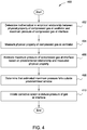
- Figure 4 is a flow diagram of method steps for determining the maximum pressure of compressed gas delivered to a user via an interface.
- a method 400 begins at step 402, where control logic 102 within ventilator 100 determines a mathematical or empirical relationship between a measurable quantity of compressed gas output by mechanical components 106 and the maximum pressure of compressed gas at interface 120.
- control logic 102 may receive data indicating the mathematical relationship, such as an equation that relates the measurable quantity to the maximum pressure.
- control logic 102 receives data that reflects a mapping, such as a look-up table, indicating a correspondence between empirical measurements of the measurable quantity and empirical measurements of the maximum pressure.
- control logic 102 receives a mathematical relationship that is derived to fit empirical data.
- the measurable quantity of the compressed gas may be any attribute of the compressed gas that can be detected by sensor 104, including a mass flow rate associated with the compressed gas or a lumen pressure associated with that compressed gas, among others.
- sensor 104 within ventilator 100 measures the measurable quantity of the compressed gas exiting mechanical components 106.
- the measurable quantity may be, among others, a mass flow rate, as described above in conjunction with Figures 1 and 3A , or a lumen pressure, as described above in conjunction with Figures 1 and 3B .
- control logic 102 estimates the maximum pressure of the compressed gas at interface 120 based on the relationship established at step 402 and the measurable quantity measured at step 404. In embodiments where control logic 102 relies on a mathematical relationship, control logic 102 may compute the output of the mathematical relationship as a function of the measured quantity. In embodiments where control logic 102 relies on an empirical mapping, control logic 102 may retrieve an estimated maximum pressure value from the empirical mapping based on the measured quantity. The accuracy of either such relationship may depend on the presence of plenum 220 and/or inlet discs 210 shown in Figure 2A-2B , and/or venturi device 124 shown in Figures 1 and 2C .
- control logic 102 determines that the maximum pressure estimated at step 406 departs from a predefined window of acceptable pressures.
- the threshold value generally reflects a pressure limit beyond which usage of interface 120 may be unsafe for user 130.
- control logic 102 initiates corrective action to adjust the pressure of the compressed gas at interface 120. In doing so, control logic 102 may alert user 130 that the ventilator pressure should be reduced or increased, or may actively reduce or increase the ventilator pressure without user intervention. The method 400 then ends.
- a ventilator is configured to assist a user with breathing, while eliminating the need for extraneous sensors and tubing normally found in prior art ventilators.
- the ventilator relies on a predetermined relationship between a measurable quantity associated with a compressed gas and the maximum pressure of that compressed gas upon delivery to the user.
- the measurable quantity may be mass flow rate of the compressed gas or pressure within a delivery lumen used to transport the compressed gas, among others.
- the ventilator determines whether the pressure of compressed gas delivered to the user exceeds a maximum allowable pressure. When the maximum pressure is exceeded, the ventilator initiates corrective action to reduce the pressure of the compressed gas.
- At least one advantage of the various designs and techniques set forth herein is that the disclosed ventilator does not require additional pressure transducers or extra lumen in order to accurately determine the pressure of compressed gas delivered to the user, thereby reducing the cost and complexity of the ventilator as a whole.
- the disclosed interface does not require extraneous sensing components, the overall size and weight of the interface can be reduced, potentially increasing comfort for the user. Accordingly, the disclosed ventilator can be safely used with a low-profile nasal interfaces, further increasing comfort for the user.
Claims (10)
- Ventilateur configuré pour estimer la pression d'un gaz à l'intérieur d'une interface, comprenant :une logique de commande (102) configurée pour déterminer une première relation entre une quantité mesurable associée au gaz et la pression du gaz à l'intérieur de l'interface, l'interface étant disposée au niveau d'une sortie (240) d'un dispositif venturi (124) ; etun capteur (104) configuré pour générer au niveau d'un premier emplacement une première mesure de la quantité mesurable associée au gaz sortant d'un ou de plusieurs composants mécaniques (106), le premier emplacement étant situé entre les un ou plusieurs composants mécaniques et une entrée (230) du dispositif venturi, la logique de commande recevant la première mesure et estimant la pression du gaz à l'intérieur de l'interface sur la base de la première relation et de la première mesure.
- Système configuré pour estimer la pression d'un gaz à l'intérieur d'une interface, comprenant :un ventilateur selon la revendication 1 ; etl'interface, couplée au ventilateur et configurée pour distribuer la première quantité de gaz à un utilisateur.
- Système selon la revendication 2, où l'interface inclut :un plénum, couplé de façon fluidique au ventilateur et configuré pour tamponner le gaz à mesure que le gaz entre dans l'interface ; etau moins un disque de sortie couplé au plénum et configuré pour permettre au gaz de s'échapper du plénum pour une distribution à l'utilisateur.
- Système selon la revendication 3, où le plénum est configuré pour tamponner le gaz afin d'égaliser des variations de pression à mesure que le gaz entre dans l'interface.
- Système selon la revendication 4, où la logique de commande est configurée pour estimer la pression du gaz à l'intérieur de l'interface avec une précision qui dépend de l'égalisation des variations de pression à mesure que le gaz entre dans l'interface.
- Système selon la revendication 3, où l'au moins un disque de sortie inclut une pluralité de trous de sortie à travers lesquels le gaz tamponné s'échappe pour la distribution à l'utilisateur.
- Système selon la revendication 2, où la quantité mesurable comprend un débit massique ou une valeur de pression de lumière associée au gaz lors de la sortie du ventilateur.
- Système selon la revendication 2, dans lequel la logique de commande est configurée pour déterminer que la pression estimée n'est pas dans une fenêtre de pressions prédéfinie, et, en réponse, pour lancer une action corrective, l'action corrective comprenant l'ajustement de la pression du gaz à l'intérieur de l'interface ou l'alerte d'un utilisateur de l'interface que la pression du gaz devrait être réduite.
- Système selon la revendication 2, où la quantité mesurable comprend un débit massique associée au gaz lors de la sortie du ventilateur.
- Système selon la revendication 2, où la quantité mesurable comprend une valeur de pression de lumière associée au gaz lors de la sortie d'un ventilateur.
Applications Claiming Priority (2)
| Application Number | Priority Date | Filing Date | Title |
|---|---|---|---|
| US201361893000P | 2013-10-18 | 2013-10-18 | |
| PCT/US2014/061147 WO2015058089A1 (fr) | 2013-10-18 | 2014-10-17 | Techniques pour déterminer une pression de voies aériennes d'un patient |
Publications (3)
| Publication Number | Publication Date |
|---|---|
| EP3057636A1 EP3057636A1 (fr) | 2016-08-24 |
| EP3057636A4 EP3057636A4 (fr) | 2017-06-14 |
| EP3057636B1 true EP3057636B1 (fr) | 2021-11-17 |
Family
ID=52825079
Family Applications (1)
| Application Number | Title | Priority Date | Filing Date |
|---|---|---|---|
| EP14853470.4A Active EP3057636B1 (fr) | 2013-10-18 | 2014-10-17 | Dispositif et système pour déterminer une pression de voies aériennes d'un patient |
Country Status (3)
| Country | Link |
|---|---|
| US (2) | US9995645B2 (fr) |
| EP (1) | EP3057636B1 (fr) |
| WO (1) | WO2015058089A1 (fr) |
Families Citing this family (13)
| Publication number | Priority date | Publication date | Assignee | Title |
|---|---|---|---|---|
| DE102004006396B4 (de) * | 2004-02-10 | 2021-11-04 | Löwenstein Medical Technology S.A. | Vorrichtung zur Beatmung sowie Verfahren zur Steuerung eines Beatmungsgerätes |
| US7954490B2 (en) | 2005-02-09 | 2011-06-07 | Vbox, Incorporated | Method of providing ambulatory oxygen |
| US9669172B2 (en) * | 2012-07-05 | 2017-06-06 | Resmed Limited | Discreet respiratory therapy system |
| US9995645B2 (en) * | 2013-10-18 | 2018-06-12 | Silverbow Development, Llc | Techniques for determining patient airway pressure |
| US11278698B2 (en) * | 2014-03-04 | 2022-03-22 | Koninklijke Philips N.V. | Blending gas enriched pressure support system and method |
| US20180177960A1 (en) * | 2014-03-21 | 2018-06-28 | Fisher & Paykel Healthcare Limited | Sensing arrangement for gas delivery system |
| US11642486B2 (en) | 2019-05-17 | 2023-05-09 | Breathe Technologies, Inc. | Portable oxygen concentrator retrofit system and method |
| US11607519B2 (en) | 2019-05-22 | 2023-03-21 | Breathe Technologies, Inc. | O2 concentrator with sieve bed bypass and control method thereof |
| US11207486B2 (en) * | 2020-05-29 | 2021-12-28 | Legacy US Inc. | Fluid mixing apparatus such as a ventilator |
| US11738165B2 (en) | 2020-05-29 | 2023-08-29 | Legacy US Inc. | Fluid mixing apparatus such as a ventilator |
| US11420007B2 (en) | 2020-08-05 | 2022-08-23 | Effortless Oxygen, Llc | Flow triggered gas delivery |
| US11318276B2 (en) | 2020-08-05 | 2022-05-03 | Effortless Oxygen, Llc | Flow triggered gas delivery |
| US11247008B1 (en) | 2020-08-05 | 2022-02-15 | Effortless Oxygen, Llc | Flow triggered gas delivery |
Family Cites Families (29)
| Publication number | Priority date | Publication date | Assignee | Title |
|---|---|---|---|---|
| FR2250541A1 (en) * | 1973-11-08 | 1975-06-06 | Masson Yves Le | Positive pressure respiratory equipment - has oxygen nozzle in venturi supplying second venturi determining pressure |
| US5551419A (en) * | 1994-12-15 | 1996-09-03 | Devilbiss Health Care, Inc. | Control for CPAP apparatus |
| US6544192B2 (en) * | 1998-02-25 | 2003-04-08 | Respironics, Inc. | Patient monitor and method of using same |
| US6478026B1 (en) * | 1999-03-13 | 2002-11-12 | Thomas J. Wood | Nasal ventilation interface |
| US7987847B2 (en) * | 2000-12-29 | 2011-08-02 | Resmed Limited | Characterisation of mask systems |
| DE10105383C2 (de) | 2001-02-06 | 2003-06-05 | Heptec Gmbh | Antischnarchgerät |
| AU2003245018A1 (en) * | 2002-07-22 | 2004-02-09 | Hasdi Matarasso | A respiratory aid apparatus and method |
| US20060180149A1 (en) | 2003-07-22 | 2006-08-17 | Hasdi Matarasso | A respiratory aid system and method |
| AU2008203812B2 (en) * | 2007-08-17 | 2014-10-02 | ResMed Pty Ltd | Methods and Apparatus for Pressure Therapy in the Treatment of Sleep Disordered Breathing |
| EP2106818B1 (fr) * | 2008-03-31 | 2013-12-25 | Nellcor Puritan Bennett Llc | Système de compensation pour une chute de pression dans un système d'assistance respiratoire |
| US8302602B2 (en) * | 2008-09-30 | 2012-11-06 | Nellcor Puritan Bennett Llc | Breathing assistance system with multiple pressure sensors |
| WO2010115170A2 (fr) * | 2009-04-02 | 2010-10-07 | Breathe Technologies, Inc. | Procédés, systèmes et dispositifs de ventilation ouverte peu vulnérante pour traiter des obstructions des voies aériennes |
| CN102413861B (zh) * | 2009-04-24 | 2014-10-22 | 纽约大学 | 用于允许持续气道正压通气提供零压的回路的系统和方法 |
| CA2774902C (fr) | 2009-09-03 | 2017-01-03 | Breathe Technologies, Inc. | Procedes, systemes et dispositifs de ventilation non invasive comprenant une interface de ventilation non etanche avec orifice d'entrainement et/ou element de pression |
| EP2329768A1 (fr) * | 2009-12-02 | 2011-06-08 | Srett | Surveillance de respiration |
| CN103052420B (zh) | 2010-05-22 | 2015-07-15 | 马奎特紧急护理公司 | 具有流量估算的呼吸系统 |
| WO2012014106A1 (fr) | 2010-07-27 | 2012-02-02 | Koninklijke Philips Electronics N.V. | Estimation de fuites à l'aide d'une estimation de fonction |
| EP2646098B1 (fr) * | 2010-12-03 | 2018-07-25 | Fisher & Paykel Healthcare Limited | Système, appareil et procédés d'approvisionnement en gaz |
| FR2971930B1 (fr) * | 2011-02-24 | 2014-02-28 | Air Liquide | Appareil de suivi de l'observance d'un traitement de l'apnee obstructive du sommeil |
| US8714154B2 (en) * | 2011-03-30 | 2014-05-06 | Covidien Lp | Systems and methods for automatic adjustment of ventilator settings |
| US9616194B2 (en) * | 2011-06-22 | 2017-04-11 | Breathe Technologies, Inc. | Ventilation mask with integrated piloted exhalation valve and method of ventilating a patient using the same |
| CN107569759A (zh) * | 2011-11-11 | 2018-01-12 | 瑞思迈有限公司 | 用于呼吸治疗的交换器组件 |
| US9669172B2 (en) * | 2012-07-05 | 2017-06-06 | Resmed Limited | Discreet respiratory therapy system |
| WO2014042862A1 (fr) * | 2012-09-12 | 2014-03-20 | Silverbow Development Llc | Appareil et systèmes d'interface nasale destinés à être utilisés avec un dispositif d'assistance respiratoire |
| WO2014057457A2 (fr) * | 2012-10-10 | 2014-04-17 | Koninklijke Philips N.V. | Compensation adaptative de circuit de patient à capteur de pression au niveau d'un appareil à masque |
| US20140144441A1 (en) | 2012-11-28 | 2014-05-29 | L'Air Liquide, Société Anonyme pour I'Etude et I'Exploitation des Procédés Georges Claude | Dosimetric therapeutic gas delivery method for rapid dosimetry adjustment and optimization |
| US9833584B2 (en) * | 2013-03-22 | 2017-12-05 | Breathe Technologies, Inc. | Portable ventilator secretion management system |
| US9566407B2 (en) * | 2013-06-28 | 2017-02-14 | L'Air Liquide, Société Anonyme pour l'Etude et l'Exploitation des Procédés Georges Claude | Nasal cannula assembly with flow control passage communicating with a deformable reservoir |
| US9995645B2 (en) * | 2013-10-18 | 2018-06-12 | Silverbow Development, Llc | Techniques for determining patient airway pressure |
-
2014
- 2014-10-17 US US14/517,186 patent/US9995645B2/en active Active
- 2014-10-17 EP EP14853470.4A patent/EP3057636B1/fr active Active
- 2014-10-17 WO PCT/US2014/061147 patent/WO2015058089A1/fr active Application Filing
-
2018
- 2018-06-12 US US16/006,699 patent/US10859456B2/en active Active
Non-Patent Citations (1)
| Title |
|---|
| None * |
Also Published As
| Publication number | Publication date |
|---|---|
| US9995645B2 (en) | 2018-06-12 |
| EP3057636A1 (fr) | 2016-08-24 |
| US20180364119A1 (en) | 2018-12-20 |
| EP3057636A4 (fr) | 2017-06-14 |
| WO2015058089A1 (fr) | 2015-04-23 |
| US10859456B2 (en) | 2020-12-08 |
| US20150107592A1 (en) | 2015-04-23 |
Similar Documents
| Publication | Publication Date | Title |
|---|---|---|
| US10859456B2 (en) | Techniques for determining patient airway pressure | |
| US11833297B2 (en) | Methods and systems for adaptive base flow and leak compensation | |
| US11717626B2 (en) | Automated control for detection of flow limitation | |
| AU2010343682B2 (en) | Automatically controlled ventilation system | |
| US10543327B2 (en) | Methods and systems for adaptive base flow | |
| JP5199082B2 (ja) | 呼吸用気体測定装置 | |
| US9925346B2 (en) | Systems and methods for ventilation with unknown exhalation flow | |
| EP3229880B1 (fr) | Appareil de détection de défaillance dans l'administration d'oxygène | |
| EP3229884B1 (fr) | Système de distribution de débit variable d'oxygène | |
| EP2643040B1 (fr) | Système et procédé de traitement du syndrome d'hypoventilation de l'obésité | |
| US20130012828A1 (en) | Method and System for Measuring Nasal Resistance to Airflow | |
| WO2013033419A1 (fr) | Procédés et systèmes de réglage du volume courant pendant une ventilation | |
| CN110114105B (zh) | 确定患者回路中的变化的压力支持设备和方法 | |
| US9272111B2 (en) | Leak estimation using function estimation | |
| EP3316949B1 (fr) | Capteur de pression barométrique pour compensation de circuit de dispositif de ventilation spontanée en pression positive à résistance variable | |
| CN111760140B (zh) | 呼吸器及其控制方法 | |
| US11191917B2 (en) | Pressure support device and method of providing an alert for non-effective pressure compensation regimen | |
| WO2020136035A1 (fr) | Système de soutien de pression et procédé d'administration d'une thérapie par soutien de pression à un patient | |
| EP2846861B1 (fr) | Systèmes de détermination de la fraction d'oxygène inspiré pendant la ventilation | |
| US20120053481A1 (en) | Method and system for measuring nasal resistance to airflow |
Legal Events
| Date | Code | Title | Description |
|---|---|---|---|
| PUAI | Public reference made under article 153(3) epc to a published international application that has entered the european phase |
Free format text: ORIGINAL CODE: 0009012 |
|
| 17P | Request for examination filed |
Effective date: 20160518 |
|
| AK | Designated contracting states |
Kind code of ref document: A1 Designated state(s): AL AT BE BG CH CY CZ DE DK EE ES FI FR GB GR HR HU IE IS IT LI LT LU LV MC MK MT NL NO PL PT RO RS SE SI SK SM TR |
|
| AX | Request for extension of the european patent |
Extension state: BA ME |
|
| DAX | Request for extension of the european patent (deleted) | ||
| A4 | Supplementary search report drawn up and despatched |
Effective date: 20170512 |
|
| RIC1 | Information provided on ipc code assigned before grant |
Ipc: A61M 16/08 20060101ALN20170508BHEP Ipc: A61M 16/12 20060101ALI20170508BHEP Ipc: A61M 16/20 20060101ALI20170508BHEP Ipc: A61M 16/00 20060101AFI20170508BHEP Ipc: A61M 16/06 20060101ALI20170508BHEP |
|
| RAP1 | Party data changed (applicant data changed or rights of an application transferred) |
Owner name: SILVERBOW DEVELOPMENT LLC |
|
| STAA | Information on the status of an ep patent application or granted ep patent |
Free format text: STATUS: EXAMINATION IS IN PROGRESS |
|
| 17Q | First examination report despatched |
Effective date: 20190410 |
|
| STAA | Information on the status of an ep patent application or granted ep patent |
Free format text: STATUS: EXAMINATION IS IN PROGRESS |
|
| RAP1 | Party data changed (applicant data changed or rights of an application transferred) |
Owner name: INOGEN, INC. |
|
| GRAP | Despatch of communication of intention to grant a patent |
Free format text: ORIGINAL CODE: EPIDOSNIGR1 |
|
| STAA | Information on the status of an ep patent application or granted ep patent |
Free format text: STATUS: GRANT OF PATENT IS INTENDED |
|
| INTG | Intention to grant announced |
Effective date: 20210615 |
|
| GRAS | Grant fee paid |
Free format text: ORIGINAL CODE: EPIDOSNIGR3 |
|
| GRAA | (expected) grant |
Free format text: ORIGINAL CODE: 0009210 |
|
| STAA | Information on the status of an ep patent application or granted ep patent |
Free format text: STATUS: THE PATENT HAS BEEN GRANTED |
|
| RAP3 | Party data changed (applicant data changed or rights of an application transferred) |
Owner name: INOGEN, INC. |
|
| AK | Designated contracting states |
Kind code of ref document: B1 Designated state(s): AL AT BE BG CH CY CZ DE DK EE ES FI FR GB GR HR HU IE IS IT LI LT LU LV MC MK MT NL NO PL PT RO RS SE SI SK SM TR |
|
| REG | Reference to a national code |
Ref country code: GB Ref legal event code: FG4D |
|
| REG | Reference to a national code |
Ref country code: IE Ref legal event code: FG4D |
|
| REG | Reference to a national code |
Ref country code: DE Ref legal event code: R096 Ref document number: 602014081349 Country of ref document: DE |
|
| REG | Reference to a national code |
Ref country code: AT Ref legal event code: REF Ref document number: 1447536 Country of ref document: AT Kind code of ref document: T Effective date: 20211215 |
|
| REG | Reference to a national code |
Ref country code: LT Ref legal event code: MG9D |
|
| REG | Reference to a national code |
Ref country code: NL Ref legal event code: MP Effective date: 20211117 |
|
| REG | Reference to a national code |
Ref country code: AT Ref legal event code: MK05 Ref document number: 1447536 Country of ref document: AT Kind code of ref document: T Effective date: 20211117 |
|
| PG25 | Lapsed in a contracting state [announced via postgrant information from national office to epo] |
Ref country code: RS Free format text: LAPSE BECAUSE OF FAILURE TO SUBMIT A TRANSLATION OF THE DESCRIPTION OR TO PAY THE FEE WITHIN THE PRESCRIBED TIME-LIMIT Effective date: 20211117 Ref country code: LT Free format text: LAPSE BECAUSE OF FAILURE TO SUBMIT A TRANSLATION OF THE DESCRIPTION OR TO PAY THE FEE WITHIN THE PRESCRIBED TIME-LIMIT Effective date: 20211117 Ref country code: FI Free format text: LAPSE BECAUSE OF FAILURE TO SUBMIT A TRANSLATION OF THE DESCRIPTION OR TO PAY THE FEE WITHIN THE PRESCRIBED TIME-LIMIT Effective date: 20211117 Ref country code: BG Free format text: LAPSE BECAUSE OF FAILURE TO SUBMIT A TRANSLATION OF THE DESCRIPTION OR TO PAY THE FEE WITHIN THE PRESCRIBED TIME-LIMIT Effective date: 20220217 Ref country code: AT Free format text: LAPSE BECAUSE OF FAILURE TO SUBMIT A TRANSLATION OF THE DESCRIPTION OR TO PAY THE FEE WITHIN THE PRESCRIBED TIME-LIMIT Effective date: 20211117 |
|
| PG25 | Lapsed in a contracting state [announced via postgrant information from national office to epo] |
Ref country code: IS Free format text: LAPSE BECAUSE OF FAILURE TO SUBMIT A TRANSLATION OF THE DESCRIPTION OR TO PAY THE FEE WITHIN THE PRESCRIBED TIME-LIMIT Effective date: 20220317 Ref country code: SE Free format text: LAPSE BECAUSE OF FAILURE TO SUBMIT A TRANSLATION OF THE DESCRIPTION OR TO PAY THE FEE WITHIN THE PRESCRIBED TIME-LIMIT Effective date: 20211117 Ref country code: PT Free format text: LAPSE BECAUSE OF FAILURE TO SUBMIT A TRANSLATION OF THE DESCRIPTION OR TO PAY THE FEE WITHIN THE PRESCRIBED TIME-LIMIT Effective date: 20220317 Ref country code: PL Free format text: LAPSE BECAUSE OF FAILURE TO SUBMIT A TRANSLATION OF THE DESCRIPTION OR TO PAY THE FEE WITHIN THE PRESCRIBED TIME-LIMIT Effective date: 20211117 Ref country code: NO Free format text: LAPSE BECAUSE OF FAILURE TO SUBMIT A TRANSLATION OF THE DESCRIPTION OR TO PAY THE FEE WITHIN THE PRESCRIBED TIME-LIMIT Effective date: 20220217 Ref country code: NL Free format text: LAPSE BECAUSE OF FAILURE TO SUBMIT A TRANSLATION OF THE DESCRIPTION OR TO PAY THE FEE WITHIN THE PRESCRIBED TIME-LIMIT Effective date: 20211117 Ref country code: LV Free format text: LAPSE BECAUSE OF FAILURE TO SUBMIT A TRANSLATION OF THE DESCRIPTION OR TO PAY THE FEE WITHIN THE PRESCRIBED TIME-LIMIT Effective date: 20211117 Ref country code: HR Free format text: LAPSE BECAUSE OF FAILURE TO SUBMIT A TRANSLATION OF THE DESCRIPTION OR TO PAY THE FEE WITHIN THE PRESCRIBED TIME-LIMIT Effective date: 20211117 Ref country code: GR Free format text: LAPSE BECAUSE OF FAILURE TO SUBMIT A TRANSLATION OF THE DESCRIPTION OR TO PAY THE FEE WITHIN THE PRESCRIBED TIME-LIMIT Effective date: 20220218 Ref country code: ES Free format text: LAPSE BECAUSE OF FAILURE TO SUBMIT A TRANSLATION OF THE DESCRIPTION OR TO PAY THE FEE WITHIN THE PRESCRIBED TIME-LIMIT Effective date: 20211117 |
|
| PG25 | Lapsed in a contracting state [announced via postgrant information from national office to epo] |
Ref country code: SM Free format text: LAPSE BECAUSE OF FAILURE TO SUBMIT A TRANSLATION OF THE DESCRIPTION OR TO PAY THE FEE WITHIN THE PRESCRIBED TIME-LIMIT Effective date: 20211117 Ref country code: SK Free format text: LAPSE BECAUSE OF FAILURE TO SUBMIT A TRANSLATION OF THE DESCRIPTION OR TO PAY THE FEE WITHIN THE PRESCRIBED TIME-LIMIT Effective date: 20211117 Ref country code: RO Free format text: LAPSE BECAUSE OF FAILURE TO SUBMIT A TRANSLATION OF THE DESCRIPTION OR TO PAY THE FEE WITHIN THE PRESCRIBED TIME-LIMIT Effective date: 20211117 Ref country code: EE Free format text: LAPSE BECAUSE OF FAILURE TO SUBMIT A TRANSLATION OF THE DESCRIPTION OR TO PAY THE FEE WITHIN THE PRESCRIBED TIME-LIMIT Effective date: 20211117 Ref country code: DK Free format text: LAPSE BECAUSE OF FAILURE TO SUBMIT A TRANSLATION OF THE DESCRIPTION OR TO PAY THE FEE WITHIN THE PRESCRIBED TIME-LIMIT Effective date: 20211117 Ref country code: CZ Free format text: LAPSE BECAUSE OF FAILURE TO SUBMIT A TRANSLATION OF THE DESCRIPTION OR TO PAY THE FEE WITHIN THE PRESCRIBED TIME-LIMIT Effective date: 20211117 |
|
| REG | Reference to a national code |
Ref country code: DE Ref legal event code: R097 Ref document number: 602014081349 Country of ref document: DE |
|
| PLBE | No opposition filed within time limit |
Free format text: ORIGINAL CODE: 0009261 |
|
| STAA | Information on the status of an ep patent application or granted ep patent |
Free format text: STATUS: NO OPPOSITION FILED WITHIN TIME LIMIT |
|
| 26N | No opposition filed |
Effective date: 20220818 |
|
| PG25 | Lapsed in a contracting state [announced via postgrant information from national office to epo] |
Ref country code: AL Free format text: LAPSE BECAUSE OF FAILURE TO SUBMIT A TRANSLATION OF THE DESCRIPTION OR TO PAY THE FEE WITHIN THE PRESCRIBED TIME-LIMIT Effective date: 20211117 |
|
| PG25 | Lapsed in a contracting state [announced via postgrant information from national office to epo] |
Ref country code: SI Free format text: LAPSE BECAUSE OF FAILURE TO SUBMIT A TRANSLATION OF THE DESCRIPTION OR TO PAY THE FEE WITHIN THE PRESCRIBED TIME-LIMIT Effective date: 20211117 |
|
| PG25 | Lapsed in a contracting state [announced via postgrant information from national office to epo] |
Ref country code: MC Free format text: LAPSE BECAUSE OF FAILURE TO SUBMIT A TRANSLATION OF THE DESCRIPTION OR TO PAY THE FEE WITHIN THE PRESCRIBED TIME-LIMIT Effective date: 20211117 Ref country code: IT Free format text: LAPSE BECAUSE OF FAILURE TO SUBMIT A TRANSLATION OF THE DESCRIPTION OR TO PAY THE FEE WITHIN THE PRESCRIBED TIME-LIMIT Effective date: 20211117 |
|
| REG | Reference to a national code |
Ref country code: CH Ref legal event code: PL |
|
| REG | Reference to a national code |
Ref country code: BE Ref legal event code: MM Effective date: 20221031 |
|
| PG25 | Lapsed in a contracting state [announced via postgrant information from national office to epo] |
Ref country code: LU Free format text: LAPSE BECAUSE OF NON-PAYMENT OF DUE FEES Effective date: 20221017 |
|
| P01 | Opt-out of the competence of the unified patent court (upc) registered |
Effective date: 20230530 |
|
| PG25 | Lapsed in a contracting state [announced via postgrant information from national office to epo] |
Ref country code: LI Free format text: LAPSE BECAUSE OF NON-PAYMENT OF DUE FEES Effective date: 20221031 Ref country code: CH Free format text: LAPSE BECAUSE OF NON-PAYMENT OF DUE FEES Effective date: 20221031 |
|
| PG25 | Lapsed in a contracting state [announced via postgrant information from national office to epo] |
Ref country code: BE Free format text: LAPSE BECAUSE OF NON-PAYMENT OF DUE FEES Effective date: 20221031 |
|
| PG25 | Lapsed in a contracting state [announced via postgrant information from national office to epo] |
Ref country code: IE Free format text: LAPSE BECAUSE OF NON-PAYMENT OF DUE FEES Effective date: 20221017 |
|
| PGFP | Annual fee paid to national office [announced via postgrant information from national office to epo] |
Ref country code: GB Payment date: 20230831 Year of fee payment: 10 |
|
| PGFP | Annual fee paid to national office [announced via postgrant information from national office to epo] |
Ref country code: FR Payment date: 20230911 Year of fee payment: 10 |
|
| PGFP | Annual fee paid to national office [announced via postgrant information from national office to epo] |
Ref country code: DE Payment date: 20230830 Year of fee payment: 10 |
|
| PG25 | Lapsed in a contracting state [announced via postgrant information from national office to epo] |
Ref country code: HU Free format text: LAPSE BECAUSE OF FAILURE TO SUBMIT A TRANSLATION OF THE DESCRIPTION OR TO PAY THE FEE WITHIN THE PRESCRIBED TIME-LIMIT; INVALID AB INITIO Effective date: 20141017 |