EP1355080A1 - Outer shell unit and method of manufacturing the unit - Google Patents
Outer shell unit and method of manufacturing the unit Download PDFInfo
- Publication number
- EP1355080A1 EP1355080A1 EP01272330A EP01272330A EP1355080A1 EP 1355080 A1 EP1355080 A1 EP 1355080A1 EP 01272330 A EP01272330 A EP 01272330A EP 01272330 A EP01272330 A EP 01272330A EP 1355080 A1 EP1355080 A1 EP 1355080A1
- Authority
- EP
- European Patent Office
- Prior art keywords
- outer shell
- welding
- unit
- knuckle
- torch
- Prior art date
- Legal status (The legal status is an assumption and is not a legal conclusion. Google has not performed a legal analysis and makes no representation as to the accuracy of the status listed.)
- Granted
Links
Images








Classifications
-
- B—PERFORMING OPERATIONS; TRANSPORTING
- B21—MECHANICAL METAL-WORKING WITHOUT ESSENTIALLY REMOVING MATERIAL; PUNCHING METAL
- B21D—WORKING OR PROCESSING OF SHEET METAL OR METAL TUBES, RODS OR PROFILES WITHOUT ESSENTIALLY REMOVING MATERIAL; PUNCHING METAL
- B21D41/00—Application of procedures in order to alter the diameter of tube ends
- B21D41/04—Reducing; Closing
- B21D41/045—Closing
-
- B—PERFORMING OPERATIONS; TRANSPORTING
- B21—MECHANICAL METAL-WORKING WITHOUT ESSENTIALLY REMOVING MATERIAL; PUNCHING METAL
- B21D—WORKING OR PROCESSING OF SHEET METAL OR METAL TUBES, RODS OR PROFILES WITHOUT ESSENTIALLY REMOVING MATERIAL; PUNCHING METAL
- B21D17/00—Forming single grooves in sheet metal or tubular or hollow articles
- B21D17/02—Forming single grooves in sheet metal or tubular or hollow articles by pressing
-
- B—PERFORMING OPERATIONS; TRANSPORTING
- B21—MECHANICAL METAL-WORKING WITHOUT ESSENTIALLY REMOVING MATERIAL; PUNCHING METAL
- B21K—MAKING FORGED OR PRESSED METAL PRODUCTS, e.g. HORSE-SHOES, RIVETS, BOLTS OR WHEELS
- B21K1/00—Making machine elements
- B21K1/06—Making machine elements axles or shafts
- B21K1/12—Making machine elements axles or shafts of specially-shaped cross-section
-
- B—PERFORMING OPERATIONS; TRANSPORTING
- B21—MECHANICAL METAL-WORKING WITHOUT ESSENTIALLY REMOVING MATERIAL; PUNCHING METAL
- B21K—MAKING FORGED OR PRESSED METAL PRODUCTS, e.g. HORSE-SHOES, RIVETS, BOLTS OR WHEELS
- B21K21/00—Making hollow articles not covered by a single preceding sub-group
- B21K21/12—Shaping end portions of hollow articles
-
- B—PERFORMING OPERATIONS; TRANSPORTING
- B21—MECHANICAL METAL-WORKING WITHOUT ESSENTIALLY REMOVING MATERIAL; PUNCHING METAL
- B21K—MAKING FORGED OR PRESSED METAL PRODUCTS, e.g. HORSE-SHOES, RIVETS, BOLTS OR WHEELS
- B21K21/00—Making hollow articles not covered by a single preceding sub-group
- B21K21/12—Shaping end portions of hollow articles
- B21K21/14—Shaping end portions of hollow articles closed or substantially-closed ends, e.g. cartridge bottoms
-
- B—PERFORMING OPERATIONS; TRANSPORTING
- B23—MACHINE TOOLS; METAL-WORKING NOT OTHERWISE PROVIDED FOR
- B23K—SOLDERING OR UNSOLDERING; WELDING; CLADDING OR PLATING BY SOLDERING OR WELDING; CUTTING BY APPLYING HEAT LOCALLY, e.g. FLAME CUTTING; WORKING BY LASER BEAM
- B23K31/00—Processes relevant to this subclass, specially adapted for particular articles or purposes, but not covered by any single one of main groups B23K1/00 - B23K28/00
- B23K31/02—Processes relevant to this subclass, specially adapted for particular articles or purposes, but not covered by any single one of main groups B23K1/00 - B23K28/00 relating to soldering or welding
-
- B—PERFORMING OPERATIONS; TRANSPORTING
- B60—VEHICLES IN GENERAL
- B60G—VEHICLE SUSPENSION ARRANGEMENTS
- B60G13/00—Resilient suspensions characterised by arrangement, location or type of vibration dampers
-
- B—PERFORMING OPERATIONS; TRANSPORTING
- B60—VEHICLES IN GENERAL
- B60G—VEHICLE SUSPENSION ARRANGEMENTS
- B60G13/00—Resilient suspensions characterised by arrangement, location or type of vibration dampers
- B60G13/001—Arrangements for attachment of dampers
- B60G13/005—Arrangements for attachment of dampers characterised by the mounting on the axle or suspension arm of the damper unit
- B60G13/006—Arrangements for attachment of dampers characterised by the mounting on the axle or suspension arm of the damper unit on the stub axle
-
- B—PERFORMING OPERATIONS; TRANSPORTING
- B60—VEHICLES IN GENERAL
- B60G—VEHICLE SUSPENSION ARRANGEMENTS
- B60G15/00—Resilient suspensions characterised by arrangement, location or type of combined spring and vibration damper, e.g. telescopic type
- B60G15/02—Resilient suspensions characterised by arrangement, location or type of combined spring and vibration damper, e.g. telescopic type having mechanical spring
- B60G15/06—Resilient suspensions characterised by arrangement, location or type of combined spring and vibration damper, e.g. telescopic type having mechanical spring and fluid damper
- B60G15/062—Resilient suspensions characterised by arrangement, location or type of combined spring and vibration damper, e.g. telescopic type having mechanical spring and fluid damper the spring being arranged around the damper
- B60G15/063—Resilient suspensions characterised by arrangement, location or type of combined spring and vibration damper, e.g. telescopic type having mechanical spring and fluid damper the spring being arranged around the damper characterised by the mounting of the spring on the damper
-
- B—PERFORMING OPERATIONS; TRANSPORTING
- B60—VEHICLES IN GENERAL
- B60G—VEHICLE SUSPENSION ARRANGEMENTS
- B60G15/00—Resilient suspensions characterised by arrangement, location or type of combined spring and vibration damper, e.g. telescopic type
- B60G15/02—Resilient suspensions characterised by arrangement, location or type of combined spring and vibration damper, e.g. telescopic type having mechanical spring
- B60G15/06—Resilient suspensions characterised by arrangement, location or type of combined spring and vibration damper, e.g. telescopic type having mechanical spring and fluid damper
- B60G15/07—Resilient suspensions characterised by arrangement, location or type of combined spring and vibration damper, e.g. telescopic type having mechanical spring and fluid damper the damper being connected to the stub axle and the spring being arranged around the damper
-
- F—MECHANICAL ENGINEERING; LIGHTING; HEATING; WEAPONS; BLASTING
- F16—ENGINEERING ELEMENTS AND UNITS; GENERAL MEASURES FOR PRODUCING AND MAINTAINING EFFECTIVE FUNCTIONING OF MACHINES OR INSTALLATIONS; THERMAL INSULATION IN GENERAL
- F16F—SPRINGS; SHOCK-ABSORBERS; MEANS FOR DAMPING VIBRATION
- F16F9/00—Springs, vibration-dampers, shock-absorbers, or similarly-constructed movement-dampers using a fluid or the equivalent as damping medium
- F16F9/32—Details
- F16F9/3207—Constructional features
- F16F9/3235—Constructional features of cylinders
-
- B—PERFORMING OPERATIONS; TRANSPORTING
- B23—MACHINE TOOLS; METAL-WORKING NOT OTHERWISE PROVIDED FOR
- B23K—SOLDERING OR UNSOLDERING; WELDING; CLADDING OR PLATING BY SOLDERING OR WELDING; CUTTING BY APPLYING HEAT LOCALLY, e.g. FLAME CUTTING; WORKING BY LASER BEAM
- B23K2101/00—Articles made by soldering, welding or cutting
- B23K2101/04—Tubular or hollow articles
- B23K2101/12—Vessels
-
- B—PERFORMING OPERATIONS; TRANSPORTING
- B60—VEHICLES IN GENERAL
- B60G—VEHICLE SUSPENSION ARRANGEMENTS
- B60G2202/00—Indexing codes relating to the type of spring, damper or actuator
- B60G2202/20—Type of damper
- B60G2202/24—Fluid damper
-
- B—PERFORMING OPERATIONS; TRANSPORTING
- B60—VEHICLES IN GENERAL
- B60G—VEHICLE SUSPENSION ARRANGEMENTS
- B60G2202/00—Indexing codes relating to the type of spring, damper or actuator
- B60G2202/30—Spring/Damper and/or actuator Units
- B60G2202/31—Spring/Damper and/or actuator Units with the spring arranged around the damper, e.g. MacPherson strut
- B60G2202/312—The spring being a wound spring
-
- B—PERFORMING OPERATIONS; TRANSPORTING
- B60—VEHICLES IN GENERAL
- B60G—VEHICLE SUSPENSION ARRANGEMENTS
- B60G2204/00—Indexing codes related to suspensions per se or to auxiliary parts
- B60G2204/10—Mounting of suspension elements
- B60G2204/12—Mounting of springs or dampers
- B60G2204/124—Mounting of coil springs
- B60G2204/1242—Mounting of coil springs on a damper, e.g. MacPerson strut
-
- B—PERFORMING OPERATIONS; TRANSPORTING
- B60—VEHICLES IN GENERAL
- B60G—VEHICLE SUSPENSION ARRANGEMENTS
- B60G2204/00—Indexing codes related to suspensions per se or to auxiliary parts
- B60G2204/10—Mounting of suspension elements
- B60G2204/12—Mounting of springs or dampers
- B60G2204/124—Mounting of coil springs
- B60G2204/1242—Mounting of coil springs on a damper, e.g. MacPerson strut
- B60G2204/12422—Mounting of coil springs on a damper, e.g. MacPerson strut anchoring the end coils on the spring support plate
-
- B—PERFORMING OPERATIONS; TRANSPORTING
- B60—VEHICLES IN GENERAL
- B60G—VEHICLE SUSPENSION ARRANGEMENTS
- B60G2204/00—Indexing codes related to suspensions per se or to auxiliary parts
- B60G2204/10—Mounting of suspension elements
- B60G2204/12—Mounting of springs or dampers
- B60G2204/129—Damper mount on wheel suspension or knuckle
-
- B—PERFORMING OPERATIONS; TRANSPORTING
- B60—VEHICLES IN GENERAL
- B60G—VEHICLE SUSPENSION ARRANGEMENTS
- B60G2204/00—Indexing codes related to suspensions per se or to auxiliary parts
- B60G2204/40—Auxiliary suspension parts; Adjustment of suspensions
- B60G2204/43—Fittings, brackets or knuckles
-
- B—PERFORMING OPERATIONS; TRANSPORTING
- B60—VEHICLES IN GENERAL
- B60G—VEHICLE SUSPENSION ARRANGEMENTS
- B60G2204/00—Indexing codes related to suspensions per se or to auxiliary parts
- B60G2204/40—Auxiliary suspension parts; Adjustment of suspensions
- B60G2204/43—Fittings, brackets or knuckles
- B60G2204/4304—Bracket for lower cylinder mount of McPherson strut
-
- B—PERFORMING OPERATIONS; TRANSPORTING
- B60—VEHICLES IN GENERAL
- B60G—VEHICLE SUSPENSION ARRANGEMENTS
- B60G2206/00—Indexing codes related to the manufacturing of suspensions: constructional features, the materials used, procedures or tools
- B60G2206/01—Constructional features of suspension elements, e.g. arms, dampers, springs
- B60G2206/40—Constructional features of dampers and/or springs
- B60G2206/41—Dampers
-
- B—PERFORMING OPERATIONS; TRANSPORTING
- B60—VEHICLES IN GENERAL
- B60G—VEHICLE SUSPENSION ARRANGEMENTS
- B60G2206/00—Indexing codes related to the manufacturing of suspensions: constructional features, the materials used, procedures or tools
- B60G2206/01—Constructional features of suspension elements, e.g. arms, dampers, springs
- B60G2206/50—Constructional features of wheel supports or knuckles, e.g. steering knuckles, spindle attachments
-
- B—PERFORMING OPERATIONS; TRANSPORTING
- B60—VEHICLES IN GENERAL
- B60G—VEHICLE SUSPENSION ARRANGEMENTS
- B60G2206/00—Indexing codes related to the manufacturing of suspensions: constructional features, the materials used, procedures or tools
- B60G2206/01—Constructional features of suspension elements, e.g. arms, dampers, springs
- B60G2206/80—Manufacturing procedures
- B60G2206/81—Shaping
-
- B—PERFORMING OPERATIONS; TRANSPORTING
- B60—VEHICLES IN GENERAL
- B60G—VEHICLE SUSPENSION ARRANGEMENTS
- B60G2206/00—Indexing codes related to the manufacturing of suspensions: constructional features, the materials used, procedures or tools
- B60G2206/01—Constructional features of suspension elements, e.g. arms, dampers, springs
- B60G2206/80—Manufacturing procedures
- B60G2206/82—Joining
- B60G2206/8201—Joining by welding
Definitions
- This invention relates to an outer shell unit provided with a shock absorber which absorbs vibration or impacts.
- this invention relates to a structure and a method of manufacture therefore as applied to an outer shell unit provided with a strut-type shock absorber in the suspension system of a vehicle.
- strut-type shock absorbers in the suspension system of a vehicle also play a role as a structural member positioning the vehicle wheels as a component in the suspension member.
- FIG. 16 shows a prior-art example of a strut-type shock absorber 1.
- the outer side of this shock absorber 1 is provided with an outer shell unit 10 storing a damping force generating mechanism.
- the outer shell unit 10 is provided with a cylindrical outer shell 3, a spring guide 6 mounted by welding onto the outer shell 3 and supporting a suspension spring and a knuckle bracket 7 mounted by welding on the outer shell 3 and connected to a knuckle.
- the knuckle bracket 7 is fixed by welding after press-fitting onto the outer shell 3.
- the upper and lower ends 7e, 7f of a single-plate type of knuckle bracket 7 are respectively fixed to the outer shell 3 by welding.
- Inlays 32, 37 are formed by a mechanical process on both ends of the outer shell 3.
- a rod guide 9 is mounted on the upper end of the inlay 32.
- a lower cap 17 is mounted on the lower end of the inlay 37. The outer peripheral section of the lower cap 17 is welded to the lower end of the outer shell 3 together with the lower end 7f of the knuckle bracket 7 and the bottom of the outer shell 3 is sealed.
- the outer shell 3 is rotated about the substantially perpendicular center axis O when welding the upper end 7e of the knuckle bracket 7 to the outer shell 3.
- a flat welding technique is employed in which the torch 61 of the arc-welding unit is oriented downwardly towards the corner between the outer peripheral face 3a of the outer shell 3 and the upper end 7e of the knuckle bracket 7.
- the shape of the welded section is in the form of a lap weld with a partial fillet weld.
- the outer shell 3 is rotated about the center axis O which is inclined through an angle of 60 degrees with respect to the horizontal plane.
- a flat welding technique is employed in which the torch 61 of the arc-welding unit is oriented downwards towards the corner between the lower end 3b of the outer shell 3, the lower end 7f of the knuckle bracket 7 and the lower cap 17.
- the shape of the welded section has a specific shape comprising a characteristic flare, a lap weld and a partial fillet weld. Consequently highly accurate welding techniques and considerable welding time is required.
- the lower end 6a of the spring guide 6 is welded simultaneously with the above at three positions to the outer peripheral face 3a of the outer shell 3.
- the shape of this welded section is in the form of a lap weld.
- the assembly line process for the outer shell 3 comprises the steps in 1 ⁇ 2 ⁇ 3 ⁇ 4 ⁇ 5 ⁇ 6 ⁇ 7 ⁇ as shown in FIG. 19 and FIG. 20.
- the welding line for the outer shell unit 10 comprises the steps in 1 ⁇ 2 ⁇ 3 ⁇ 4 ⁇ 5 ⁇ 6 ⁇ 7 ⁇ 8 ⁇ as shown in FIG. 20.
- This invention increases productivity by reducing the number cutting operations on an inlay and the number of processes for assembling the lower cap by forming a bottom using a closing process.
- This invention provides a protrusion projecting from the bottom of the outer shell in order to ensure sealing characteristics of the bottom. Furthermore the structure is simplified since it is possible to directly engage the knuckle with the outer shell by providing a threaded section in the protrusion.
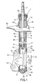
- FIG. 1 shows a cross section of a shock absorber.
- This strut-type shock absorber 1 is provided with a rod 2 connected to the vehicle body, an outer shell 3 connected to the knuckle (not shown) which supports the vehicle shaft, a rod guide 9 which supports the rod 2 to slide freely on the outer shell 3, an inner tube 4 which partitions an oil storage chamber 18 with gas enclosed in a section on the inner side of the outer shell 3, a piston 5 which is connected to the tip of the rod 2 and which partitions the inner section of the inner tube 4 into an upper oil chamber 16 and a lower oil chamber 17, a piston valve 11 which generates a damping force during an extension stroke and a base valve generating a damping force during a compression stroke.
- the shock absorber 1 comprises a damping force generating mechanism in the outer shell 3 for damping vibrations on the vehicle wheels.
- the strut-type shock absorber 1 is provided with a spring guide 6 supporting the lower end of a suspension spring and a knuckle bracket 7 connected to the knuckle.
- the shock absorber 1 plays the role of positioning the vehicle wheels by acting as a section of a suspension member.
- An annular step 35 is formed by extrusion molding with a blister process along the outer shell 3.
- the spring guide 6 is fixed by press fitting to the step 35. In this manner, it is not necessary to weld the spring guide 6 to the outer peripheral face 3a of the outer shell 3.
- FIG. 2 shows a process for forming a step 35 using a blister operation.
- the blister operation unit comprises a jig 52 retaining a work 41 such as a pipe member, an outer mold 53 encircling the outer side of a work 41, an inner mold 54 disposed on the inner side of a work 41 and a wedge-shaped engaging member 55 which displaces the inner mold 54 in a radial direction.
- a work 41 retained on the jig 52 is encircled by the outer mold 53, the inner mold 54 is disposed on the inner side of the work 41 and the engaging member 56 is pressed by a force P onto the inner mold 54.
- the inner mold 54 expands radially and a step 35 is formed by the resulting swelling along the work 41 in an annular shape corresponding to the shape of the outer mold 53 and the inner mold 54.
- the spring guide 6 has an engaging section 6a which engages with the outer shell 3 and a sheet 6b which supports the lower end of the suspension spring.
- the spring guide 6 is integrated by a pressing operation.
- the outer shell 3 has a cylindrical main body 30 and a bottom 31 which covers the lower end of the main body 30.
- the bottom 31 of the outer shell 3 is integrated to the main body 30 of the outer shell 3 by a molding process termed a closing process. In this manner, the sealing characteristics of the bottom 31 of the outer shell 3 can be maintained and it is therefore not required to seal the bottom 31 by welding.
- FIG. 3 shows the process of forming a bottom 31 using a closing process.
- the device used in the closing process comprises a chuck 42 retaining a work 41 such as a pipe member, a cored bar 44 disposed coaxially with respect to the work 41 by a retaining bar 43 on the inner side of the work 41, a die 45 rotating about a shaft having a predetermined offset S from the work 41 and a heating coil 46 heating the die 43.
- the work 41, the cored bar 44 and the die 45 are rotated in the same direction.
- the die 45 has an inner peripheral face 45a formed in a concave cylindrical shape and a curved face 45b formed in a substantially concave spherical shape.
- the cored bar 44 has a cylindrical outer peripheral face 44a, a curved face 44b projecting substantially in the shape of a sphere and an indentation 44c provided in the center of the curved face 44b.
- the closing process is such that the open end of the work 41 between the die 45 and the cored bar 44 is gradually constricted by pressing the die 45 onto the work 41 with a force P while rotating the work 41, the cored bar 44 and the die 45 in the same direction.
- the bottom 31 is formed closing and sealing the opening into a conical cylinder.
- the bottom 31 inclines with an angle ⁇ with respect to a face which is orthogonal to the central axis O.
- the angle ⁇ is set for example to 30 degrees ( ⁇ /6rad).
- the central section of the bottom 31 is closed by constricting the work 41 between the die 45 and the cored bar 44. During this operation, a protrusion 34 is formed on the work 41 and projects into the indentation 44c of the cored bar 44. Consequently it is possible to ensure sealing of the bottom 31 by providing a protrusion 34 which projects into the outer shell 3 from the bottom 31.
- the knuckle bracket 7 comprises an engaging section 7a which engages with the outer shell 3, a pair of flanges 7b which sandwich the knuckle, and a hose bracket 7g.
- Bolt holes 7c, 7d are formed on each flange 7b.
- a knuckle is fixed to the knuckle bracket 7 by two bolts inserted into the bolt holes 7c, 7d. In order to ensure dimensional accuracy, both bolt holes 7c, 7d undergo a drilling operation after the knuckle bracket 7 is fixed by welding to the outer shell 3.
- the knuckle bracket 7 is a single-plate type which is not provided with a reinforcing member between the flanges 7b.
- the knuckle bracket 7 is fixed by welding after being press-fitted to the outer shell 3. It is possible to perform a smooth press-fitting operation on the outer shell 3 since the lower end of the outer shell 3 is drawn into a tapering shape using a closing process.
- the upper and lower ends 7e, 7f of the single-plate type knuckle bracket 7 are fixed to the outer shell 3 by respective welded sections 21, 22
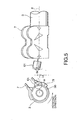
- welded section 21 on the upper side of the bracket is welded using a vertical downward welding method with the torch 61 of the arc-welding unit oriented towards the corner between the outer peripheral face 3a of the outer shell 3 and the upper end 7e of the knuckle bracket 7.
- the outer shell 3 is rotated about the central axis O which is disposed in a substantially horizontal plane.
- the torch 61 of the arc-welding unit is oriented to the lateral section of the outer shell 3.
- the direction in which the outer shell 3 is rotated is set to a direction in which the position of the outer shell 3 facing the torch 61 rises as shown by the arrow in FIG. 4(b).
- the horizontal plane including the central axis O of the outer shell 3 is taken to be a horizontal reference plane X.
- the vertical plane including the central axis O of the outer shell 3 is taken to be a horizontal reference plane Y.
- the welding point W is defined by the intersection of a line extended from the torch 61 of the arc-welding unit with the outer peripheral face 3a of the outer shell 3.
- the welding point W is either offset onto the horizontal reference plane X or to a position above the horizontal reference plane X by a predetermined length Lx.
- the outer radius of the outer shell 3 is approximately 45mm and the offset amount Lx is set in the range 0-10mm.
- the welding point W is offset from the vertical reference plane Y by a predetermined length Ly.
- the vertical downward welding method is performing by disposing the welding point W so that the vertical offset amount Lx is smaller than the horizontal offset amount Ly.
- the torch angle ⁇ x of the torch 61 is inclined upwardly with respect to the horizontal reference plane X and is set to be smaller than the torch angle ⁇ y inclined with respect to the vertical reference plane Y.
- the torch angle ⁇ x is set to the range 0 - 30degrees (0 - ⁇ /Grad).
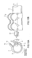
- the welded section 21 on the lower side of the bracket is welded using a vertical downward welding method with the torch 61 of the arc-welding unit oriented towards the corner between the lower end 3b of the outer shell 3 and the lower end 7f of the knuckle bracket 7.
- the outer shell 3 is rotated about the central axis O which is disposed in a substantially horizontal plane.
- the direction in which the outer shell 3 is rotated is set to a direction in which the position of the outer shell 3 facing the torch 61 rises as shown by the arrow in FIG. 5(a).
- the welding point W is either offset onto the horizontal reference line X or to a position above the horizontal reference plane X by a predetermined length Lx.
- the outer radius of the outer shell 3 is approximately 45mm and the offset amount Lx is set in the range 0 -10mm.
- the torch angle ⁇ x of the torch 61 is inclined upwardly with respect to the horizontal reference plane X is set to be smaller than the torch angle ⁇ y inclined with respect to the vertical reference plane Y In this embodiment, the torch angle ⁇ x is set to the range 0 - 15degrees (0 - ⁇ /12rad).
- the vertical downward welding method allows arbitrary setting of the offset amount Lx, the torch angle ⁇ x, as well as the rotation speed of the outer shell 3, the voltage and the current of the torch in response to the outer radius of the outer shell 3.
- a welding speed is obtained which is greater than that obtained by a welding device using a conventional flat welding method since a balance is produced between the welding speed and the drip rate of the flux.
- FIG. 6 shows the relationship between the torch angle ⁇ x and the spatter fall amount.
- the arc force is applied on the flux as shown by the arrow in the drawing and presses the flux in a forward direction.
- the torch angle ⁇ x is set above 30 degrees, the amount of spatter fall increases rapidly.
- the bead width increases. Although this results in an improvement to the outward appearance, it also tends to result in insufficient fusion or failure of fusion. Consequently the bead line may become indented and reduce insufficient component strength. Insufficient fusion may result in an excessive leading edge in the flux and create an arc-shaped residue over the flux.
- a torch angle ⁇ x set in a range of 0 - 30degrees allows the spatter fall amount to be suppressed and thus effectively suppresses insufficient fusion or failure of fusion.
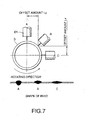
- FIG. 7 shows the general relationship of bead shape and the offset amount Lx, Ly of the welding point W.
- the offset amount Lx decreases, the drip rate of the flux increases and the bead width increases. Conversely as the offset amount Lx increases, the drip rate of the flux decreases and the bead width narrows.
- the rotation speed of the outer shell 3 is increased, the balance with respect to the drip rate for the flux fails and faults may result in the welding process.
- the offset amount Lx of the welding point W with respect to the horizontal reference plane X is set to increase as the outer radius of the outer shell 3 increases.
- the offset amount Lx is set in a range of 0 - 10mm, a suitable drip rate for the flux is obtained and improved bead formation characteristics are obtained.
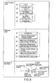
- FIG. 8 shows the process of manufacturing an outer shell unit 10 comprising a spring guide 6, a knuckle bracket 7 and an outer shell 3.
- the production line manufacturing the outer shell unit 10 is separated into a processing line for the outer shell 3 which processes the outer shell 3, and a welding line for the outer shell unit 10 which mounts the spring guide 6 and the knuckle bracket 7 onto the outer shell 3.
- the turnover rate required to form a single outer shell 3 in the processing line is made equal to the turnover rate required to form a single outer shell unit 10 in the welding line.
- the processing line process for the outer shell 3 comprises the sequence of the process in 1 ⁇ 2 ⁇ 3 ⁇ 4 ⁇ 5 ⁇ as shown in FIG. 8 and FIG. 9.
- the welding line for the outer shell unit 10 comprises the steps in 1 ⁇ 2 ⁇ 3 ⁇ 4 ⁇ 5 ⁇ 6 ⁇ 7 ⁇ as shown in FIG. 8.
- the turnover rate required to form a single outer shell 3 in the processing line is made equal to the turnover rate required to form a single outer shell unit 10 in the welding line.
- the spring guide 6 is press fitted to the outer shell 3 and welding operations on both components are omitted. Furthermore the upper and lower ends 7e, 7f of the knuckle bracket 7 are high-speed welded using a vertical downward welding method on the outer shell 3. Thus it is possible to shorten the cycle time required to form a single outer shell unit 10 in the welding line.
- the knuckle bracket 7 may be a cylindrical double-plate type in which a reinforcing member 15 may be provided between each flange 7b.
- the reinforcing member 15 is fixed between the flanges 7b in order to increase the rigidity of the knuckle bracket 7.
- a vertical downward welding method is used with the torch 61 of the arc-welding unit oriented towards the corner between the lower end 3b of the outer shell 3 and the lower end 7f of the knuckle bracket 7.
- the outer shell 3 is rotated about the central axis O disposed in a substantially horizontal plane.
- the direction in which the outer shell 3 is rotated is set to a direction in which the position of the outer shell 3 facing the torch 61 rises as shown by the arrow in FIG. 10(a).
- the welding point W is either offset onto the horizontal reference plane X or to a position above the horizontal reference plane X by a predetermined length Lx.
- the outer radius of the outer shell 3 is approximately 45mm and the offset amount Lx is set in the range 0 - 10mm.
- the torch angle ⁇ x of the torch 61 is inclined upwardly with respect to the horizontal reference plane X and is set to the range 0 - 30 degrees (0 - ⁇ /6 rad).
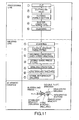
- FIG. 11 shows the process of manufacturing an outer shell unit 10.
- the production line is separated into a processing line for the outer shell 3 which processes the outer shell 3, and a welding line for the outer shell unit 10 which mounts the spring guide 6 and the knuckle bracket 7 onto the outer shell 3.
- a processing line for the outer shell 3 which processes the outer shell 3
- a welding line for the outer shell unit 10 which mounts the spring guide 6 and the knuckle bracket 7 onto the outer shell 3.
- the processing line for the outer shell 3 comprises the steps in 1 ⁇ 2 ⁇ 3 ⁇ 4 ⁇ 5 ⁇ as shown in FIG. 11. This is the same as the processing line shown in FIG. 8.
- the welding line for the outer shell unit 10 comprises the steps in 1 ⁇ 2 ⁇ 3 ⁇ 4 ⁇ 5 ⁇ 6 ⁇ 7 ⁇ as shown in FIG. 11.
- this welding line adds the step of welding the stabilizer bracket 16 to the outer shell 3 and omits the step of high-speed welding of the upper end 7e of the knuckle bracket 7 to the outer peripheral face 3a of the outer shell 3 using a vertical downward welding method.
- Using a cylindrical double-plate knuckle bracket 7 allows the stabilizer bracket 16 to be welded to the outer shell 3 in the same cycle time as that taken in the processing line. This is due to the fact that it is not necessary to fit the upper end 7e of the knuckle bracket 7 to the outer shell 3 by welding.
- FIG. 12(a), (b), (c) Another embodiment is shown in FIG. 12(a), (b), (c).
- the step 35 formed by a blister operation on the outer shell 3 is omitted and the spring guide 6 may be fixed by welding to the outer peripheral face 3a of the outer shell 3.
- a cylindrical double-plate knuckle bracket 7 may be provided which has a reinforcing member 15 between each flange 7b.
- the lower end 6c of the knuckle bracket 7 is welded to the outer peripheral face 3a of the outer shell 3.
- a high-speed welding operation comprising a downward welding method is used is used to weld the spring guide 6 to the outer peripheral face 3a of the outer shell 3.
- the torch 61 of the arc-welding unit is oriented towards the corner between the outer peripheral face 3a of the outer shell 3 and the lower end 6c of the spring guide 6.
- the outer shell 3 is rotated about the central axis O which is disposed in a substantially horizontal plane.
- the direction in which the outer shell 3 is rotated is set to a direction in which the position of the outer shell 3 facing the torch 61 rises as shown by the arrow in FIG. 12(a).
- the welding point W is either offset onto the horizontal reference plane X or to a position above the horizontal reference plane X by a predetermined length Lx.
- the outer radius of the outer shell 3 is approximately 45mm and the offset amount Lx is set in the range 0 - 10mm.
- the torch angle ⁇ x of the torch 61 is inclined upwardly with respect to the horizontal reference plane X and is set to the range 0 - 15 degrees (0 - ⁇ /12rad).
- FIG. 13 shows the process of manufacturing an outer shell unit 10.
- the production line is separated into a processing line for the outer shell 3 which processes the outer shell 3, and a welding line for the outer shell unit 10 which mounts the spring guide 6 and the knuckle bracket 7 onto the outer shell 3.
- the cycle time of both lines is made equal.
- the processing line for the outer shell 3 comprises the steps in 1 ⁇ 2 ⁇ 3 ⁇ 4 ⁇ .
- the processing line omits the process of forming the step 35 with the blister process along the work 41.
- the welding line for the outer shell unit 10 comprises the steps in 1 ⁇ 2 ⁇ 3 ⁇ 4 ⁇ 5 ⁇ 6 ⁇ 7 ⁇
- the processing line adds the step of welding the stabilizer bracket 16 to the outer shell 3 and the step of welding the spring guide 6 to the outer shell 3 and omits the step of high-speed welding of the upper end 7e of the knuckle bracket 7 to the outer peripheral face 3a of the outer shell 3 and omits the step of press-fitting the spring guide 6 to the outer shell 3.
- Using a cylindrical double-plate knuckle bracket 7 allows the stabilizer bracket 16 and the spring guide 6 to be welded to the outer shell 3 in the same cycle time as that taken in the processing line since it is not necessary to fit the upper end 7e of the knuckle bracket 7 to the outer shell 3 by welding.
- the process of stamping a number or an identification sign of the component on the work 41 may be performed in the processing line.
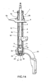
- a knuckle 20 supporting the vehicle shaft may be directly fixed to the outer shell 3.
- the knuckle 20 has the function of positioning the vehicle wheel as a section of a suspension member.
- the knuckle 20 has an engagement hole 21 which is engaged with the outer shell 3 from below.
- the outer shell 3 has a cylindrical main body 30 and a tapering section (a knuckle mounting section) engaging the engaging hole 21 of the knuckle 20 with the lower end of the main body 30.
- the tapering section 34 is inclined to taper downwardly and is engaged in the engaging hole 21 of the knuckle 20 which inclines in the same manner.
- the outer shell 3 has a bottom 31 covering the lower end of the main body 30 and a threaded section 35 projecting from the bottom 31.
- the threaded section 36 projects downwardly through the engagement hole 21 of the knuckle 20.
- a washer 23 and a nut 22 are provided.
- the washer 23 acts as a fixing member which is inserted into the threaded section 36 and abuts with the lower end face of the engagement hole 21 of the knuckle 20.
- the nut 22 acts as a fixing member which is threadably engaged with the threaded section 36.
- the engagement hole 21 of the knuckle 20 is engaged with the tapering section 34 of the outer shell 3 and fixed through the washer 23 by the nut 22 which is threadably engaged with the threaded section 36.
- the protrusion 33 comprises a bottom 31, a threaded section 36 and a tapering section 34 of the outer shell 3.
- the protrusion 33 is integrated with the main body 30 of the outer shell 3 by a molding process termed a closing process. In this manner, the sealing characteristics of the bottom 31 of the outer shell 3 are ensured and it is not required to seal the bottom 31 by welding.
- FIG. 15 shows the process of forming a protrusion 33, a bottom 31 and a tapering section 34 using the closing process.
- the closing processing unit comprises a chuck 42 retaining a work 41 such as a pipe member, a cored bar 44 disposed coaxially with respect to the work 41 by a retaining bar 43 on the inner side of the work 41, a die 45 rotating about a shaft having a predetermined offset S from the work 41 and a heating coil 46 heating the die 43.
- the work 41, the cored bar 44 and the die 45 are rotated in the same direction.
- the die 45 has a cylindrical tapering face 45a formed in a concave tapering shape and a cylindrical inner peripheral face 45c formed in the center of a curved face 45b.
- the cored bar 44 has a cylindrical outer peripheral face 44a, a curved face 44b projecting substantially in the shape of a sphere and an indentation 44c provided in the center of the curved face 44b.
- the closing process is such that the open end of the work 41 between the die 45 and the cored bar 44 is gradually constricted by pressing the die 45 onto the work 41 with a force P while rotating the work 41, the cored bar 44 and the die 45 in the same direction.
- the bottom 31 is formed closing and sealing the opening into a conical cylinder.
- the central section of the bottom 31 is closed by constricting the work 41 between the die 45 and the cored bar 44. During this operation, the protrusion 33 is formed to project into the indentation 45c of the die 45 on the work 41.
- Threading is engraved onto the protrusion 33 by a mechanical process in order to form the threaded section 36.
- the knuckle 20 is engaged to the tapering section 34 of the outer shell 3 and is fixed by a nut 22 which is threadably engaged to the threaded section 36.
- the cycle time can be shortened and productivity can be thereby increased since the welding process in the prior-art example in which the knuckle bracket is welded onto the outer shell can be omitted.
- An annular step projecting from the outer peripheral face of the outer shell 3 may be formed as a knuckle mounting section which is inserted into the engagement hole 21 of the knuckle in the outer shell 3. Furthermore a member fixed between the nut 22 and the bottom 31 of the outer shell 3 may be formed in the knuckle 20.
- the outer shell unit and the method of manufacture therefore according to this invention is related to a shock absorber which damps vibration and shocks.
- the invention relates to an application to a strut-type shock absorber in a vehicle suspension system.
Landscapes
- Engineering & Computer Science (AREA)
- Mechanical Engineering (AREA)
- General Engineering & Computer Science (AREA)
- Vehicle Body Suspensions (AREA)
- Butt Welding And Welding Of Specific Article (AREA)
- Fluid-Damping Devices (AREA)
Abstract
Description
Claims (14)
- A method of manufacturing an outer shell unit provided with a cylindrical outer shell housing a damping force generating mechanism and a knuckle bracket mounted on the outer shell to connect a knuckle, the method comprising the steps of;forming a bottom of the outer shell using a closing process, andwelding the knuckle bracket to the outer shell after forming the bottom.
- The method of manufacturing an outer shell unit as defined in Claim 1, wherein a vertical downward welding method is used to weld the lower end of the knuckle bracket to the outer shell.
- The method of manufacturing an outer shell unit as defined in Claim 1, wherein a protrusion projecting from the bottom of the outer shell is formed by a closing process.
- The method of manufacturing an outer shell unit as defined in Claim 1, further comprising the steps of;mounting a spring guide on the outer shell to support a suspension spring,forming a step by a blister process along the outer shell, andmounting the spring guide by press-fitting on the step.
- The method of producing an outer shell unit of Claim 1, wherein a spring guide mounted on the outer shell to support a suspension spring, the method comprising the steps of;wherein the cycle time for forming one outer shell in the processing line is made substantially equal to the cycle time for welding one outer shell unit in the welding line.providing a processing line for the outer shell to form an outer shell from a pipe member using a mechanical process, andproviding a welding line for the outer shell unit to mount a knuckle bracket and a spring guide on an outer shell,
- The method of producing an outer shell unit as defined in Claim 5, wherein a cylindrical double-plate knuckle bracket is mounted on the outer shell in the welding line and one end of the knuckle bracket is welded by a vertical downward welding method to the outer shell.
- A method of welding an outer shell unit comprising a cylindrical outer shell housing a damping force generating mechanism and a suspension component welded to the outer shell, the method comprising the steps of;disposing a torch of the arc-welding unit in proximity to the welding position of a suspension component and the side of the outer shell, andwelding the suspension component to the outer shell by rotating the outer shell unit so that the welded position facing the torch rises.
- The method of welding an outer shell unit as defined in Claim 7,
wherein the horizontal plane including the central axis O of the outer shell is taken to be a horizontal reference plane X,
the point at which a line extended from the torch intersects with the outer shell unit is taken to be the welding point W, and
the welding point W is either offset in order to be on the horizontal reference plane X or to be above the horizontal reference plane by a length Lx. - The method of welding an outer shell unit as defined in Claim 8,
wherein
the vertical plane including the central axis O of the outer shell is taken to be a vertical reference plane Y,
the welding point W is offset to be above the vertical reference plane Y by a length Ly, and
the vertical offset Lx being smaller than the horizontal offset amount Ly. - The method of welding an outer shell unit as defined in Claim 7,
wherein
the horizontal plane including the central axis O of the outer shell is taken to be a horizontal reference plane X,
the torch has a torch angle x inclined upwardly with respect to the horizontal reference plane X, and
the torch angle x being set in a range of 0 - 30 degrees. - An outer shell unit comprising;a cylindrical outer shell housing a damping force generating mechanism, anda knuckle bracket mounted on the outer shell to connect a knuckle,
whereinthe bottom of the outer shell is formed by a closing process, andthe knuckle bracket is fixed to the outer shell by welding. - An outer shell unit comprising;a cylindrical outer shell housing a damping force generating mechanism, anda suspension component welded to the outer shell, whereinthe torch of the arc-welding unit is disposed in proximity to the welded position of the suspension component and the side of the outer shell, andthe suspension component is welded to the outer shell by rotating the outer shell so that the welded position which faces the torch rises.
- An outer shell unit comprising;a cylindrical outer shell housing a damping force generating mechanism,a knuckle mounting section provided in an engagement hole of the knuckle into which the outer shell is inserted in order to mount the outer shell on the knuckle, anda threaded section which projects downwardly through the engagement hole of the knuckle from the bottom of the outer shell.
- The outer shell unit as defined in Claim 13, wherein a protrusion which projects from the bottom of the outer shell is formed by a closing process; and
a threaded section is formed on the protrusion.
Applications Claiming Priority (9)
| Application Number | Priority Date | Filing Date | Title |
|---|---|---|---|
| JP2000394715 | 2000-12-26 | ||
| JP2000394698A JP4729170B2 (en) | 2000-12-26 | 2000-12-26 | Strut type outer shell unit and manufacturing method thereof |
| JP2000394698 | 2000-12-26 | ||
| JP2000394722A JP2002195331A (en) | 2000-12-26 | 2000-12-26 | Strut type shock absorber |
| JP2000394722 | 2000-12-26 | ||
| JP2000394715A JP4851646B2 (en) | 2000-12-26 | 2000-12-26 | Production method of strut type outer shell unit |
| JP2001014369 | 2001-01-23 | ||
| JP2001014369A JP4740463B2 (en) | 2001-01-23 | 2001-01-23 | Outer shell unit and welding method thereof |
| PCT/JP2001/011456 WO2002052166A1 (en) | 2000-12-26 | 2001-12-26 | Outer shell unit and method of manufacturing the unit |
Publications (3)
| Publication Number | Publication Date |
|---|---|
| EP1355080A1 true EP1355080A1 (en) | 2003-10-22 |
| EP1355080A4 EP1355080A4 (en) | 2008-05-21 |
| EP1355080B1 EP1355080B1 (en) | 2010-07-14 |
Family
ID=27481917
Family Applications (1)
| Application Number | Title | Priority Date | Filing Date |
|---|---|---|---|
| EP01272330A Expired - Lifetime EP1355080B1 (en) | 2000-12-26 | 2001-12-26 | Methods of manufacturing an outer shell unit |
Country Status (5)
| Country | Link |
|---|---|
| US (1) | US7022932B2 (en) |
| EP (1) | EP1355080B1 (en) |
| DE (1) | DE60142580D1 (en) |
| ES (1) | ES2346512T3 (en) |
| WO (1) | WO2002052166A1 (en) |
Cited By (11)
| Publication number | Priority date | Publication date | Assignee | Title |
|---|---|---|---|---|
| EP1867406A4 (en) * | 2005-03-31 | 2012-02-15 | Kayaba Industry Co Ltd | CLOSURE METHOD AND CLOSING MACHINE |
| EP1870178A4 (en) * | 2005-03-31 | 2012-02-22 | Kayaba Industry Co Ltd | METHOD AND DEVICE FOR PACKING |
| EP1867405A4 (en) * | 2005-03-31 | 2012-02-22 | Kayaba Industry Co Ltd | CLOSURE METHOD AND CLOSING MACHINE |
| EP1867404A4 (en) * | 2005-03-31 | 2012-03-07 | Kayaba Industry Co Ltd | CLOSURE METHOD AND CLOSING MACHINE |
| RU173134U1 (en) * | 2016-09-14 | 2017-08-14 | Общество с ограниченной ответственностью "Первоуральский Автоагрегатный завод" | HYDRAULIC SHOCK ABSORBER |
| RU176229U1 (en) * | 2016-11-17 | 2018-01-12 | Общество с ограниченной ответственностью "Первоуральский Автоагрегатный завод" | BOTTOM RESERVOIR OF A HYDRAULIC SHOCK ABSORBER |
| RU176338U1 (en) * | 2016-11-17 | 2018-01-17 | Общество с ограниченной ответственностью "Первоуральский Автоагрегатный завод" | TANK OF A HYDRAULIC SHOCK ABSORBER |
| RU177253U1 (en) * | 2016-11-09 | 2018-02-14 | Общество с ограниченной ответственностью "Первоуральский Автоагрегатный завод" | Hydraulic shock absorber |
| CN107952897A (en) * | 2017-12-06 | 2018-04-24 | 贵州华阳电工有限公司 | Closing in positioner with internal thread housing |
| RU189695U1 (en) * | 2019-01-10 | 2019-05-30 | Открытое акционерное общество "Барановичский автоагрегатный завод" | HYDRAULIC DAMPER |
| RU196018U1 (en) * | 2019-06-11 | 2020-02-13 | Общество С Ограниченной Ответственностью "Научно-Производственное Объединение "Ростар" | SHOCK RESERVOIR TANK |
Families Citing this family (17)
| Publication number | Priority date | Publication date | Assignee | Title |
|---|---|---|---|---|
| JP4836478B2 (en) | 2005-03-31 | 2011-12-14 | カヤバ工業株式会社 | Closing processing method and closing processing machine |
| JP4721748B2 (en) * | 2005-03-31 | 2011-07-13 | カヤバ工業株式会社 | Closing processing method and closing processing machine |
| JP4663582B2 (en) * | 2006-05-30 | 2011-04-06 | カヤバ工業株式会社 | Strut type shock absorber |
| EP2818055B1 (en) | 2007-12-05 | 2020-10-28 | N.V. Nutricia | High energy liquid enteral nutritional composition |
| WO2009113845A1 (en) | 2008-03-12 | 2009-09-17 | N.V. Nutricia | High protein liquid enteral nutritional composition |
| US20100219172A1 (en) * | 2009-03-02 | 2010-09-02 | Air Liquide Industrial U.S. Lp | Process For Reducing The Loss Of Backing Gas When Welding Pipe |
| CN102601262A (en) * | 2012-03-31 | 2012-07-25 | 富奥汽车零部件股份有限公司 | Shock absorber oil storage tank machining method, shock absorber oil storage tank machining device and shock absorber oil storage tank |
| JP6082295B2 (en) * | 2013-03-26 | 2017-02-15 | Kyb株式会社 | Knuckle bracket, pair of knuckle bracket, and suspension manufacturing method |
| DE102013205468B4 (en) | 2013-03-27 | 2014-12-24 | Zf Friedrichshafen Ag | Method for producing a contact section for fastening a further component to a cylinder tube for a vibration damper |
| JP6043230B2 (en) * | 2013-04-10 | 2016-12-14 | Kyb株式会社 | Manufacturing apparatus and manufacturing method for knuckle bracket |
| CN105020318A (en) * | 2015-07-09 | 2015-11-04 | 重庆川东减震制造有限公司 | Oil storage barrel assembly |
| US10850584B2 (en) * | 2016-06-07 | 2020-12-01 | Beijingwest Industries Co., Ltd. | Damper housing and a method for manufacturing the damper housing |
| CN107263046B (en) * | 2017-06-02 | 2019-06-14 | 珠海格力电器股份有限公司 | Installation mechanism and air conditioner processing device with same |
| CN109772939B (en) * | 2019-02-28 | 2021-03-26 | 航天材料及工艺研究所 | A kind of small diameter superalloy annular closed cavity structure rounding method and device |
| JP7502976B2 (en) * | 2020-11-25 | 2024-06-19 | カヤバ株式会社 | Shock absorber |
| WO2023149152A1 (en) * | 2022-02-03 | 2023-08-10 | 日立Astemo株式会社 | Shock absorber and bracket |
| CN119927076B (en) * | 2025-04-07 | 2025-06-27 | 云南益华管道科技有限公司 | Annular corrugated pipe flaring mechanism |
Family Cites Families (18)
| Publication number | Priority date | Publication date | Assignee | Title |
|---|---|---|---|---|
| US2421629A (en) * | 1943-02-10 | 1947-06-03 | Otto A Langos | Method for closing the ends of metal tubes |
| US2671348A (en) * | 1951-08-31 | 1954-03-09 | Adamson Stephens Mfg Co | Live shaft idler pulley |
| JPS5353530Y1 (en) * | 1969-03-13 | 1978-12-21 | ||
| JPS5353530A (en) | 1976-10-25 | 1978-05-16 | Fuji Electronics Co Ltd | Surface treating method of metallic products by glow dischrage |
| US4168795A (en) * | 1978-01-09 | 1979-09-25 | General Electric Company | Method of welding a projecting bracket to a tank or the like |
| JPS5545524A (en) * | 1978-09-26 | 1980-03-31 | Babcock Hitachi Kk | Two electrode welding method of pipe |
| US4884665A (en) * | 1985-12-24 | 1989-12-05 | Ford Motor Company | Automotive shock absorber with unitary striker plate and closure cap |
| JPH05131233A (en) * | 1991-10-29 | 1993-05-28 | Atsugi Unisia Corp | Molding method for closing pipe end |
| JPH0858330A (en) * | 1994-08-25 | 1996-03-05 | Toyota Motor Corp | Strut connection structure |
| JPH08159200A (en) * | 1994-12-05 | 1996-06-18 | Unisia Jecs Corp | Spring seat fixing structure |
| US5990441A (en) * | 1997-12-08 | 1999-11-23 | General Motors Corporation | Damper tube closure |
| JPH11294512A (en) * | 1998-04-14 | 1999-10-29 | Nippon Light Metal Co Ltd | shock absorber |
| JPH11294513A (en) * | 1998-04-14 | 1999-10-29 | Nippon Light Metal Co Ltd | shock absorber |
| JP4230568B2 (en) | 1998-07-24 | 2009-02-25 | 株式会社ショーワ | Spring seat fixing structure of hydraulic shock absorber |
| JP2000211333A (en) * | 1999-01-25 | 2000-08-02 | Nippon Light Metal Co Ltd | Vehicle shock absorber and method of manufacturing the same |
| US6548780B2 (en) * | 2001-02-28 | 2003-04-15 | Manchester Tank And Equipment Company | Techniques for resistance welding attachments to small pressure vessels |
| US6533230B2 (en) * | 2001-03-09 | 2003-03-18 | Delphi Technologies, Inc. | One-piece mounting bracket and vehicle damper assembly and mounting method |
| US6559418B1 (en) * | 2001-05-11 | 2003-05-06 | Torque-Traction Technologies, Inc. | Method of controlling caster and camber by welding |
-
2001
- 2001-12-26 DE DE60142580T patent/DE60142580D1/en not_active Expired - Lifetime
- 2001-12-26 EP EP01272330A patent/EP1355080B1/en not_active Expired - Lifetime
- 2001-12-26 ES ES01272330T patent/ES2346512T3/en not_active Expired - Lifetime
- 2001-12-26 WO PCT/JP2001/011456 patent/WO2002052166A1/en not_active Ceased
- 2001-12-26 US US10/451,886 patent/US7022932B2/en not_active Expired - Lifetime
Cited By (12)
| Publication number | Priority date | Publication date | Assignee | Title |
|---|---|---|---|---|
| EP1867406A4 (en) * | 2005-03-31 | 2012-02-15 | Kayaba Industry Co Ltd | CLOSURE METHOD AND CLOSING MACHINE |
| EP1870178A4 (en) * | 2005-03-31 | 2012-02-22 | Kayaba Industry Co Ltd | METHOD AND DEVICE FOR PACKING |
| EP1867405A4 (en) * | 2005-03-31 | 2012-02-22 | Kayaba Industry Co Ltd | CLOSURE METHOD AND CLOSING MACHINE |
| EP1867404A4 (en) * | 2005-03-31 | 2012-03-07 | Kayaba Industry Co Ltd | CLOSURE METHOD AND CLOSING MACHINE |
| US8297097B2 (en) | 2005-03-31 | 2012-10-30 | Kayaba Industry Co., Ltd. | Closing method and closing machine |
| RU173134U1 (en) * | 2016-09-14 | 2017-08-14 | Общество с ограниченной ответственностью "Первоуральский Автоагрегатный завод" | HYDRAULIC SHOCK ABSORBER |
| RU177253U1 (en) * | 2016-11-09 | 2018-02-14 | Общество с ограниченной ответственностью "Первоуральский Автоагрегатный завод" | Hydraulic shock absorber |
| RU176229U1 (en) * | 2016-11-17 | 2018-01-12 | Общество с ограниченной ответственностью "Первоуральский Автоагрегатный завод" | BOTTOM RESERVOIR OF A HYDRAULIC SHOCK ABSORBER |
| RU176338U1 (en) * | 2016-11-17 | 2018-01-17 | Общество с ограниченной ответственностью "Первоуральский Автоагрегатный завод" | TANK OF A HYDRAULIC SHOCK ABSORBER |
| CN107952897A (en) * | 2017-12-06 | 2018-04-24 | 贵州华阳电工有限公司 | Closing in positioner with internal thread housing |
| RU189695U1 (en) * | 2019-01-10 | 2019-05-30 | Открытое акционерное общество "Барановичский автоагрегатный завод" | HYDRAULIC DAMPER |
| RU196018U1 (en) * | 2019-06-11 | 2020-02-13 | Общество С Ограниченной Ответственностью "Научно-Производственное Объединение "Ростар" | SHOCK RESERVOIR TANK |
Also Published As
| Publication number | Publication date |
|---|---|
| EP1355080A4 (en) | 2008-05-21 |
| ES2346512T3 (en) | 2010-10-18 |
| DE60142580D1 (en) | 2010-08-26 |
| EP1355080B1 (en) | 2010-07-14 |
| WO2002052166A1 (en) | 2002-07-04 |
| US7022932B2 (en) | 2006-04-04 |
| US20040045778A1 (en) | 2004-03-11 |
Similar Documents
| Publication | Publication Date | Title |
|---|---|---|
| US7022932B2 (en) | Outer shell unit and method of manufacturing the unit | |
| JP6882866B2 (en) | Cylinder device and manufacturing method of cylinder device | |
| US20030160372A1 (en) | Fixing element with multifunctional fixing component | |
| US7232117B2 (en) | Pneumatic spring pot and method for producing same | |
| CN201565746U (en) | Self-centering jig of automatic circular welder | |
| JP4851646B2 (en) | Production method of strut type outer shell unit | |
| JP4663582B2 (en) | Strut type shock absorber | |
| US6705438B2 (en) | Method for attaching ring to damper base cup and damper having ring | |
| JP3602584B2 (en) | Cylindrical container | |
| JP4729170B2 (en) | Strut type outer shell unit and manufacturing method thereof | |
| JP2007309482A (en) | Strut type shock absorber | |
| JP7104824B2 (en) | Cylinder device and manufacturing method of cylinder device | |
| JP2002295569A (en) | Strut type outer shell unit | |
| JP6650036B2 (en) | Valve housing assembly and valve | |
| JP4740463B2 (en) | Outer shell unit and welding method thereof | |
| KR102566882B1 (en) | Manufacturing method of holder assembly using laser welding | |
| JP6546871B2 (en) | Method of manufacturing cylinder | |
| US7117982B2 (en) | Shock absorber | |
| JPH05131233A (en) | Molding method for closing pipe end | |
| US20190293143A1 (en) | Cylinder Unit having a Scaled Bottom | |
| JP4265712B2 (en) | Manufacturing method of accumulator | |
| JP7385537B2 (en) | suspension equipment | |
| WO2024161456A1 (en) | Bottom portion forming method, tubular body, and damping device | |
| JPH09303476A (en) | Mounting bracket for tubular member and manufacturing method thereof | |
| JPH11280825A (en) | Knuckle bracket mounting structure |
Legal Events
| Date | Code | Title | Description |
|---|---|---|---|
| PUAI | Public reference made under article 153(3) epc to a published international application that has entered the european phase |
Free format text: ORIGINAL CODE: 0009012 |
|
| 17P | Request for examination filed |
Effective date: 20030715 |
|
| AK | Designated contracting states |
Kind code of ref document: A1 Designated state(s): AT BE CH CY DE DK ES FI FR GB GR IE IT LI LU MC NL PT SE |
|
| RBV | Designated contracting states (corrected) |
Designated state(s): DE ES FR |
|
| RIC1 | Information provided on ipc code assigned before grant |
Ipc: B60G 15/06 20060101ALI20080227BHEP Ipc: B23K 9/00 20060101ALI20080227BHEP Ipc: F16F 9/32 20060101AFI20020711BHEP Ipc: B21D 41/04 20060101ALI20080227BHEP Ipc: B21D 41/02 20060101ALI20080227BHEP Ipc: B60G 13/06 20060101ALI20080227BHEP |
|
| A4 | Supplementary search report drawn up and despatched |
Effective date: 20080423 |
|
| 17Q | First examination report despatched |
Effective date: 20080725 |
|
| RTI1 | Title (correction) |
Free format text: METHODS OF MANUFACTURING AN OUTER SHELL UNIT |
|
| GRAP | Despatch of communication of intention to grant a patent |
Free format text: ORIGINAL CODE: EPIDOSNIGR1 |
|
| GRAS | Grant fee paid |
Free format text: ORIGINAL CODE: EPIDOSNIGR3 |
|
| GRAA | (expected) grant |
Free format text: ORIGINAL CODE: 0009210 |
|
| AK | Designated contracting states |
Kind code of ref document: B1 Designated state(s): DE ES FR |
|
| REF | Corresponds to: |
Ref document number: 60142580 Country of ref document: DE Date of ref document: 20100826 Kind code of ref document: P |
|
| REG | Reference to a national code |
Ref country code: ES Ref legal event code: FG2A Ref document number: 2346512 Country of ref document: ES Kind code of ref document: T3 |
|
| PLBE | No opposition filed within time limit |
Free format text: ORIGINAL CODE: 0009261 |
|
| STAA | Information on the status of an ep patent application or granted ep patent |
Free format text: STATUS: NO OPPOSITION FILED WITHIN TIME LIMIT |
|
| 26N | No opposition filed |
Effective date: 20110415 |
|
| REG | Reference to a national code |
Ref country code: DE Ref legal event code: R097 Ref document number: 60142580 Country of ref document: DE Effective date: 20110415 |
|
| REG | Reference to a national code |
Ref country code: FR Ref legal event code: PLFP Year of fee payment: 15 |
|
| REG | Reference to a national code |
Ref country code: DE Ref legal event code: R082 Ref document number: 60142580 Country of ref document: DE Representative=s name: GRUENECKER PATENT- UND RECHTSANWAELTE PARTG MB, DE Ref country code: DE Ref legal event code: R081 Ref document number: 60142580 Country of ref document: DE Owner name: KYB CORPORATION, JP Free format text: FORMER OWNER: KAYABA INDUSTRY CO., LTD., TOKYO, JP |
|
| REG | Reference to a national code |
Ref country code: ES Ref legal event code: PC2A Owner name: KYB CORPORATION Effective date: 20160226 |
|
| REG | Reference to a national code |
Ref country code: FR Ref legal event code: CA Effective date: 20160321 Ref country code: FR Ref legal event code: CD Owner name: KYB CORPORATION, JP Effective date: 20160321 |
|
| REG | Reference to a national code |
Ref country code: FR Ref legal event code: PLFP Year of fee payment: 16 |
|
| REG | Reference to a national code |
Ref country code: FR Ref legal event code: PLFP Year of fee payment: 17 |
|
| PGFP | Annual fee paid to national office [announced via postgrant information from national office to epo] |
Ref country code: DE Payment date: 20181210 Year of fee payment: 18 |
|
| PGFP | Annual fee paid to national office [announced via postgrant information from national office to epo] |
Ref country code: FR Payment date: 20181219 Year of fee payment: 18 |
|
| PGFP | Annual fee paid to national office [announced via postgrant information from national office to epo] |
Ref country code: ES Payment date: 20190123 Year of fee payment: 18 |
|
| REG | Reference to a national code |
Ref country code: DE Ref legal event code: R119 Ref document number: 60142580 Country of ref document: DE |
|
| PG25 | Lapsed in a contracting state [announced via postgrant information from national office to epo] |
Ref country code: FR Free format text: LAPSE BECAUSE OF NON-PAYMENT OF DUE FEES Effective date: 20191231 Ref country code: DE Free format text: LAPSE BECAUSE OF NON-PAYMENT OF DUE FEES Effective date: 20200701 |
|
| REG | Reference to a national code |
Ref country code: ES Ref legal event code: FD2A Effective date: 20210524 |
|
| PG25 | Lapsed in a contracting state [announced via postgrant information from national office to epo] |
Ref country code: ES Free format text: LAPSE BECAUSE OF NON-PAYMENT OF DUE FEES Effective date: 20191227 |