JP4265712B2 - Manufacturing method of accumulator - Google Patents
Manufacturing method of accumulator Download PDFInfo
- Publication number
- JP4265712B2 JP4265712B2 JP29379399A JP29379399A JP4265712B2 JP 4265712 B2 JP4265712 B2 JP 4265712B2 JP 29379399 A JP29379399 A JP 29379399A JP 29379399 A JP29379399 A JP 29379399A JP 4265712 B2 JP4265712 B2 JP 4265712B2
- Authority
- JP
- Japan
- Prior art keywords
- shell
- port
- gas
- accumulator
- resistance welding
- Prior art date
- Legal status (The legal status is an assumption and is not a legal conclusion. Google has not performed a legal analysis and makes no representation as to the accuracy of the status listed.)
- Expired - Lifetime
Links
- 238000004519 manufacturing process Methods 0.000 title claims description 16
- 238000003466 welding Methods 0.000 claims description 66
- 230000002093 peripheral effect Effects 0.000 claims description 21
- 239000000463 material Substances 0.000 claims description 18
- 238000000034 method Methods 0.000 claims description 15
- 238000005304 joining Methods 0.000 claims description 12
- 238000004891 communication Methods 0.000 claims description 9
- 238000003825 pressing Methods 0.000 claims description 3
- 239000011359 shock absorbing material Substances 0.000 claims 2
- 239000007789 gas Substances 0.000 description 41
- 239000003921 oil Substances 0.000 description 32
- 230000000694 effects Effects 0.000 description 4
- 239000002184 metal Substances 0.000 description 4
- 229910052751 metal Inorganic materials 0.000 description 4
- 238000000465 moulding Methods 0.000 description 4
- 230000008602 contraction Effects 0.000 description 3
- 238000007789 sealing Methods 0.000 description 3
- 238000000638 solvent extraction Methods 0.000 description 3
- 238000005520 cutting process Methods 0.000 description 2
- 238000005242 forging Methods 0.000 description 2
- 238000005192 partition Methods 0.000 description 2
- 230000010349 pulsation Effects 0.000 description 2
- IJGRMHOSHXDMSA-UHFFFAOYSA-N Atomic nitrogen Chemical compound N#N IJGRMHOSHXDMSA-UHFFFAOYSA-N 0.000 description 1
- 229910000831 Steel Inorganic materials 0.000 description 1
- 239000010953 base metal Substances 0.000 description 1
- 230000006835 compression Effects 0.000 description 1
- 238000007906 compression Methods 0.000 description 1
- 230000003292 diminished effect Effects 0.000 description 1
- 229910001873 dinitrogen Inorganic materials 0.000 description 1
- 230000005611 electricity Effects 0.000 description 1
- 239000010720 hydraulic oil Substances 0.000 description 1
- 239000011261 inert gas Substances 0.000 description 1
- 230000004048 modification Effects 0.000 description 1
- 238000012986 modification Methods 0.000 description 1
- 239000010959 steel Substances 0.000 description 1
Images
Classifications
-
- F—MECHANICAL ENGINEERING; LIGHTING; HEATING; WEAPONS; BLASTING
- F15—FLUID-PRESSURE ACTUATORS; HYDRAULICS OR PNEUMATICS IN GENERAL
- F15B—SYSTEMS ACTING BY MEANS OF FLUIDS IN GENERAL; FLUID-PRESSURE ACTUATORS, e.g. SERVOMOTORS; DETAILS OF FLUID-PRESSURE SYSTEMS, NOT OTHERWISE PROVIDED FOR
- F15B1/00—Installations or systems with accumulators; Supply reservoir or sump assemblies
- F15B1/02—Installations or systems with accumulators
- F15B1/04—Accumulators
- F15B1/08—Accumulators using a gas cushion; Gas charging devices; Indicators or floats therefor
- F15B1/10—Accumulators using a gas cushion; Gas charging devices; Indicators or floats therefor with flexible separating means
- F15B1/103—Accumulators using a gas cushion; Gas charging devices; Indicators or floats therefor with flexible separating means the separating means being bellows
-
- F—MECHANICAL ENGINEERING; LIGHTING; HEATING; WEAPONS; BLASTING
- F15—FLUID-PRESSURE ACTUATORS; HYDRAULICS OR PNEUMATICS IN GENERAL
- F15B—SYSTEMS ACTING BY MEANS OF FLUIDS IN GENERAL; FLUID-PRESSURE ACTUATORS, e.g. SERVOMOTORS; DETAILS OF FLUID-PRESSURE SYSTEMS, NOT OTHERWISE PROVIDED FOR
- F15B2201/00—Accumulators
- F15B2201/20—Accumulator cushioning means
- F15B2201/205—Accumulator cushioning means using gas
-
- F—MECHANICAL ENGINEERING; LIGHTING; HEATING; WEAPONS; BLASTING
- F15—FLUID-PRESSURE ACTUATORS; HYDRAULICS OR PNEUMATICS IN GENERAL
- F15B—SYSTEMS ACTING BY MEANS OF FLUIDS IN GENERAL; FLUID-PRESSURE ACTUATORS, e.g. SERVOMOTORS; DETAILS OF FLUID-PRESSURE SYSTEMS, NOT OTHERWISE PROVIDED FOR
- F15B2201/00—Accumulators
- F15B2201/30—Accumulator separating means
- F15B2201/315—Accumulator separating means having flexible separating means
- F15B2201/3153—Accumulator separating means having flexible separating means the flexible separating means being bellows
Landscapes
- Engineering & Computer Science (AREA)
- Physics & Mathematics (AREA)
- Fluid Mechanics (AREA)
- Mechanical Engineering (AREA)
- General Engineering & Computer Science (AREA)
- Supply Devices, Intensifiers, Converters, And Telemotors (AREA)
Description
【0001】
【発明の属する技術分野】
本発明は、油圧制御装置の油圧回路等に用いられるアキュムレータの製造方法に係り、特に、製造工程の効率化およびコストの低減を図る技術に関する。
【0002】
【従来の技術】
上記アキュムレータは、一般に、円筒状のシェル内部がベローズによってガス室と油室とに区画され、油室内に流入する油の圧力変動を、ベローズの伸縮に伴うガス室内のガスの膨縮作用によって緩衝するものであり、油圧回路を流れる油に生じる脈動を効果的に抑制する部品として、例えば自動車の油圧回路等に広く適用されている。アキュムレータの構成としては、有底円筒状のシェル本体の開口部にキャップを螺合させる形式のものがあるが、この場合、キャップは鍛造や切削等の加工手段を用いて成形され、しかも両者にねじを形成する必要があるので、コストの上昇を招いていた。そこで、プレス成形によって成形した2つのシェル分割体どうしを溶接により接合したアキュムレータが提供されている。
【0003】
【発明が解決しようとする課題】
上記のようにシェル分割体どうしを溶接するには、従来、ガス溶接やTIG溶接等の溶接方法が採られていた。また、シェル内部には、油圧回路への連通路が形成されたポートや、ガス室を封止するプラグが装着されるプラグリテーナといった付属部品が固着される場合があるが、その固着手段も、同様の溶接方法によっていた。しかしながら、このような溶接方法は、時間がかかるとともに量産性に劣ることからコストの高騰を招き、このため、プレス成形によってシェル分割体を成形することによるコスト低減効果が薄れてしまうという問題があった。
よって本発明は、効率的な製造手順ならびに好適な溶接方法に基づき、製造時間の短縮ならびにコストの低減が図られるアキュムレータの製造方法を提供することを目的としている。
【0004】
【課題を解決するための手段】
本発明に係る第1の発明は、軸方向に分割される2つのシェル分割体が接合されてなるシェル内部に、該内部を油圧回路に連通する油室とガスが封入されるガス室とに区画する緩衝材が組み込まれたアキュムレータを製造する方法であって、前記油圧回路への連通路が形成されたポートに、連通路に連通してその内部を油室に、また外部をガス室に区画する緩衝材を取り付けるとともに、このポートを、一方のシェル分割体に抵抗溶接によって固着する第1の工程と、他方のシェル分割体に、ガス室に連通するガス導入口が形成された栓部材を抵抗溶接によって固着する第2の工程と、各シェル分割体を抵抗溶接により互いに接合して緩衝材を内部に収納したシェルを構成する第3の工程とを備え、シェル分割体の互いの接合部には、外周側に突出する環状周縁部がシェル分割体の全周にわたって形成され、互いの環状周縁部の外周部は、外側に向かうに従って接近する傾斜面が形成された円錐部を有し、第3の工程において、シェル分割体の抵抗溶接は、互いの環状周縁部の円錐部の傾斜面を電極により加圧して互いの接合部を突き合わせることにより行うことを特徴としている。
【0005】
上記第1の発明に係るアキュムレータは、緩衝材の内部が油室を構成し、緩衝材とシェルとの間の空間がガス室を構成するタイプである。本発明によれば、ポートおよび栓部材を抵抗溶接によって各シェル分割体に固着し、この後、シェル分割体どうしを抵抗溶接によって接合する。抵抗溶接は、溶接する2部材に接触させた電極に通電すると同時に、ほぼ一瞬で溶接が完了するため、作業時間は大幅に短縮され、もって、量産性が向上するとともにコストの低減が図られる。
【0006】
本発明に係る第2の発明は、軸方向に分割される2つのシェル分割体が接合されてなるシェル内部に、該内部を油圧回路に連通する油室とガスが封入されるガス室とに区画する緩衝材が組み込まれたアキュムレータを製造する方法であって、一方のシェル分割体に、前記油圧回路への連通路が形成されたポートを抵抗溶接によって固着する第1の工程と、ガス室に連通するガス導入口が形成された栓部材に、ガス導入口に連通してその内部をガス室に、また外部を油室に区画する緩衝材を取り付けるとともに、この栓部材を、他方のシェル分割体に抵抗溶接によって固着する第2の工程と、各シェル分割体を抵抗溶接により互いに接合して緩衝材を内部に収納したシェルを構成する第3の工程とを備えることを特徴としている。
【0007】
上記第2の発明に係るアキュムレータは、緩衝材の内部がガス室を構成し、緩衝材とシェルとの間の空間が油室を構成するタイプであり、奏される効果は上記第1の発明と同様である。
上記各発明における第1の工程と第2の工程は、この順序で行ってもよいし、順序を逆にしてもよい。また、双方を平行して行ってもよい。抵抗溶接の種類としては、接合部の少なくとも一方に突起を形成するいわゆるプロジェクション溶接が、接合強度が十分に確保される観点から好ましい。
【0008】
また、上記各発明においては、ポートと栓部材が、シェル分割体の内部側から嵌合され、かつこれらポートおよび栓部材に、その嵌合状態で、シェル分割体の内面に係合してシェル外部側への自身の移動を規制する段部が形成されていることを好ましい形態としている。この形態によれば、段部がシェル分割体の内面に係合することにより、ポートと栓部材のシェルからの抜け止めが確実になされ、シェルの内圧の上昇によるポートおよび栓部材の万一の抜けが防止される。
【0009】
【発明の実施の形態】
次いで、図面を参照して本発明の一実施形態を説明する。
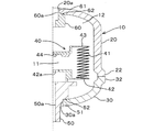
図1は本発明の一実施形態に係るアキュムレータの縦断面を示しており、図中符合10は円筒状のシェル、40はシェル10の内部を油室11とガス室12とに区画する金属製ベローズ(緩衝材)、50は油室11側の連通路を形成するポート、60はガス室12を封止するプラグが装着されるプラグリテーナ(栓部材)である。
【0010】
シェル10は、主体をなすボトムシェル(シェル分割体)20と、ボトムシェル20よりも軸方向長さが短いキャップシェル(シェル分割体)30とが接合されて密封容器を構成しており、各シェル20,30は、接合前は軸方向に分割されたものである。各シェル20,30は、鋼等の金属によってほぼ均一の肉厚にプレス成形されたものであり、軸方向に延びる胴部どうしが溶接により接合されている。
【0011】
ベローズ40は、軸方向に伸縮するベローズ本体41と、ベローズ本体41の一端に固着されたボトムシール42と、ベローズ本体41の他端に固着されたベローズキャップ43とから構成されている。ベローズ本体41に対するボトムシール42とベローズキャップ43の固着手段は、TIGまたはプラズマ等の溶接手段による。ベローズ40は、ボトムシール42がポート50に溶接によって固着され、その内部空間が油室11を構成しており、ベローズ40とシェル10との間に画成される空間がガス室12を構成している。油室11は図示せぬ油圧回路に連通され、また、ガス室12には所定圧力で窒素ガス等の不活性ガスが封入される。ボトムシール42の中心には油口42aが形成されており、また、ベローズキャップ43の内面には、ベローズ本体41の過剰な圧縮と、それに伴うベローズキャップ43自身の損傷を防ぐゴム製のセルフシール44が貼着されている。
【0012】
ポート50は、キャップシェル30の中心に形成された透孔30aに嵌合する嵌合周部51と、嵌合周部51から外径側に延びてキャップシェル30の内面に係合する環状段部52とを備えた円筒体であり、その中心には、油圧回路に連通する油通路50aが形成されている。ポート50は、キャップシェル30の内側から透孔30aに挿入され、段部52をキャップシェル30の内面に係合させて嵌合周部51を透孔30aに嵌合させてキャップシェル30に対し溶接によって固着されている。
【0013】
プラグリテーナ60は、ボトムシェル20の中心に形成された透孔20aに嵌合する嵌合周部61と、嵌合周部61から外径側に延びてボトムシェル20の内面に係合する環状段部62とを備えた円筒体であり、ボトムシェル20に対し溶接によって固着されている。プラグリテーナ60の中心にはガス導入口60aが形成されており、このガス導入口60aは、ガス室12内にガスを封入した後、図示せぬプラグがねじ止めされることにより封止される。
【0014】
以上の構成からなる本実施形態のアキュムレータによれば、ポート50の油通路50aからボトムシール42の油口42aを経て油室11内に導入された圧油の圧力が、ガス室12のガス圧を超えると、ベローズ本体41が伸張してガス室12内のガスが収縮し、一方、油室11内の圧油の圧力がガス室12内のガス圧を下回るとベローズ本体41が収縮してガス室12内のガス圧が膨張する。このようなガス室12内のガスの膨縮作用により油圧回路の圧油の圧力変動が緩衝され、圧油の脈動が抑制される。
【0015】
次いで、本発明に係る上記アキュムレータの製造方法を、工程順に説明する。
[第1の工程]キャップシェルに対するベローズおよびポートの取り付け
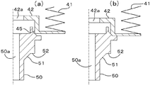
まず、図1に示すように、ベローズ40を構成するボトムシール42に、TIG溶接またはプラズマ溶接等によってベローズ本体41を溶接する。次いで、ボトムシール42をポート50に溶接する。図2(a)に示すように、ボトムシール42の下側の屈曲部の内面には、溶接前には断面ほぼ直角のエッジ45が形成されており、このエッジ45をポート50の溶接部に突き当て、かつポート50側に加圧した状態で、図2(b)に示すように両者を抵抗溶接する。エッジ45は突起であることから、この溶接はプロジェクション溶接であり、溶接に際しては主にボトムシール42のエッジ45が溶融して溶接される。
【0016】
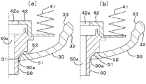
次いで、キャップシェル30とポート50とを同様にプロジェクション溶接する。図3(a)に示すように、溶接前においては、ポート50をキャップシェル30の透孔30aに内側から挿入した状態では、透孔30aの奥側(図3で上側)のエッジ31がポート50の嵌合周部51に突き当たる状態となっている。この状態から、エッジ31を奥側に加圧しながら、図3(b)に示すように両者を抵抗溶接する。溶接に際しては、主にキャップシェル30のエッジ31が溶融して溶接される。次に、図1に示すように、ベローズ40を構成するベローズキャップ43を、TIG溶接またはプラズマ溶接等によってベローズ本体41に溶接する。
【0017】
[第2の工程]ボトムシェルに対するプラグリテーナの取り付け
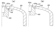
次いで、ボトムシェル20にプラグリテーナ60をプロジェクション溶接する。図4(a)に示すように、溶接前においては、プラグリテーナ60をボトムシェル20の透孔20aに内側から挿入した状態では、透孔20aの奥側(図4で下側)のエッジ21がプラグリテーナ60の嵌合周部61に突き当たる状態となっている。この状態から、エッジ21を奥側に加圧しながら、図4(b)に示すように両者を抵抗溶接する。溶接に際しては、主にボトムシェル20のエッジ21が溶融して溶接される。
【0018】
以上の第1,第2の工程により、キャップシェル30にはベローズ40およびポート50が取り付けられ、ボトムシェル20にはプラグリテーナ60が取り付けられた。次に、ボトムシェル20とキャップシェル30とをプロジェクション溶接によって接合する。
【0019】
[第3の工程]ボトムシェルとキャップシェルとの接合
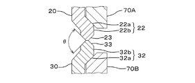
図5に示すように、各シェル20,30の互いの接合部には、外周側に突出する環状周縁部22,32が全周にわたってそれぞれ形成されている。これら環状周縁部22,32は、軸方向に対して約45゜の角度で突出する円錐部22a,32aと、この円錐部22a,32aの先端から接合側に向かって軸方向に延びる短い周部22b,32bとから構成されている。そして、各シェル20,30においては、周部22b,32bの先端に、接合側に向かって先細りとなる三角形状の環状突起部23,33が全周にわたってそれぞれ形成されている。
【0020】
各シェル20,30を接合するには、図5に示すように、両者の環状突起部23,33を突き合わせ、環状周縁部22,32を一対の環状の電極70A,70Bで挟み込み、さらにこれら電極70A,70Bによって加圧することにより環状突起部23,33どうしを強く突き合わせ、この状態を保持して電極70A,70Bに通電しプロジェクション溶接する。溶接に際しては、各環状突起部23,33が溶融して溶接される。なお、環状突起部23,33を突き合わせた状態での開先角度(図5の角度θ)は、約90゜となる。
【0021】
上記実施形態は、ポート50およびプラグリテーナ60をプロジェクション溶接によって各シェル20,30に固着し、この後、シェル20,30どうしをプロジェクション溶接によって接合するものである。プロジェクション溶接は、ほぼ一瞬で溶接が完了するため、きわめて短時間でアキュムレータを製造することができ、その結果、量産性が向上するとともにコストの低減が図られる。
【0022】
ところで、プロジェクション溶接は、溶接する母材の熱容量に大きな差異があると良好に行うことができないものであるが、本実施形態の場合はボトムシェル20とキャップシェル30の肉厚がほぼ均一であることから熱容量もほぼ等しい。したがって、プロジェクション溶接が良好に行われ、シェル10の密封状態が確実かつ強固なものとなる。また、ボトムシェル20とキャップシェル30の肉厚をほぼ均一にするには、切削や鍛造といった加工を要さずプレス成形によって好適になされ、この成形方法によって、製造コストの低減が助長される。
【0023】
また、ポート50は透孔30aにキャップシェル30の内側から嵌合され、環状段部52がキャップシェル30の内面に係合している。また、プラグリテーナ60は透孔60aにボトムシェル20の内側から嵌合され、環状段部62がボトムシェル20の内面に係合している。これにより、ポート50およびプラグリテーナ60は嵌合状態でシェル10の外部側への自身の移動が規制され、シェル10からの抜け止めが確実になされている。このため、シェル10の内圧の上昇によるポート50およびプラグリテーナ60の万一の抜けが防止される。
【0024】
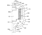
上記アキュムレータは、ベローズ40の内部が油室11を構成する形式であったが、本発明の製造方法は、図6に示すベローズ40の内部がガス室12を構成する形式のアキュムレータにも適用することができる。同図においては、図1と同一の構成要素には同一の符合を付してある。この場合、プラグリテーナ60にベローズ40のボトムシール42が溶接され、ボトムシール42にはガス導入口42bが形成されている。また、ベローズキャップ43の外面にセルフシール44が貼着されている。そして、ベローズ40の内部空間がガス室12を構成しており、ベローズ40とシェル10との間に画成される空間が油室11を構成している。組立の手順は、ボトムシール42をポート50に溶接する代わりにプラグリテーナ60に溶接する以外は上記実施形態と同様であり、溶接方法も同様に行って当該アキュムレータを製造することができる。
【0025】
なお、上記実施形態のアキュムレータにおいては、シェル10の内部を油室11とガス室12とに区画する緩衝材として金属製ベローズ40を用いているが、ベローズ40は金属以外の材料からなるものであってもよい。また、緩衝材としてはベローズに限られるものではなく、ピストン、ダイヤフラム、風船等を用いることもできる。また、圧油の経路はポート50の油通路50aを出入りする形式であったが、油室11への圧油の入口と出口とをそれぞれ別個に有し、圧油の経路が軸方向に沿ったインライン式のアキュムレータにも本発明を適用することができる。
【0026】
【発明の効果】
以上説明したように本発明によれば、ポートおよび栓部材を抵抗溶接によって各シェル分割体に固着し、この後、シェル分割体どうしを抵抗溶接によって接合するので、製造時間が大幅に短縮され、その結果、量産性が向上するとともにコストの低減が図られるといった効果を奏する。
【図面の簡単な説明】
【図1】 本発明の一実施形態に係るアキュムレータの縦断面図である。
【図2】 ベローズのボトムシールとポートとをプロジェクション溶接する工程を示す縦断面図であって、(a)は溶接前、(b)は溶接後である。
【図3】 キャップシェルとポートとをプロジェクション溶接する工程を示す縦断面図であって、(a)は溶接前、(b)は溶接後である。
【図4】 キャップシェルとプラグリテーナとをプロジェクション溶接する工程を示す縦断面図であって、(a)は溶接前、(b)は溶接後である。
【図5】 ボトムシェルとキャップシェルとをプロジェクション溶接する前の状態を示す接合部の縦断面図である。
【図6】 本発明に係るアキュムレータの変形例を示す縦断面図である。
【符号の説明】
10…シェル、11…油室、12…ガス室、20…ボトムシェル(シェル分割体)、30…キャップシェル(シェル分割体)、40…ベローズ(緩衝材)、50…ポート、50a…連通路、52,62…環状段部、60…プラグリテーナ(栓部材)、60a…ガス導入口。[0001]
BACKGROUND OF THE INVENTION
The present invention relates to a method for manufacturing an accumulator used in a hydraulic circuit or the like of a hydraulic control device, and more particularly to a technique for improving the efficiency of manufacturing processes and reducing costs.
[0002]
[Prior art]
The accumulator is generally divided into a gas chamber and an oil chamber by a bellows inside a cylindrical shell, and the pressure fluctuation of oil flowing into the oil chamber is buffered by the expansion and contraction of the gas in the gas chamber accompanying the expansion and contraction of the bellows. As a component that effectively suppresses pulsation generated in oil flowing in a hydraulic circuit, it is widely applied to, for example, a hydraulic circuit of an automobile. The accumulator has a configuration in which a cap is screwed into the opening of the bottomed cylindrical shell body. In this case, the cap is formed by using a processing means such as forging or cutting, and both Since it is necessary to form a screw, the cost was increased. Therefore, an accumulator is provided in which two shell divided bodies molded by press molding are joined together by welding.
[0003]
[Problems to be solved by the invention]
Conventionally, welding methods such as gas welding and TIG welding have been employed to weld the shell divided bodies together. In addition, there are cases where accessory parts such as a port formed with a communication path to the hydraulic circuit and a plug retainer to which a plug for sealing the gas chamber is attached are fixed inside the shell. The same welding method was used. However, such a welding method is time consuming and inferior in mass productivity, leading to an increase in cost. For this reason, there is a problem that the cost reduction effect by forming the shell divided body by press molding is diminished. It was.
Therefore, an object of the present invention is to provide a method for manufacturing an accumulator capable of reducing manufacturing time and cost based on an efficient manufacturing procedure and a suitable welding method.
[0004]
[Means for Solving the Problems]
According to a first aspect of the present invention, a shell formed by joining two shell divided bodies that are divided in the axial direction is divided into an oil chamber that communicates the inside with a hydraulic circuit and a gas chamber that contains gas. A method of manufacturing an accumulator incorporating a partitioning cushioning material, the port being formed with a communication path to the hydraulic circuit, communicating with the communication path, the inside as an oil chamber, and the outside as a gas chamber. A first member for attaching the partitioning cushioning material and fixing the port to one shell divided body by resistance welding, and a plug member in which the other shell divided body is formed with a gas introduction port communicating with the gas chamber A second step of fixing the shell parts by resistance welding, and a third step of joining the shell divided bodies to each other by resistance welding to form a shell containing the cushioning material therein , and joining the shell divided parts to each other On the outer peripheral side The projecting annular peripheral edge is formed over the entire circumference of the shell divided body, and the outer peripheral parts of each annular peripheral edge have a conical part formed with an inclined surface approaching toward the outside, in the third step, The resistance welding of the shell divided body is characterized in that it is performed by pressing the inclined surfaces of the conical portions of the annular peripheral portions with the electrodes and butting the joint portions with each other .
[0005]
The accumulator according to the first aspect of the present invention is a type in which the interior of the cushioning material constitutes an oil chamber, and the space between the cushioning material and the shell constitutes a gas chamber. According to the present invention, the port and the plug member are fixed to each shell divided body by resistance welding, and then the shell divided bodies are joined by resistance welding. In resistance welding, since the welding is completed almost instantly when electricity is applied to the electrodes brought into contact with the two members to be welded, the working time is greatly shortened, so that the mass productivity is improved and the cost is reduced.
[0006]
According to a second aspect of the present invention, in a shell formed by joining two shell divided bodies that are divided in the axial direction, an oil chamber that communicates the inside with a hydraulic circuit and a gas chamber in which a gas is sealed. A method of manufacturing an accumulator incorporating a partitioning cushioning material, the first step of fixing a port formed with a communication path to the hydraulic circuit to one shell divided body by resistance welding, and a gas chamber A buffer member that is connected to the gas inlet and is connected to the gas inlet and is provided with a buffer material that divides the inside into a gas chamber and the outside into an oil chamber. A second step of fixing to the divided body by resistance welding and a third step of joining the shell divided bodies to each other by resistance welding to form a shell containing the cushioning material therein are provided.
[0007]
The accumulator according to the second invention is a type in which the interior of the cushioning material constitutes a gas chamber, and the space between the cushioning material and the shell constitutes an oil chamber, and the effect produced is the first invention. It is the same.
The first step and the second step in each of the above inventions may be performed in this order, or the order may be reversed. Moreover, you may perform both in parallel. As a type of resistance welding, so-called projection welding in which protrusions are formed on at least one of the joints is preferable from the viewpoint of ensuring sufficient joint strength.
[0008]
In each of the above inventions, the port and the plug member are fitted from the inner side of the shell divided body, and the port and the plug member are engaged with the inner surface of the shell divided body in the fitted state. It is preferable that a step portion for restricting its own movement toward the outside is formed. According to this aspect, the stepped portion engages with the inner surface of the shell divided body, so that the port and the plug member are reliably prevented from coming off from the shell. Omission is prevented.
[0009]
DETAILED DESCRIPTION OF THE INVENTION
Next, an embodiment of the present invention will be described with reference to the drawings.
FIG. 1 shows a longitudinal section of an accumulator according to an embodiment of the present invention. In the figure,
[0010]
The
[0011]
The
[0012]
The
[0013]
The
[0014]
According to the accumulator of the present embodiment having the above configuration, the pressure of the pressure oil introduced into the
[0015]
Next, a method for manufacturing the accumulator according to the present invention will be described in the order of steps.
[First Step] Attachment of Bellows and Port to Cap Shell First, as shown in FIG. 1, a
[0016]
Next, the
[0017]
[Second Step] Attaching the Plug Retainer to the Bottom Shell Next, the
[0018]
Through the first and second steps described above, the
[0019]
[Third Step] Joining of Bottom Shell and Cap Shell As shown in FIG. 5, annular
[0020]
In order to join the
[0021]
In the above embodiment, the
[0022]
By the way, projection welding cannot be performed satisfactorily when there is a large difference in the heat capacities of the base metals to be welded. In the present embodiment, the thickness of the
[0023]
The
[0024]
The accumulator has a form in which the inside of the
[0025]
In the accumulator of the above embodiment, the metal bellows 40 is used as a buffer material that partitions the inside of the
[0026]
【The invention's effect】
As described above, according to the present invention, the port and the plug member are fixed to each shell divided body by resistance welding, and then the shell divided bodies are joined by resistance welding, so that the manufacturing time is greatly shortened, As a result, there is an effect that the mass productivity is improved and the cost is reduced.
[Brief description of the drawings]
FIG. 1 is a longitudinal sectional view of an accumulator according to an embodiment of the present invention.
FIGS. 2A and 2B are longitudinal sectional views showing a process of projection welding a bottom seal and a port of a bellows, wherein FIG. 2A is before welding, and FIG. 2B is after welding.
FIGS. 3A and 3B are longitudinal sectional views showing a process of projection welding a cap shell and a port, wherein FIG. 3A is before welding and FIG. 3B is after welding.
FIGS. 4A and 4B are longitudinal sectional views showing a process of projection welding the cap shell and the plug retainer, wherein FIG. 4A is before welding, and FIG. 4B is after welding.
FIG. 5 is a longitudinal sectional view of a joint portion showing a state before projection welding of a bottom shell and a cap shell.
FIG. 6 is a longitudinal sectional view showing a modification of the accumulator according to the present invention.
[Explanation of symbols]
DESCRIPTION OF
Claims (3)
前記油圧回路への連通路が形成されたポートに、連通路に連通してその内部を前記油室に、また外部を前記ガス室に区画する前記緩衝材を取り付けるとともに、このポートを、一方のシェル分割体に抵抗溶接によって固着する第1の工程と、
他方のシェル分割体に、前記ガス室に連通するガス導入口が形成された栓部材を抵抗溶接によって固着する第2の工程と、
前記各シェル分割体を抵抗溶接により互いに接合して前記緩衝材を内部に収納したシェルを構成する第3の工程と
を備え、
前記シェル分割体の互いの接合部には、その外周側に突出する環状周縁部が前記シェル分割体の全周にわたって形成され、互いの前記環状周縁部の外周部は、外側に向かうに従って接近する傾斜面が形成された円錐部を有し、
前記第3の工程において、前記シェル分割体の抵抗溶接は、互いの前記環状周縁部の円錐部の傾斜面を電極により加圧して互いの前記接合部を突き合わせることにより行うことを特徴とするアキュムレータの製造方法。An accumulator in which a shock absorbing material that divides the inside into an oil chamber communicating with a hydraulic circuit and a gas chamber filled with gas is incorporated in a shell formed by joining two shell divided bodies divided in the axial direction. A method of manufacturing comprising:
The port having a communication path to the hydraulic circuit is attached with the cushioning material that communicates with the communication path and divides the inside into the oil chamber and the outside into the gas chamber. A first step of fixing to the shell divided body by resistance welding;
A second step of fixing, by resistance welding, a plug member in which a gas introduction port communicating with the gas chamber is formed on the other shell divided body;
A third step of forming shells in which the respective shell divided bodies are joined together by resistance welding and the cushioning material is housed therein ;
At the joint portions of the shell divided bodies, an annular peripheral edge projecting to the outer peripheral side is formed over the entire periphery of the shell divided bodies, and the outer peripheral portions of the annular peripheral edges approach each other toward the outside. Having a conical portion formed with an inclined surface;
In the third step, the resistance welding of the shell divided bodies is performed by pressing the inclined surfaces of the conical portions of the annular peripheral edge portions with electrodes and abutting the joint portions with each other. Manufacturing method of accumulator.
一方のシェル分割体に、前記油圧回路への連通路が形成されたポートを抵抗溶接によって固着する第1の工程と、
前記ガス室に連通するガス導入口が形成された栓部材に、ガス導入口に連通してその内部を前記ガス室に、また外部を前記油室に区画する前記緩衝材を取り付けるとともに、この栓部材を、他方のシェル分割体に抵抗溶接によって固着する第2の工程と、
前記各シェル分割体を抵抗溶接により互いに接合して前記緩衝材を内部に収納したシェルを構成する第3の工程と
を備えることを特徴とするアキュムレータの製造方法。An accumulator in which a shock absorbing material that divides the inside into an oil chamber communicating with a hydraulic circuit and a gas chamber filled with gas is incorporated in a shell formed by joining two shell divided bodies divided in the axial direction. A method of manufacturing comprising:
A first step of fixing a port formed with a communication path to the hydraulic circuit to one shell divided body by resistance welding;
The stopper member formed with a gas inlet port communicating with the gas chamber is attached with the buffer material communicating with the gas inlet port, the interior of which is partitioned into the gas chamber, and the exterior thereof being partitioned into the oil chamber. A second step of fixing the member to the other shell divided body by resistance welding;
And a third step of forming a shell in which the buffer members are housed by joining the shell divided bodies to each other by resistance welding.
Priority Applications (1)
| Application Number | Priority Date | Filing Date | Title |
|---|---|---|---|
| JP29379399A JP4265712B2 (en) | 1999-10-15 | 1999-10-15 | Manufacturing method of accumulator |
Applications Claiming Priority (1)
| Application Number | Priority Date | Filing Date | Title |
|---|---|---|---|
| JP29379399A JP4265712B2 (en) | 1999-10-15 | 1999-10-15 | Manufacturing method of accumulator |
Publications (2)
| Publication Number | Publication Date |
|---|---|
| JP2001116002A JP2001116002A (en) | 2001-04-27 |
| JP4265712B2 true JP4265712B2 (en) | 2009-05-20 |
Family
ID=17799244
Family Applications (1)
| Application Number | Title | Priority Date | Filing Date |
|---|---|---|---|
| JP29379399A Expired - Lifetime JP4265712B2 (en) | 1999-10-15 | 1999-10-15 | Manufacturing method of accumulator |
Country Status (1)
| Country | Link |
|---|---|
| JP (1) | JP4265712B2 (en) |
Families Citing this family (3)
| Publication number | Priority date | Publication date | Assignee | Title |
|---|---|---|---|---|
| WO2003064862A1 (en) * | 2002-01-31 | 2003-08-07 | Nhk Spring Co., Ltd. | Accumulator |
| JP4272604B2 (en) | 2004-08-23 | 2009-06-03 | 日本発條株式会社 | Pressure vessel and pressure accumulator / buffer |
| DE102004043352A1 (en) * | 2004-09-08 | 2006-03-23 | Hydac Technology Gmbh | hydraulic accumulator |
-
1999
- 1999-10-15 JP JP29379399A patent/JP4265712B2/en not_active Expired - Lifetime
Also Published As
| Publication number | Publication date |
|---|---|
| JP2001116002A (en) | 2001-04-27 |
Similar Documents
| Publication | Publication Date | Title |
|---|---|---|
| EP1052412B1 (en) | Accumulator and manufacturing process thereof | |
| US7022932B2 (en) | Outer shell unit and method of manufacturing the unit | |
| US7325571B2 (en) | Pressure container and pressure accumulating/buffer apparatus | |
| US8282305B2 (en) | Ball sleeve joint and process for manufacturing same | |
| JP5695032B2 (en) | Fluid pressure accumulator | |
| US20100140920A1 (en) | Pipe joint including a pipe and method for producing a joint section of a pipe joint | |
| US20070102052A1 (en) | Accumulator | |
| KR20130064718A (en) | Cylinder device | |
| US20040119212A1 (en) | Air spring cover and method of making the same | |
| KR101524068B1 (en) | Car link and production method | |
| JP4265712B2 (en) | Manufacturing method of accumulator | |
| JP4225396B2 (en) | Manufacturing method of accumulator | |
| JP4480232B2 (en) | accumulator | |
| JP2002039102A (en) | accumulator | |
| KR20160137735A (en) | Apparatus and method for manufacturing car links | |
| US20210187656A1 (en) | Method for manufacturing a hydraulic housing, hydraulic housing | |
| US20190293143A1 (en) | Cylinder Unit having a Scaled Bottom | |
| JP3818353B2 (en) | accumulator | |
| JP6546871B2 (en) | Method of manufacturing cylinder | |
| JPWO2003064862A1 (en) | accumulator | |
| JPS598078Y2 (en) | Pressure-resistant small container | |
| JP3581615B2 (en) | Liquid filled type vibration damping device | |
| JPH0521669B2 (en) | ||
| JP2724096B2 (en) | Anti-vibration member and method of manufacturing the same | |
| JP4093358B2 (en) | Suspension support manufacturing method |
Legal Events
| Date | Code | Title | Description |
|---|---|---|---|
| A621 | Written request for application examination |
Free format text: JAPANESE INTERMEDIATE CODE: A621 Effective date: 20060515 |
|
| A977 | Report on retrieval |
Free format text: JAPANESE INTERMEDIATE CODE: A971007 Effective date: 20081114 |
|
| A131 | Notification of reasons for refusal |
Free format text: JAPANESE INTERMEDIATE CODE: A131 Effective date: 20081118 |
|
| A521 | Written amendment |
Free format text: JAPANESE INTERMEDIATE CODE: A523 Effective date: 20090115 |
|
| TRDD | Decision of grant or rejection written | ||
| A01 | Written decision to grant a patent or to grant a registration (utility model) |
Free format text: JAPANESE INTERMEDIATE CODE: A01 Effective date: 20090210 |
|
| A01 | Written decision to grant a patent or to grant a registration (utility model) |
Free format text: JAPANESE INTERMEDIATE CODE: A01 |
|
| A61 | First payment of annual fees (during grant procedure) |
Free format text: JAPANESE INTERMEDIATE CODE: A61 Effective date: 20090210 |
|
| R150 | Certificate of patent or registration of utility model |
Ref document number: 4265712 Country of ref document: JP Free format text: JAPANESE INTERMEDIATE CODE: R150 Free format text: JAPANESE INTERMEDIATE CODE: R150 |
|
| FPAY | Renewal fee payment (event date is renewal date of database) |
Free format text: PAYMENT UNTIL: 20120227 Year of fee payment: 3 |
|
| FPAY | Renewal fee payment (event date is renewal date of database) |
Free format text: PAYMENT UNTIL: 20120227 Year of fee payment: 3 |
|
| FPAY | Renewal fee payment (event date is renewal date of database) |
Free format text: PAYMENT UNTIL: 20130227 Year of fee payment: 4 |
|
| R250 | Receipt of annual fees |
Free format text: JAPANESE INTERMEDIATE CODE: R250 |
|
| FPAY | Renewal fee payment (event date is renewal date of database) |
Free format text: PAYMENT UNTIL: 20140227 Year of fee payment: 5 |
|
| R250 | Receipt of annual fees |
Free format text: JAPANESE INTERMEDIATE CODE: R250 |
|
| R250 | Receipt of annual fees |
Free format text: JAPANESE INTERMEDIATE CODE: R250 |
|
| R250 | Receipt of annual fees |
Free format text: JAPANESE INTERMEDIATE CODE: R250 |
|
| R250 | Receipt of annual fees |
Free format text: JAPANESE INTERMEDIATE CODE: R250 |
|
| R250 | Receipt of annual fees |
Free format text: JAPANESE INTERMEDIATE CODE: R250 |
|
| R250 | Receipt of annual fees |
Free format text: JAPANESE INTERMEDIATE CODE: R250 |
|
| R250 | Receipt of annual fees |
Free format text: JAPANESE INTERMEDIATE CODE: R250 |
|
| EXPY | Cancellation because of completion of term |