EP1354742A1 - Kraftfahrzeug mit einem öffnungsfähigen Verdeck - Google Patents
Kraftfahrzeug mit einem öffnungsfähigen Verdeck Download PDFInfo
- Publication number
- EP1354742A1 EP1354742A1 EP03005997A EP03005997A EP1354742A1 EP 1354742 A1 EP1354742 A1 EP 1354742A1 EP 03005997 A EP03005997 A EP 03005997A EP 03005997 A EP03005997 A EP 03005997A EP 1354742 A1 EP1354742 A1 EP 1354742A1
- Authority
- EP
- European Patent Office
- Prior art keywords
- motor vehicle
- leg
- vehicle according
- connecting device
- bracket
- Prior art date
- Legal status (The legal status is an assumption and is not a legal conclusion. Google has not performed a legal analysis and makes no representation as to the accuracy of the status listed.)
- Granted
Links
Images


Classifications
-
- B—PERFORMING OPERATIONS; TRANSPORTING
- B60—VEHICLES IN GENERAL
- B60J—WINDOWS, WINDSCREENS, NON-FIXED ROOFS, DOORS, OR SIMILAR DEVICES FOR VEHICLES; REMOVABLE EXTERNAL PROTECTIVE COVERINGS SPECIALLY ADAPTED FOR VEHICLES
- B60J7/00—Non-fixed roofs; Roofs with movable panels, e.g. rotary sunroofs
- B60J7/08—Non-fixed roofs; Roofs with movable panels, e.g. rotary sunroofs of non-sliding type, i.e. movable or removable roofs or panels, e.g. let-down tops or roofs capable of being easily detached or of assuming a collapsed or inoperative position
- B60J7/12—Non-fixed roofs; Roofs with movable panels, e.g. rotary sunroofs of non-sliding type, i.e. movable or removable roofs or panels, e.g. let-down tops or roofs capable of being easily detached or of assuming a collapsed or inoperative position foldable; Tensioning mechanisms therefor, e.g. struts
- B60J7/1226—Soft tops for convertible vehicles
- B60J7/1234—Soft tops for convertible vehicles characterised by arches, e.g. shape or material
- B60J7/1247—Tensioning bow at rear of soft top
Definitions
- the invention is based on a motor vehicle, in particular Passenger car, with a hood, according to the preamble of claim 1.
- a generic motor vehicle is known from DE 44 41 666 C1. It includes a convertible top which spans the passenger compartment of the motor vehicle Closed position can be converted into a rear storage position.
- the hood has a Convertible top linkage that, in addition to other linkage parts, has a U - shaped clamping bracket has in the closed position of the top in an approximately horizontal clamping position or can be moved into an upward, for example upright, assembly position.
- a convertible top cover is assigned to the convertible top, which is attached to the convertible top linkage is held in position and has a rigid rear window.
- the mounting position can are also referred to as a service position and serve in particular for accessibility to a receiving space under the clamp or for maintenance and / or Repair work on the convertible top.
- the clamping bracket which can be brought into the assembly position, has proven itself in the mid-motor arrangement to maintain accessibility to the drive motor, even if the rest Convertible top parts to the closed position.
- the Detachable connecting device of the clamping bracket decoupled from the swivel axis can be so that it is in the desired mounting position upwards, d. H. from his horizontal clamping position can be pivoted against the direction of travel without that the rear window interferes with the swivel path.
- the Accessibility to the rear-side receiving space can be created if the Tensioning bracket is transferred to the mounting position.
- the mounting position of the clamping bracket are also internal convertible top parts, for example for adjustment work accessible so that the clamp according to the invention not only with motor vehicles Mid-motor arrangement can be used.
- each leg is U-shaped Clamping bracket made in two parts. Both leg parts of each leg are therefore over the connecting device is attached to each other and can via the Connection device can also be released from each other so that the clamping bracket in the Mounting position is transferable.
- a connecting device is preferred in which the two parts of the leg are not can be completely separated from each other, but a relative movement of these two Leg parts are given to each other.
- this can be done in a simple and favorable way by a folding axis provided in addition to the pivot axis can be achieved, which runs at a distance and approximately parallel to the pivot axis.
- the clamping bracket is brought into the assembly position.
- the folding axis is preferably arranged above the pivot axis.
- connection device can be used as separable or extendable plug-in coupling to be formed on one of the Leg parts of one leg a plug element receptacle and on the other Leg part of the same leg has a plug-in element, which when closed Connection device is present in the plug element receptacle.
- the clamping bracket With separate Plug-in coupling, the clamping bracket is extended so that it is rigid Rear window is movable around the pivot axis in monthly position.
- the clamping bracket in Installation position be shifted in that each leg end in the direction of Has aligned longitudinal axis of the leg elongated hole into which the Swiveling axis engages. Therefore, in this variant, too Extension of the legs reached.
- the clamping bracket with the Connection device in a first predetermined with respect to the pivot axis Fix or lock sliding position, this first sliding position of the Clamping position of the clamping bracket is assigned.
- the connection device is released the tensioning bracket moved along the elongated hole into the second sliding position, which is the Mounting position of the clamp is assigned.
- the motor vehicle 3 is preferably a convertible with the convertible top 2.
- the vehicle body also has below the belt line 1 one side door 4a per side of the vehicle with side window 4b and in addition to one here not shown front area a rear area 5.
- the structure is a in assigned to a windshield frame 6 arranged windshield 7.
- the Convertible top 2 spans passenger compartment 8 in the closed position St shown in FIG. 1 of the motor vehicle 3.
- the convertible top 2 can be in a position not shown here Storage position are transferred, in the rear area 5 in a below one rear convertible top compartment lid 9 is stored.
- the motor vehicle 3 is a two-seater sports car, in which the engine is in a mid-engine configuration a receiving space 10 can be arranged, in particular below the Convertible top storage compartment and is arranged behind the passenger compartment 8.
- the convertible top 2 comprises a convertible top linkage 18 (FIG. 2), of which a side roof frame 11 can be seen in FIG. 1.
- the convertible top linkage 18 furthermore has at least one transversely extending one, indicated here by dashed lines Bow 12 and / or 13, the front bow 12 in particular the Main bow and the rear bow 13 can form the corner bow.
- At the Convertible top linkage 18 is also held in a convertible top cover 14, in one Rigid rear window 15 used and preferably only with the Convertible top cover 14 is connected.
- the top 2 extends in the closed position St from Rear area 5 to the cross frame part 16 of the windshield frame 6.
- the front convertible top section lying adjacent to the frame cross part 16 17 is designed as a dimensionally stable shell covered by the top cover 14.
- the Convertible top linkage 18 is on a convertible top storage connected to the vehicle body 19 movable deflected to move it from the closed position St to the rear To be able to shift storage position.
- the top linkage 18 has here next to the side roof frame 11 still a pair of side links 20a, 20b, the one Quadrilateral can form. Both links 20a, 20b are at one end Roof frame 11, in particular in the area of section 17, and with their other End on the top storage 19 or other parts of the top linkage 18 pivoted hinged.
- the main bow 12 is pivotally attached to the top storage 19. The in Fig.
- the convertible top linkage 18 is assigned a rear clamping bracket 21, which on Convertible top linkage 18 or on the convertible top bearing 19 about a pivot axis 22 is mounted so that it has the approximately horizontal clamping position Sp can take in which he holds the convertible top cover 14 on the convertible top linkage 18.
- Its pivot axis 22 is in particular on the main bow 12 in its lower one Area, for example adjacent to its articulation axis 23 on the convertible top bearing 19, intended.
- the clamping bracket 21 is - as indicated in particular in Fig. 1 - U-shaped executed curved and symmetrical to the vehicle central longitudinal plane.
- the clamping bracket 21 has two clamping bracket legs, of which only one Leg 24 is visible and it has a leg 24 connecting Clamping bracket base 25.
- the clamping bracket 21 is around the respective free leg end 26 the pivot axis 22 pivotally held so that it from the clamping position Sp Direction of arrow 27 upwards in a service or assembly position, that is to say in the opposite direction the direction of travel Fr is foldable. So that when transferring the clamp 21 from the Clamping position Sp in the mounting position does not prevent the rear window 15 is one of the Clamping bracket 21 decoupling from its fixed position assignment to the pivot axis 22
- Connecting device 28 is provided, with which each leg 24 of the U - shaped clamp 21 releasable and reconnectable to the pivot axis 22 connected is.
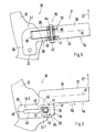
- the connecting device 28 is available in different Exemplary embodiments are described in more detail below with reference to FIGS. 3 to 6.
- leg 24 of the U-shaped clamping bracket 21 is made in two parts and thus comprises two leg parts 29 and 30, which over the Connection device 28 are connected to each other.
- the connecting device 28 is provided near the pivot axis 22, so that the one with the pivot axis 22 connected leg part 29 is significantly shorter than the other leg part 30 is.
- the connecting device 28 is shown in FIG. 3 equipped with a folding axis 31 which is parallel to the pivot axis 22, but with Distance Ah and / or Al runs to which distance in the direction of Vehicle longitudinal axis Fl (distance Al) and / or in the direction of the vehicle vertical axis Fh (Distance Ah) is measured.
- the folding axis 31 is above the Swivel axis 22 and preferably above the central longitudinal axis 32 of the leg 24 is arranged, while the pivot axis 22 below this central longitudinal axis 32 can lie.
- each leg part 29 or 30 has one Lock stop 33 and 34, which face each other and thus only one Allow folding direction in arrow direction 27 and the other folding direction opposite arrow Lock 27 when the clamping bracket 21 is in the clamping position Sp. So that the clamp 21 is not inadvertently shifted into the mounting position, is the connecting device assigned a removable locking element 35, which as anchoring means with a tension rope Sn is realized and the tensioning bracket 21 downwards, that is to say in the opposite direction Direction of arrow 27 is applied.
- the tensioning rope Sn is between the tensioning bracket 21 and for example, the structure of the motor vehicle is releasably clamped and pulls both Lock stops 33 and 34 against each other.
- connection device 28 shown in FIG. 4 after a second Embodiment is the removable locking member 35 of one movable latch 36 is formed, which engages in both leg parts 29 and 30 when the Connection device 28 is closed.
- the latch 36 is parallel to, for example
- the central longitudinal axis 32 can be displaced against the force of a spring 37 and thus becomes one of the two leg parts 29 and 30 pulled out and so the folding axis 31 only in Folding direction 27 free.
- the locking stops 33 and 34 can be the same as in the first Embodiment may be provided.
- the end 26 is an L-shaped extension Lf realized.
- the Connection device 28 is here as the leg 24 extending or Leg parts 29 and 30 separating connector 38 performed on one Leg part 29 a plug element receptacle 39 and on the other leg part 30 Has plug element 40.
- Plug element receptacle 39 and plug element 40 are in the Aligned substantially parallel to the central longitudinal axis 32 of the leg 24.
- at closed plug coupling 38 are both the plug element receptacle 39 and the plug-in element 40 is penetrated by the removable locking element 35, the here as a bolt 36 has a screw or plug pin 41, the direction of insertion mainly runs transversely to the central longitudinal axis 32.
- the one with an Ace stop Socket pin 41 can have an external thread at its other end, on the one Securing element 42 can be screwed on, so that the plug pin 41 against slipping out can be secured. If the two leg parts 29 and 30 extended, the clamping bracket 21 about the pivot axis 22 in the mounting position to be spent; however, both leg parts 29 and 30 are completely apart separated, the pivot axis 22 has no function when the mounting position is taken.
- FIG. 6 shows a fourth exemplary embodiment of a connecting device 28 shown.
- the leg 24 of the U-shaped clamping bracket 21 can be made in one piece and it has an elongated hole 43 at the free end 26 through which the pivot axis 22 reaches through.
- an Locking element 35 attached to the level Sf, here as a removable bracket 44 is realized, which surrounds the leg 24 on both sides and possibly the main bow 12.
- the clip 44 engages both on the step Sf of the leg end 26 and on the Swivel axis 22 and has a locking recess 45, which makes it click on the is held, for example, by a pivot axis 22 formed by a bolt.
- a pivot axis 22 formed by a bolt.
- Securing element 46 can be plugged onto the pivot axis.
- a disc 47 Between the Securing element 46 and one of the two clip brackets Kb of clip 44 can also be arranged a disc 47. If the clamping bracket 21 from his 6, the clamping position Sp shown in FIG.
- the clamping bracket 21 can be seen from its first in FIG. 6 Sliding position Sc1 at the first end 48 of the elongated hole 43 in the clamping position Sp in Direction of the vehicle rear area 5 in the elongated hole 43 into a second Sliding position Sc2 are shifted, this second sliding position Sc2 the Is assigned to the mounting position and is located at the second end 49 of the slot 43, the can be aligned parallel to the central longitudinal axis 32.
Landscapes
- Engineering & Computer Science (AREA)
- Mechanical Engineering (AREA)
- Body Structure For Vehicles (AREA)
- Lock And Its Accessories (AREA)
- Window Of Vehicle (AREA)
Abstract
Description
- Fig. 1
- ausschnittweise ein Kraftfahrzeug mit einem Verdeck,
- Fig. 2
- das Verdeck in Detaildarstellung und
- Fig. 3 bis 6
- jeweils ein Ausführungsbeispiel eines Spannbügels.
Claims (14)
- Kraftfahrzeug, insbesondere Personenwagen, mit einem Verdeck, das aus einer den Fahrgastraum des Kraftfahrzeugs überspannenden Schließstellung in eine Ablagestellung überführbar ist und das ein Verdeckgestänge sowie einen am Verdeckgestänge in Lage gehaltenen Verdeckbezug mit einer formsteifen Heckscheibe aufweist, welches Verdeckgestänge wenigstens einen heckseitigen, U - förmigen Spannbügel umfasst, der in Schließstellung des Verdecks in eine etwa horizontale Spannstellung und in eine nach oben geklappte, beispielsweise aufrechte, Montagestellung bewegbar ist und der an seinen freien Bügelenden in einer etwa parallel zur Fahrzeugquerachse verlaufenden Schwenkachse gelagert ist, dadurch gekennzeichnet, dass jeder Schenkel (24) des U - förmigen Spannbügels (21) über eine lösbare Verbindungseinrichtung (28) mit der Schwenkachse (22) verbunden ist.
- Kraftfahrzeug nach Anspruch 1, dadurch gekennzeichnet, dass jeder Schenkel (24) des Spannbügels (21) zweiteilig ausgeführt ist und die beiden Schenkelteile (29, 30) mit der Verbindungseinrichtung (28) lösbar aneinander befestigt sind.
- Kraftfahrzeug nach Anspruch 1 oder 2, dadurch gekennzeichnet, dass die Verbindungseinrichtung (28) eine Klappachse (31) aufweist, die mit Abstand (Ah, Al) und etwa parallel zur Schwenkachse (22) verläuft, und dass der Spannbügel (21) um die Klappachse (31) in die Montagestellung bewegbar ist.
- Kraftfahrzeug nach Anspruch 1 oder 2, dadurch gekennzeichnet, dass die Verbindungseinrichtung (28) als Steckkupplung (38) ausgebildet ist, die an einem Schenkelteil (29, 30) eines Schenkels (24) eine Steckelementaufnahme (39) und an dem anderen Schenkelteil (30, 29) desselben Schenkels (24) ein Steckelement (40) aufweist.
- Kraftfahrzeug nach Anspruch 1, dadurch gekennzeichnet, dass jedes Schenkelende (26) ein in Richtung der Mittellängsachse (32) des Schenkels (24) ausgerichtetes Langloch (43) aufweist, in das die Schwenkachse (22) eingreift, dass der Spannbügel (21) über die Verbindungseinrichtung (28) in einer gegenüber der Schwenkachse (22) vorgegebenen ersten Schiebeposition (Sc1) arretiert ist, welche erste Schiebeposition (Sc1) der Spannstellung (Sp) zugeordnet ist, und dass der Spannbügel (21) bei gelöster Verbindungseinrichtung (28) entlang des Langlochs (43) in eine zweite Schiebeposition (Sc2) verlagerbar ist, welche zweite Schiebeposition (Sc2) der Montagestellung zugeordnet ist und in der die Basis (25) des Spannbügels (21) mit größerem Abstand zur Schwenkachse (22) liegt als in der ersten Schiebeposition (Sc1).
- Kraftfahrzeug nach Anspruch 5, dadurch gekennzeichnet, dass die Verbindungseinrichtung (28) eine abnehmbare Klammer (44) umfasst, die sowohl an dem Schenkelende (26) als auch an der Schwenkachse (22) angreift und den Spannbügel (21) in seiner ersten Schiebeposition (Sc1) relativ zur Schwenkachse (22) hält.
- Kraftfahrzeug nach Anspruch 2, 3 oder 4, dadurch gekennzeichnet, dass die Verbindungseinrichtung (28) ein entfernbares Verriegelungselement (35) besitzt, das die beiden Schenkelteile (29, 30) aneinander hält.
- Kraftfahrzeug nach Anspruch 3, dadurch gekennzeichnet, dass die Klappachse (31) oberhalb der Mittellängsachse (32) der Schenkel (29, 30) des Spannbügels (21) liegt.
- Kraftfahrzeug nach Anspruch 3 oder 8, dadurch gekennzeichnet, dass - ausgehend von in Spannstellung (Sp) vorliegendem Spannbügel (21) - der Spannbügel (21) um die Klappachse (31) lediglich in Richtung (Pfeil 27) in Montagestellung klappbar und die andere, entgegengerichtete Klapprichtung gesperrt ist.
- Kraftfahrzeug nach Anspruch 9, dadurch gekennzeichnet, dass unterhalb der Klappsachse (31) des Schenkels (21) ein Sperranschlag (33, 34) an jedem der Schenkelteile (29, 30) ausgebildet ist und dass in Spannstellung (Sp) des Spannbügels (21) die Sperranschläge (33, 34) aneinander liegen.
- Kraftfahrzeug nach Anspruch 3, 4 oder 7, dadurch gekennzeichnet, dass das Verriegelungselement (35) einen Riegel (36) besitzt, der in beide Schenkelteile (29, 30) eines Schenkels (24) eingreift.
- Kraftfahrzeug nach Anspruch 11, dadurch gekennzeichnet, dass der Riegel entgegen der Kraft einer Feder (37) in einen der Schenkelteile (29, 30) in Freigabestellung verschiebbar ist.
- Kraftfahrzeug nach Anspruch 3, 7, 9 oder 10, dadurch gekennzeichnet, dass das Verriegelungselement (35) durch ein Abspannmittel (Am), insbesondere Seil (Sn) gebildet ist, das sich zwischen dem Spannbügel (21) und dem Kraftfahrzeug (3) erstreckt, und dass das Abspannmittel (Am) die beiden Sperranschläge (33, 34) gegeneinander zieht.
- Kraftfahrzeug nach Anspruch 4 oder 11, dadurch gekennzeichnet, dass das Verriegelungselement (35) als Riegel (36) einen Steckbolzen (41) aufweist, der die Steckelementaufnahme (39) und das Steckelement (40) durchgreift.
Applications Claiming Priority (2)
| Application Number | Priority Date | Filing Date | Title |
|---|---|---|---|
| DE10216893 | 2002-04-17 | ||
| DE10216893A DE10216893C1 (de) | 2002-04-17 | 2002-04-17 | Kraftfahrzeug, insbesondere Personenwagen, mit einem Verdeck |
Publications (2)
| Publication Number | Publication Date |
|---|---|
| EP1354742A1 true EP1354742A1 (de) | 2003-10-22 |
| EP1354742B1 EP1354742B1 (de) | 2008-09-03 |
Family
ID=28458868
Family Applications (1)
| Application Number | Title | Priority Date | Filing Date |
|---|---|---|---|
| EP03005997A Expired - Lifetime EP1354742B1 (de) | 2002-04-17 | 2003-03-18 | Kraftfahrzeug mit einem öffnungsfähigen Verdeck |
Country Status (4)
| Country | Link |
|---|---|
| US (1) | US6871900B2 (de) |
| EP (1) | EP1354742B1 (de) |
| JP (1) | JP3981039B2 (de) |
| DE (2) | DE10216893C1 (de) |
Cited By (1)
| Publication number | Priority date | Publication date | Assignee | Title |
|---|---|---|---|---|
| EP1920961A3 (de) * | 2006-11-07 | 2010-06-02 | Dr. Ing. h.c. F. Porsche AG | Verdeck für ein Cabriolet |
Families Citing this family (7)
| Publication number | Priority date | Publication date | Assignee | Title |
|---|---|---|---|---|
| DE10349820A1 (de) * | 2003-10-24 | 2005-06-02 | Wilhelm Karmann Gmbh | Cabriolet-Fahrzeug |
| US8465081B2 (en) * | 2004-02-27 | 2013-06-18 | Magna Car Top Systems Gmbh | Convertible top cover and headliner interconnected by bows |
| DE102005018681B4 (de) * | 2005-04-21 | 2007-01-11 | Edscha Cabrio-Dachsysteme Gmbh | Spannbügelabsenkung |
| DE102006042293A1 (de) * | 2006-09-08 | 2008-03-27 | Dr.Ing.H.C. F. Porsche Ag | Verdeck für ein Cabriolet |
| JP5707281B2 (ja) * | 2010-08-27 | 2015-04-30 | 富士フイルム株式会社 | パターン形成方法及び該方法で用いられるリンス液 |
| DE102014210236B4 (de) * | 2014-05-28 | 2015-12-17 | Magna Car Top Systems Gmbh | Spannbügel eines Faltverdecks eines Cabriolet-Fahrzeugs |
| DE102014210235B4 (de) * | 2014-05-28 | 2017-03-02 | Magna Car Top Systems Gmbh | Spannbügel für ein Faltverdeck eines Cabrio-Fahrzeugs |
Citations (4)
| Publication number | Priority date | Publication date | Assignee | Title |
|---|---|---|---|---|
| DE4441666C1 (de) * | 1994-11-23 | 1995-12-14 | Porsche Ag | Faltverdeck für ein Fahrzeug |
| DE19912358A1 (de) * | 1999-03-19 | 2000-09-28 | Karmann Gmbh W | Cabriolet-Fahrzeug |
| EP1164041A2 (de) * | 2000-06-15 | 2001-12-19 | Wilhelm Karmann GmbH | Cabriolet-Fahrzeug |
| EP1184218A1 (de) * | 2000-08-24 | 2002-03-06 | Dr.Ing. h.c. F. PORSCHE AKTIENGESELLSCHAFT | Versenkbare Heckscheibe, insbesondere Festglasscheibe für ein Faltverdeck in einem Kraftfahrzeug |
Family Cites Families (3)
| Publication number | Priority date | Publication date | Assignee | Title |
|---|---|---|---|---|
| DE19616255C1 (de) * | 1996-04-24 | 1997-05-07 | Porsche Ag | Faltverdeck für Fahrzeuge |
| DE20016498U1 (de) * | 2000-09-23 | 2001-08-02 | Wilhelm Karmann GmbH, 49084 Osnabrück | Vorrichtung zur Erfassung einer Winkelstellung |
| US6695385B1 (en) * | 2003-03-31 | 2004-02-24 | Asc Incorporated | Vehicle convertible roof |
-
2002
- 2002-04-17 DE DE10216893A patent/DE10216893C1/de not_active Expired - Fee Related
-
2003
- 2003-03-18 DE DE50310421T patent/DE50310421D1/de not_active Expired - Fee Related
- 2003-03-18 EP EP03005997A patent/EP1354742B1/de not_active Expired - Lifetime
- 2003-04-15 JP JP2003110547A patent/JP3981039B2/ja not_active Expired - Lifetime
- 2003-04-17 US US10/417,343 patent/US6871900B2/en not_active Expired - Fee Related
Patent Citations (4)
| Publication number | Priority date | Publication date | Assignee | Title |
|---|---|---|---|---|
| DE4441666C1 (de) * | 1994-11-23 | 1995-12-14 | Porsche Ag | Faltverdeck für ein Fahrzeug |
| DE19912358A1 (de) * | 1999-03-19 | 2000-09-28 | Karmann Gmbh W | Cabriolet-Fahrzeug |
| EP1164041A2 (de) * | 2000-06-15 | 2001-12-19 | Wilhelm Karmann GmbH | Cabriolet-Fahrzeug |
| EP1184218A1 (de) * | 2000-08-24 | 2002-03-06 | Dr.Ing. h.c. F. PORSCHE AKTIENGESELLSCHAFT | Versenkbare Heckscheibe, insbesondere Festglasscheibe für ein Faltverdeck in einem Kraftfahrzeug |
Cited By (1)
| Publication number | Priority date | Publication date | Assignee | Title |
|---|---|---|---|---|
| EP1920961A3 (de) * | 2006-11-07 | 2010-06-02 | Dr. Ing. h.c. F. Porsche AG | Verdeck für ein Cabriolet |
Also Published As
| Publication number | Publication date |
|---|---|
| US20040036313A1 (en) | 2004-02-26 |
| US6871900B2 (en) | 2005-03-29 |
| DE10216893C1 (de) | 2003-11-20 |
| EP1354742B1 (de) | 2008-09-03 |
| JP3981039B2 (ja) | 2007-09-26 |
| DE50310421D1 (de) | 2008-10-16 |
| JP2004001722A (ja) | 2004-01-08 |
Similar Documents
| Publication | Publication Date | Title |
|---|---|---|
| DE102005054059B3 (de) | Lastenträger für Kraftfahrzeuge | |
| DE19963149B4 (de) | Cabriolet-Fahrzeug mit einem auffaltbaren Dach | |
| EP1884410B1 (de) | Hecklastenträger | |
| EP0760301B1 (de) | Faltverdeck für ein Cabriolet-Fahrzeug | |
| DE10063770B4 (de) | Windschutzvorrichtung für ein Kraftfahrzeug | |
| DE102009007331B4 (de) | Dachanordnung für ein Cabriolet und Cabriolet mit einer derartigen Dachanordnung | |
| DE19514022C1 (de) | Hardtop-Fahrzeug | |
| EP0359962A1 (de) | Sitz, insbesondere Kraftfahrzeugsitz | |
| DE102005043508A1 (de) | Dach für Fahrzeuge mit offenem Aufbau | |
| DE10216893C1 (de) | Kraftfahrzeug, insbesondere Personenwagen, mit einem Verdeck | |
| DE10216891C1 (de) | Kraftfahrzeug mit einem Verdeck | |
| DE10141789B4 (de) | Kraftfahrzeug, insbesondere Personenwagen, mit einer am Aufbau des Kraftfahrzeugs über eine Scharniereinrichtung schwenkbar angelenkten Klappe | |
| DE19936099B4 (de) | Verriegelungsmechanismus für ein Klappverdeck | |
| DE202007010326U1 (de) | Endleiste einer Markise mit verbesserter Beinanbringung | |
| EP0768214B1 (de) | Rückhaltevorrichtung, wie z.B. Rückhaltenetz für Kraftwagen | |
| DE102012110014A1 (de) | Faltverdeck für ein Kraftfahrzeug | |
| EP1284211A2 (de) | Kraftfahrzeug mit einem beweglichen Dach | |
| EP0887215A2 (de) | Cabriolet-Fahrzeug | |
| DE10255980B4 (de) | Sicherungsvorrichtung | |
| DE4028291C1 (en) | Hinged lever for rear boot lid - incorporates detent pawl acting as locking member | |
| DE19522353A1 (de) | Anordnung bei einem Fahrzeug in Cabriolet-Ausführung | |
| DE10224097A1 (de) | Zentriereinrichtung, insbesondere für ein Faltverdeck eines Kraftfahrzeugs | |
| DE202011005039U1 (de) | Verdeck eines Cabriolets | |
| DE10315102B4 (de) | Verriegelungsvorrichtung für die Schließlage von Fahrzeugteilen | |
| DE19709602A1 (de) | Windschutz für Kraftfahrzeuge |
Legal Events
| Date | Code | Title | Description |
|---|---|---|---|
| PUAI | Public reference made under article 153(3) epc to a published international application that has entered the european phase |
Free format text: ORIGINAL CODE: 0009012 |
|
| AK | Designated contracting states |
Kind code of ref document: A1 Designated state(s): AT BE BG CH CY CZ DE DK EE ES FI FR GB GR HU IE IT LI LU MC NL PT RO SE SI SK TR |
|
| AX | Request for extension of the european patent |
Extension state: AL LT LV MK |
|
| 17P | Request for examination filed |
Effective date: 20040422 |
|
| AKX | Designation fees paid |
Designated state(s): DE FR GB IT |
|
| RAP1 | Party data changed (applicant data changed or rights of an application transferred) |
Owner name: DR. ING. H.C. F. PORSCHE AKTIENGESELLSCHAFT |
|
| GRAP | Despatch of communication of intention to grant a patent |
Free format text: ORIGINAL CODE: EPIDOSNIGR1 |
|
| RAP1 | Party data changed (applicant data changed or rights of an application transferred) |
Owner name: DR. ING. H.C. F. PORSCHE AKTIENGESELLSCHAFT |
|
| GRAS | Grant fee paid |
Free format text: ORIGINAL CODE: EPIDOSNIGR3 |
|
| GRAA | (expected) grant |
Free format text: ORIGINAL CODE: 0009210 |
|
| AK | Designated contracting states |
Kind code of ref document: B1 Designated state(s): DE FR GB IT |
|
| REG | Reference to a national code |
Ref country code: GB Ref legal event code: FG4D Free format text: NOT ENGLISH |
|
| REF | Corresponds to: |
Ref document number: 50310421 Country of ref document: DE Date of ref document: 20081016 Kind code of ref document: P |
|
| PGFP | Annual fee paid to national office [announced via postgrant information from national office to epo] |
Ref country code: GB Payment date: 20090325 Year of fee payment: 7 |
|
| PLBE | No opposition filed within time limit |
Free format text: ORIGINAL CODE: 0009261 |
|
| STAA | Information on the status of an ep patent application or granted ep patent |
Free format text: STATUS: NO OPPOSITION FILED WITHIN TIME LIMIT |
|
| 26N | No opposition filed |
Effective date: 20090604 |
|
| PGFP | Annual fee paid to national office [announced via postgrant information from national office to epo] |
Ref country code: IT Payment date: 20090321 Year of fee payment: 7 Ref country code: DE Payment date: 20090217 Year of fee payment: 7 |
|
| PGFP | Annual fee paid to national office [announced via postgrant information from national office to epo] |
Ref country code: FR Payment date: 20090312 Year of fee payment: 7 |
|
| GBPC | Gb: european patent ceased through non-payment of renewal fee |
Effective date: 20100318 |
|
| REG | Reference to a national code |
Ref country code: FR Ref legal event code: ST Effective date: 20101130 |
|
| PG25 | Lapsed in a contracting state [announced via postgrant information from national office to epo] |
Ref country code: FR Free format text: LAPSE BECAUSE OF NON-PAYMENT OF DUE FEES Effective date: 20100331 |
|
| PG25 | Lapsed in a contracting state [announced via postgrant information from national office to epo] |
Ref country code: DE Free format text: LAPSE BECAUSE OF NON-PAYMENT OF DUE FEES Effective date: 20101001 |
|
| PG25 | Lapsed in a contracting state [announced via postgrant information from national office to epo] |
Ref country code: IT Free format text: LAPSE BECAUSE OF NON-PAYMENT OF DUE FEES Effective date: 20100318 Ref country code: GB Free format text: LAPSE BECAUSE OF NON-PAYMENT OF DUE FEES Effective date: 20100318 |