EP1353417A1 - Anschlussvorrichtung zum Anschluss von Daten-und Versorgunsleitung an ein elektrisches Gerät - Google Patents
Anschlussvorrichtung zum Anschluss von Daten-und Versorgunsleitung an ein elektrisches Gerät Download PDFInfo
- Publication number
- EP1353417A1 EP1353417A1 EP03005507A EP03005507A EP1353417A1 EP 1353417 A1 EP1353417 A1 EP 1353417A1 EP 03005507 A EP03005507 A EP 03005507A EP 03005507 A EP03005507 A EP 03005507A EP 1353417 A1 EP1353417 A1 EP 1353417A1
- Authority
- EP
- European Patent Office
- Prior art keywords
- connections
- connection device
- data
- power supply
- housing
- Prior art date
- Legal status (The legal status is an assumption and is not a legal conclusion. Google has not performed a legal analysis and makes no representation as to the accuracy of the status listed.)
- Granted
Links
- 229910000679 solder Inorganic materials 0.000 claims abstract description 3
- 238000005516 engineering process Methods 0.000 claims description 12
- 239000004020 conductor Substances 0.000 claims description 9
- 238000003780 insertion Methods 0.000 claims description 5
- 230000037431 insertion Effects 0.000 claims description 5
- 230000008878 coupling Effects 0.000 claims description 3
- 238000010168 coupling process Methods 0.000 claims description 3
- 238000005859 coupling reaction Methods 0.000 claims description 3
- 238000005476 soldering Methods 0.000 claims description 2
- 210000000988 bone and bone Anatomy 0.000 description 3
- 238000009413 insulation Methods 0.000 description 1
- 238000000034 method Methods 0.000 description 1
- 230000000149 penetrating effect Effects 0.000 description 1
Images




Classifications
-
- H—ELECTRICITY
- H01—ELECTRIC ELEMENTS
- H01R—ELECTRICALLY-CONDUCTIVE CONNECTIONS; STRUCTURAL ASSOCIATIONS OF A PLURALITY OF MUTUALLY-INSULATED ELECTRICAL CONNECTING ELEMENTS; COUPLING DEVICES; CURRENT COLLECTORS
- H01R27/00—Coupling parts adapted for co-operation with two or more dissimilar counterparts
- H01R27/02—Coupling parts adapted for co-operation with two or more dissimilar counterparts for simultaneous co-operation with two or more dissimilar counterparts
-
- H—ELECTRICITY
- H01—ELECTRIC ELEMENTS
- H01R—ELECTRICALLY-CONDUCTIVE CONNECTIONS; STRUCTURAL ASSOCIATIONS OF A PLURALITY OF MUTUALLY-INSULATED ELECTRICAL CONNECTING ELEMENTS; COUPLING DEVICES; CURRENT COLLECTORS
- H01R13/00—Details of coupling devices of the kinds covered by groups H01R12/70 or H01R24/00 - H01R33/00
- H01R13/56—Means for preventing chafing or fracture of flexible leads at outlet from coupling part
-
- H—ELECTRICITY
- H01—ELECTRIC ELEMENTS
- H01R—ELECTRICALLY-CONDUCTIVE CONNECTIONS; STRUCTURAL ASSOCIATIONS OF A PLURALITY OF MUTUALLY-INSULATED ELECTRICAL CONNECTING ELEMENTS; COUPLING DEVICES; CURRENT COLLECTORS
- H01R24/00—Two-part coupling devices, or either of their cooperating parts, characterised by their overall structure
- H01R24/60—Contacts spaced along planar side wall transverse to longitudinal axis of engagement
- H01R24/62—Sliding engagements with one side only, e.g. modular jack coupling devices
- H01R24/64—Sliding engagements with one side only, e.g. modular jack coupling devices for high frequency, e.g. RJ 45
Definitions
- the invention relates to a connection device for connecting data and supply lines, in particular to an electrical device, according to the preamble of Claim 1.
- first connections e.g. as Tension spring connections are formed
- first connections generally on the relatively large Line cross-section of the power supply lines can be adjusted by abrupt vibrations, such as those encountered when applied to a contactor occur, the very thin conductors in the "oversized" Connections - e.g. at terminal points - break.
- the connection of the data lines is also relative tedious and cumbersome.
- the object of the invention is to solve this problem.
- first connections - or the first connection side - have a geometric shape mutually different data and power supply connections and the second Connections - or the second connection side - geometrically uniform Data and power connections.
- the problem of breakage is due to the use of specific plugs for the connection of data lines reduced.
- the invention offers the special Advantage that they are the desire for a simple, fast and compact connection the data lines - e.g. also with the help of now more widely used pre-assembled corresponding plug - corresponds.
- the power supply or Power supply lines remain separately connectable. On the device side the usual industrial connector remains usable.
- the invention also makes it possible to control the control lines together Disconnect the connection device without interrupting the power supply. on the other hand it also remains possible to put the data and power lines on the side to disconnect the second connections from the electrical device together.
- Locks can also be used according to an exemplary variant to the contactor housing.
- the second connections are preferably arranged in a row in a row on the housing or in a socket or connector strip or as solder connections on the housing summarized that only on a corresponding bar to or on the electrical Device must be plugged on.
- the first data connections are particularly preferred (including control current connections) to understand) summarized in a data plug or socket part.
- the use of a standardized data connector part is particularly useful here. In this way it becomes possible for the connection of the data or control power lines a connection technology that is particularly suitable against breakage caused by vibrations to be used without the need for the larger cross-section but not for data lines designed connection techniques for control power lines should be.
- first data connections are combined in an RJ45 socket. This means that as the first data connections the contacts of an RJ-45 socket are used.
- the counterpart is an RJ45 western plug, with the cables very short behind the clamping point can be intercepted, which significantly reduces the risk of breakage.
- the first power supply connections are preferably with tension spring contacts provided, but it is also a design with crimp, screw, IDC or leaf spring contacts conceivable.
- control lines can also be used having to connect a thin cross-section, the desired connection technology be selected for the power supply lines. That would be a connection very thin conductor in insulation penetrating IDC connections, for a larger one Cross-section are not possible.
- hybrid connection technology i.e. by using a different connection technology for the data or control current lines, a variant is also conceivable in which the control current connections are designed as IDC connections.
- connection device especially on the device side
- a design of the connection device as a plug-in coupling for a pin header or a design as a pin connector for a socket strip or a design as a printed circuit board clamp, using press-fit technology, in SMT technology, with soldering pins or in THR technology.
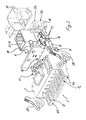
- Fig. 1 shows a connection device 1, which can be arranged, for example or on a contactor, not shown, to the power supply lines and data or control lines are to be connected.
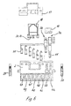
- connection device - see also Fig. 3 - according to Art designed a plug-in coupling, which has a housing 2 with a plurality first - here on the input side - connections 3a-3h and a plurality second - here on the output side - connections 4a - 4h is provided, the first connections 3a - 3h each connected to one of the second connections 4a - h in a conductive or galvanic manner are.
- first and second connections 3 and 4 used here as examples two each - the connections 3a, b and 4a, b - for connecting current and voltage supply lines (not shown here) and six each - the connections 3c - h and 4 c - h - for connecting data or control lines (also here not shown), the data lines typically being significantly smaller Have cross section than the power supply lines.
- the second or here 4 connections 4 are in a row as a socket strip 5 formed on the housing 2, each having a uniform geometry, i.e. the second power supply connections 4a, b and the second data connections 4 c - h are identical.
- first connections 3 are with respect to the first power supply connections 3a, b and the first data connections 3 c - h are designed differently.
- connection device results from the exploded views of the 3 to 6.
- the first data connections 3 c - h (not shown individually) summarized in the manner of an RJ45 socket part 18, which has side outputs here 6, each contacting conductor tracks 7 on one side of a printed circuit board 8, which is inserted into a lateral recess 9 of the housing 2.
- the conductor tracks 7 are with pads 10 on the opposite side of the circuit board 8, to which in turn tulip-like contacts 11 are soldered (e.g. in SMD technology), the tulip-like sections each in openings 12 of the socket strip 5 intervene.
- the first power supply connections 3a, b are tension spring connections 13 with stop bones 14 designed, which is facing away from the stop bone 14 End of the busbar 15 of the tension spring connections 13 directly other tulip-like contacts 11 are formed, these tulip-like power supply contacts in further of the openings 12 of the socket strip 5 engage and there the second power supply connections Form 4a, b.
- the geometry of the second data connections 4 c - h thus corresponds to the geometry the second power supply connections 4a, b.
- the standard data connector RJ45 allows a particularly uncomplicated connection the data lines without these lines having a relatively thin cross-section in tension spring connections, which are designed for conductors with a larger cross section, destroyed could become.
- RJ45 connector there would also be data connector connections other standards conceivable, e.g. serial connector, USB connector or the like.
- the first power supply connections 3a, b and the first data connections 3 c - h are framed by respective cover parts 16, 17 which can be locked on the housing 2 are.
- cover parts 16, 17 which can be locked on the housing 2 are.
- insertion openings 19a and b for operating tools formed in the area of the first power supply connections On two sides of the housing 2 there are insertion openings 19a and b for operating tools formed in the area of the first power supply connections.
Landscapes
- Coupling Device And Connection With Printed Circuit (AREA)
- Details Of Connecting Devices For Male And Female Coupling (AREA)
- Communication Control (AREA)
- Communication Cables (AREA)
Abstract
Description
- Fig. 1
- eine erste perspektivische Ansicht einer Anschlußvorrichtung;
- Fig. 2
- eine zweite perspektivische Ansicht der Anschlußvorrichtung aus Fig. 1;
- Fig. 3
- eine perspektivische Sprengansicht der Anschlußvorrichtung aus Fig. 1;
- Fig. 4
- eine zweite perspektivische Sprengansicht der Anschlußvorrichtung aus Fig. 1;
- Fig. 5
- eine dritte perspektivische Sprengansicht der Anschlußvorrichtung aus Fig. 1; und
- Fig. 6
- eine vierte Sprengansicht auf die Anschlußvorrichtung aus Fig. 1.
- Anschlußvorrichtung
- 1
- Gehäuse
- 2
- erste Anschlüsse
- 3, 3a - 3h
- zweite Anschlüsse
- 4, 4a - 4h
- Buchsenleiste
- 5
- Ausgänge
- 6
- Leiterbahnen
- 7
- Leiterplatte
- 8
- Ausnehmung
- 9
- Lötaugen
- 10
- Kontakte
- 11
- Öffnungen
- 12
- Zugfederanschlüsse
- 13
- Anschlagknochen
- 14
- Stromschiene
- 15
- Deckelteile
- 16, 17
- Buchsenteil
- 18
- Ausnehmungen
- 19a, b
- Rast-und Lösehebel
- 20
Claims (14)
- Anschlussvorrichtung zum Anschluß von Daten- und Versorgungsleitungen, insbesondere an ein elektrisches Gerät, die folgendes aufweist:dadurch gekennzeichnet, daßein Gehäuse (2),eine Mehrzahl erster Anschlüsse (3);eine Mehrzahl zweiter Anschlüsse (4);wobei die ersten und die zweiten Anschlüsse (3, 4) jeweils leitend miteinander verbunden und jeweils wenigstens einen oder mehrere Datenund Stromversorgungsanschlüsse (3a, b und 3c-h; 4a, b und 4c-h) umfassen,die ersten Anschlüsse (3) geometrisch voneinander verschiedene Datenund Stromversorgungsanschlüsse (3a, b und 3c-h) und die zweiten Anschlüsse geometrisch einheitlich ausgebildete Daten- und Stromversorgungsanschlüsse (4a, b und 4c-h) aufweisen.
- Anschlussvorrichtung nach Anspruch 1, dadurch gekennzeichnet, daß die zweiten Anschlüsse (4) in einer Reihe leistenartig am Gehäuse (2) angeordnet sind.
- Anschlussvorrichtung nach Anspruch 2, dadurch gekennzeichnet, daß die zweiten Anschlüsse (4) in einer Buchsen- oder Steckerleiste (5) oder als Lötanschlüsse am Gehäuse (2) zusammengefasst sind.
- Anschlussvorrichtung nach einem der vorstehenden Ansprüche, dadurch gekennzeichnet, daß die ersten Datenanschlüsse (3 c - h) in einem Datenstekker- oder -buchsenteil zusammengefasst sind.
- Anschlussvorrichtung nach einem der vorstehenden Ansprüche, dadurch gekennzeichnet, daß die ersten Datenanschlüsse (3 c - h) in einem RJ45-Buchsenteil (18) zusammengefasst sind.
- Anschlussvorrichtung nach einem der vorstehenden Ansprüche, dadurch gekennzeichnet, daß die ersten Stromversorgungsanschlüsse (3a, b) als Crimp-, Zugfeder-, Schraub-, IDC- oder Blattfederkontakte ausgebildet sind.
- Anschlussvorrichtung nach einem der vorstehenden Ansprüche, dadurch gekennzeichnet, daß das Buchsenteil (18) mit den ersten Datenanschlüssen (3c-h) verbundene Ausgänge (6) aufweist, die Leiterbahnen (7) auf einer Leiterplatte (8) kontaktieren.
- Anschlussvorrichtung nach einem der vorstehenden Ansprüche, dadurch gekennzeichnet, daß die Leiterbahnen (7) mit Lötaugen (10) auf der gegenüberliegenden Seite der Leiterplatte (8) verbunden sind und daß an die Lötaugen (10) tulpenartige Kontakte (11) angelötet sind.
- Anschlussvorrichtung nach einem der vorstehenden Ansprüche, dadurch gekennzeichnet, daß an die ersten Stromversorgungsanschlüsse (13) weitere der tulpenartigen Kontakte (11) angeformt sind.
- Anschlussvorrichtung nach einem der vorstehenden Ansprüche, dadurch gekennzeichnet, daß die ersten Stromversorgungsanschlüsse (3a, b) und die ersten Datenanschlüsse (3 c - h) von Deckelteilen (16, 17) eingefasst sind, die am Gehäuse 2 verrastbar sind.
- Anschlussvorrichtung nach einem der vorstehenden Ansprüche, dadurch gekennzeichnet, daß Einführöffnungen für einen RJ45 Stecker und Einführöffnungen für die Stromversorgungsleitungen an den ersten Anschlüssen (3) winklig oder parallel zueinander ausgerichtet sind.
- Anschlussvorrichtung nach einem der vorstehenden Ansprüche gekennzeichnet durch eine Auslegung als Steckkupplung für eine Stiftleiste.
- Anschlussvorrichtung nach einem der vorstehenden Ansprüche gekennzeichnet durch eine Auslegung als Stiftsteckverbinder für eine Buchsenleiste.
- Anschlussvorrichtung nach einem der vorstehenden Ansprüche gekennzeichnet durch eine Auslegung als Leiterplattenklemme, in Einpreßtechnik, in SMT-Technik, mit Lötpins oder in THR-Technik.
Applications Claiming Priority (2)
| Application Number | Priority Date | Filing Date | Title |
|---|---|---|---|
| DE20205594U | 2002-04-10 | ||
| DE20205594U DE20205594U1 (de) | 2002-04-10 | 2002-04-10 | Anschlußvorrichtung zum Anschluß von Daten- und Versorgungsleitungen an ein elektrisches Gerät |
Publications (2)
| Publication Number | Publication Date |
|---|---|
| EP1353417A1 true EP1353417A1 (de) | 2003-10-15 |
| EP1353417B1 EP1353417B1 (de) | 2007-08-29 |
Family
ID=27798368
Family Applications (1)
| Application Number | Title | Priority Date | Filing Date |
|---|---|---|---|
| EP03005507A Expired - Lifetime EP1353417B1 (de) | 2002-04-10 | 2003-03-11 | Anschlussvorrichtung zum Anschluss von Daten-und Versorgunsleitung an ein elektrisches Gerät |
Country Status (4)
| Country | Link |
|---|---|
| US (1) | US6769939B2 (de) |
| EP (1) | EP1353417B1 (de) |
| AT (1) | ATE371970T1 (de) |
| DE (2) | DE20205594U1 (de) |
Cited By (1)
| Publication number | Priority date | Publication date | Assignee | Title |
|---|---|---|---|---|
| US11196190B2 (en) | 2018-10-25 | 2021-12-07 | Hubbell Incorporated | Electrical connector |
Families Citing this family (12)
| Publication number | Priority date | Publication date | Assignee | Title |
|---|---|---|---|---|
| DE202006006626U1 (de) * | 2006-04-26 | 2007-09-06 | Weidmüller Interface GmbH & Co. KG | Verbindungs- und Schaltvorrichtung |
| ATE449438T1 (de) * | 2006-06-27 | 2009-12-15 | Weidmueller Interface | Verbindungs- und schaltvorrichtung |
| US8018735B2 (en) * | 2006-06-30 | 2011-09-13 | Siemens Industry, Inc. | Electronic module and interlocking bus system including same |
| US7367846B1 (en) * | 2007-04-24 | 2008-05-06 | Hsien-Lin Yang | Multi-function power adaptor |
| DE102007031189B4 (de) | 2007-07-04 | 2010-07-08 | Wago Verwaltungsgesellschaft Mbh | Set aus einem Gegensteckverbinder und einem Steckverbinder |
| US20110312222A1 (en) * | 2010-06-16 | 2011-12-22 | Tanaka Yokichi J | Multi-electrode holders |
| US8472167B2 (en) * | 2010-10-05 | 2013-06-25 | Ixia | High current clamping connector |
| US10479422B2 (en) | 2016-12-22 | 2019-11-19 | Polaris Industries Inc. | Side-by-side vehicle |
| BE1025734A9 (de) * | 2017-11-27 | 2019-07-03 | Phoenix Contact Gmbh & Co | Modularer Steckverbinder austauschbarer Modul-Leiterplatte |
| NO347622B1 (en) * | 2021-02-05 | 2024-01-29 | Zaptec Ip As | Input connector with integrated residual current detection |
| USD1067123S1 (en) | 2023-01-20 | 2025-03-18 | Polaris Industries Inc. | Off-road vehicle |
| USD1120805S1 (en) | 2023-06-29 | 2026-03-31 | Polaris Industries Inc. | Body assembly for an off-road vehicle |
Citations (3)
| Publication number | Priority date | Publication date | Assignee | Title |
|---|---|---|---|---|
| US6027375A (en) * | 1998-09-11 | 2000-02-22 | Hon Hai Precision Ind. Co., Ltd. | Electrical connection device |
| EP1139503A2 (de) * | 2000-03-28 | 2001-10-04 | Matsushita Electric Industrial Co., Ltd. | Verbindungskabelvorrichtung |
| EP1156556A2 (de) * | 2000-05-19 | 2001-11-21 | Delphi Technologies, Inc. | Verbindungsmodul |
Family Cites Families (11)
| Publication number | Priority date | Publication date | Assignee | Title |
|---|---|---|---|---|
| CH628484A5 (de) * | 1978-04-21 | 1982-02-26 | Erni & Co Elektro Ind | Verfahren und kontaktleiste zur herstellung gasdichter verbindungen fuer eine gedruckte rueckwandverdrahtung. |
| DE29502186U1 (de) * | 1995-02-10 | 1995-03-30 | Weidmüller Interface GmbH & Co, 32760 Detmold | Elektrische Verteileranordnung |
| US5741161A (en) * | 1996-01-04 | 1998-04-21 | Pcd Inc. | Electrical connection system with discrete wire interconnections |
| US5713766A (en) * | 1996-03-21 | 1998-02-03 | Axsys Technologies | Depluggable barrier terminal strips |
| US6074255A (en) * | 1998-02-23 | 2000-06-13 | Dekko Engineering, Inc. | Communication system and communication cable connector assembly |
| US6074241A (en) * | 1998-06-05 | 2000-06-13 | The Whitaker Corporation | Non-slip spring clamp contact |
| US6325675B1 (en) * | 2000-01-14 | 2001-12-04 | Ilsco Corporation | Electrical-connector insulating cover having a hinged access cover |
| US6238234B1 (en) * | 2000-02-26 | 2001-05-29 | Marconi Communications, Inc. | Terminal block with reduced dielectric material |
| DE20006280U1 (de) * | 2000-04-05 | 2000-08-03 | Honeywell Ag, 63067 Offenbach | Adapter |
| US6553433B1 (en) * | 2000-04-12 | 2003-04-22 | Cheng-Chun Chang | IDE interface adapter |
| DE10108948C2 (de) * | 2001-02-23 | 2003-04-10 | Siemens Ag | Steckverbindung |
-
2002
- 2002-04-10 DE DE20205594U patent/DE20205594U1/de not_active Expired - Lifetime
-
2003
- 2003-03-11 EP EP03005507A patent/EP1353417B1/de not_active Expired - Lifetime
- 2003-03-11 AT AT03005507T patent/ATE371970T1/de not_active IP Right Cessation
- 2003-03-11 DE DE50308041T patent/DE50308041D1/de not_active Expired - Fee Related
- 2003-04-07 US US10/407,206 patent/US6769939B2/en not_active Expired - Fee Related
Patent Citations (3)
| Publication number | Priority date | Publication date | Assignee | Title |
|---|---|---|---|---|
| US6027375A (en) * | 1998-09-11 | 2000-02-22 | Hon Hai Precision Ind. Co., Ltd. | Electrical connection device |
| EP1139503A2 (de) * | 2000-03-28 | 2001-10-04 | Matsushita Electric Industrial Co., Ltd. | Verbindungskabelvorrichtung |
| EP1156556A2 (de) * | 2000-05-19 | 2001-11-21 | Delphi Technologies, Inc. | Verbindungsmodul |
Cited By (2)
| Publication number | Priority date | Publication date | Assignee | Title |
|---|---|---|---|---|
| US11196190B2 (en) | 2018-10-25 | 2021-12-07 | Hubbell Incorporated | Electrical connector |
| US11764496B2 (en) | 2018-10-25 | 2023-09-19 | Hubbell Incorporated | Electrical connector and method therefore |
Also Published As
| Publication number | Publication date |
|---|---|
| EP1353417B1 (de) | 2007-08-29 |
| DE20205594U1 (de) | 2003-08-28 |
| ATE371970T1 (de) | 2007-09-15 |
| US6769939B2 (en) | 2004-08-03 |
| DE50308041D1 (de) | 2007-10-11 |
| US20030224665A1 (en) | 2003-12-04 |
Similar Documents
| Publication | Publication Date | Title |
|---|---|---|
| DE102008026471B3 (de) | Verbindungselement zur Herstellung einer elektrisch leitenden Verbindung zwischen zwei Anschlussklemmen | |
| DE69517854T2 (de) | Elektrischer Verbinder für Stromleiter | |
| EP3794684B1 (de) | Leiterkartensteckverbindung | |
| EP1868264B1 (de) | Anschlussleiste mit Kodiervorrichtung | |
| DE19527751A1 (de) | Verbinder für ein Kabel | |
| EP1353417B1 (de) | Anschlussvorrichtung zum Anschluss von Daten-und Versorgunsleitung an ein elektrisches Gerät | |
| EP3698438B1 (de) | Vorrichtung zur elektrischen kontaktierung | |
| DE4222685C2 (de) | Steckkontaktelement | |
| DE68919912T2 (de) | Kontaktverbinder für Schaltplatte. | |
| DE29821211U1 (de) | Steckverbinderkontakt mit Schneidanschluß | |
| EP0373709B1 (de) | Vorrichtung zum Anschluss eines Koaxialkabels | |
| DE19921021A1 (de) | Leiterplatten-Steckverbinder | |
| DE102006030712B4 (de) | Steckverbinder | |
| DE4111956A1 (de) | Mehrpolige elektrische anschlussvorrichtung | |
| EP3743962A1 (de) | Leiterkartenverbinder zur übertragung hoher stromstärken | |
| EP4250498A1 (de) | Kontaktelement, kontaktelementsystem und steckverbinder | |
| DE10108948A1 (de) | Steckverbindung | |
| DE102006020045B4 (de) | Zwischenstecker und Verfahren zur Herstellung eines Zwischensteckers | |
| DE10113063B4 (de) | Elektrische Anschluss- oder Verbindungsklemme | |
| DE10328659B4 (de) | Elektrische Verbindungsanordnung | |
| LU500693B1 (de) | Steckverbinderteil mit einer Schirmauflage | |
| DE102008051286B4 (de) | Kontaktiereinrichtung für Leiterplatten | |
| CH627305A5 (en) | Male strip connector having plug contacts. | |
| EP0895660A1 (de) | Kabelsteckverbinder mit in einem isolationskörper befestigten kontaktbahnen mit lötanschlüssen | |
| EP2581990B1 (de) | Gehäuse für eine Telekommunikationsvorrichtung |
Legal Events
| Date | Code | Title | Description |
|---|---|---|---|
| PUAI | Public reference made under article 153(3) epc to a published international application that has entered the european phase |
Free format text: ORIGINAL CODE: 0009012 |
|
| AK | Designated contracting states |
Kind code of ref document: A1 Designated state(s): AT BE BG CH CY CZ DE DK EE ES FI FR GB GR HU IE IT LI LU MC NL PT RO SE SI SK TR |
|
| AX | Request for extension of the european patent |
Extension state: AL LT LV MK |
|
| 17P | Request for examination filed |
Effective date: 20030926 |
|
| 17Q | First examination report despatched |
Effective date: 20031218 |
|
| AKX | Designation fees paid |
Designated state(s): AT BE BG CH CY CZ DE DK EE ES FI FR GB GR HU IE IT LI LU MC NL PT RO SE SI SK TR |
|
| GRAP | Despatch of communication of intention to grant a patent |
Free format text: ORIGINAL CODE: EPIDOSNIGR1 |
|
| GRAS | Grant fee paid |
Free format text: ORIGINAL CODE: EPIDOSNIGR3 |
|
| GRAA | (expected) grant |
Free format text: ORIGINAL CODE: 0009210 |
|
| AK | Designated contracting states |
Kind code of ref document: B1 Designated state(s): AT BE BG CH CY CZ DE DK EE ES FI FR GB GR HU IE IT LI LU MC NL PT RO SE SI SK TR |
|
| REG | Reference to a national code |
Ref country code: GB Ref legal event code: FG4D Free format text: NOT ENGLISH |
|
| REG | Reference to a national code |
Ref country code: CH Ref legal event code: EP |
|
| REG | Reference to a national code |
Ref country code: IE Ref legal event code: FG4D Free format text: LANGUAGE OF EP DOCUMENT: GERMAN |
|
| REF | Corresponds to: |
Ref document number: 50308041 Country of ref document: DE Date of ref document: 20071011 Kind code of ref document: P |
|
| PG25 | Lapsed in a contracting state [announced via postgrant information from national office to epo] |
Ref country code: ES Free format text: LAPSE BECAUSE OF FAILURE TO SUBMIT A TRANSLATION OF THE DESCRIPTION OR TO PAY THE FEE WITHIN THE PRESCRIBED TIME-LIMIT Effective date: 20071210 Ref country code: NL Free format text: LAPSE BECAUSE OF FAILURE TO SUBMIT A TRANSLATION OF THE DESCRIPTION OR TO PAY THE FEE WITHIN THE PRESCRIBED TIME-LIMIT Effective date: 20070829 Ref country code: FI Free format text: LAPSE BECAUSE OF FAILURE TO SUBMIT A TRANSLATION OF THE DESCRIPTION OR TO PAY THE FEE WITHIN THE PRESCRIBED TIME-LIMIT Effective date: 20070829 |
|
| NLV1 | Nl: lapsed or annulled due to failure to fulfill the requirements of art. 29p and 29m of the patents act | ||
| GBV | Gb: ep patent (uk) treated as always having been void in accordance with gb section 77(7)/1977 [no translation filed] |
Effective date: 20070829 |
|
| REG | Reference to a national code |
Ref country code: IE Ref legal event code: FD4D |
|
| EN | Fr: translation not filed | ||
| PG25 | Lapsed in a contracting state [announced via postgrant information from national office to epo] |
Ref country code: GR Free format text: LAPSE BECAUSE OF FAILURE TO SUBMIT A TRANSLATION OF THE DESCRIPTION OR TO PAY THE FEE WITHIN THE PRESCRIBED TIME-LIMIT Effective date: 20071130 Ref country code: DK Free format text: LAPSE BECAUSE OF FAILURE TO SUBMIT A TRANSLATION OF THE DESCRIPTION OR TO PAY THE FEE WITHIN THE PRESCRIBED TIME-LIMIT Effective date: 20070829 |
|
| PG25 | Lapsed in a contracting state [announced via postgrant information from national office to epo] |
Ref country code: SK Free format text: LAPSE BECAUSE OF FAILURE TO SUBMIT A TRANSLATION OF THE DESCRIPTION OR TO PAY THE FEE WITHIN THE PRESCRIBED TIME-LIMIT Effective date: 20070829 Ref country code: IE Free format text: LAPSE BECAUSE OF FAILURE TO SUBMIT A TRANSLATION OF THE DESCRIPTION OR TO PAY THE FEE WITHIN THE PRESCRIBED TIME-LIMIT Effective date: 20070829 Ref country code: PT Free format text: LAPSE BECAUSE OF FAILURE TO SUBMIT A TRANSLATION OF THE DESCRIPTION OR TO PAY THE FEE WITHIN THE PRESCRIBED TIME-LIMIT Effective date: 20080129 Ref country code: GB Free format text: LAPSE BECAUSE OF FAILURE TO SUBMIT A TRANSLATION OF THE DESCRIPTION OR TO PAY THE FEE WITHIN THE PRESCRIBED TIME-LIMIT Effective date: 20070829 Ref country code: CZ Free format text: LAPSE BECAUSE OF FAILURE TO SUBMIT A TRANSLATION OF THE DESCRIPTION OR TO PAY THE FEE WITHIN THE PRESCRIBED TIME-LIMIT Effective date: 20070829 |
|
| PG25 | Lapsed in a contracting state [announced via postgrant information from national office to epo] |
Ref country code: SE Free format text: LAPSE BECAUSE OF FAILURE TO SUBMIT A TRANSLATION OF THE DESCRIPTION OR TO PAY THE FEE WITHIN THE PRESCRIBED TIME-LIMIT Effective date: 20071129 Ref country code: RO Free format text: LAPSE BECAUSE OF FAILURE TO SUBMIT A TRANSLATION OF THE DESCRIPTION OR TO PAY THE FEE WITHIN THE PRESCRIBED TIME-LIMIT Effective date: 20070829 |
|
| PLBE | No opposition filed within time limit |
Free format text: ORIGINAL CODE: 0009261 |
|
| STAA | Information on the status of an ep patent application or granted ep patent |
Free format text: STATUS: NO OPPOSITION FILED WITHIN TIME LIMIT |
|
| 26N | No opposition filed |
Effective date: 20080530 |
|
| BERE | Be: lapsed |
Owner name: WEIDMULLER INTERFACE G.M.B.H. & CO. Effective date: 20080331 |
|
| PG25 | Lapsed in a contracting state [announced via postgrant information from national office to epo] |
Ref country code: MC Free format text: LAPSE BECAUSE OF NON-PAYMENT OF DUE FEES Effective date: 20080331 |
|
| REG | Reference to a national code |
Ref country code: CH Ref legal event code: PL |
|
| PG25 | Lapsed in a contracting state [announced via postgrant information from national office to epo] |
Ref country code: CH Free format text: LAPSE BECAUSE OF NON-PAYMENT OF DUE FEES Effective date: 20080331 Ref country code: EE Free format text: LAPSE BECAUSE OF FAILURE TO SUBMIT A TRANSLATION OF THE DESCRIPTION OR TO PAY THE FEE WITHIN THE PRESCRIBED TIME-LIMIT Effective date: 20070829 Ref country code: LI Free format text: LAPSE BECAUSE OF NON-PAYMENT OF DUE FEES Effective date: 20080331 Ref country code: DE Free format text: LAPSE BECAUSE OF NON-PAYMENT OF DUE FEES Effective date: 20081001 |
|
| PG25 | Lapsed in a contracting state [announced via postgrant information from national office to epo] |
Ref country code: BE Free format text: LAPSE BECAUSE OF NON-PAYMENT OF DUE FEES Effective date: 20080331 |
|
| PG25 | Lapsed in a contracting state [announced via postgrant information from national office to epo] |
Ref country code: SI Free format text: LAPSE BECAUSE OF FAILURE TO SUBMIT A TRANSLATION OF THE DESCRIPTION OR TO PAY THE FEE WITHIN THE PRESCRIBED TIME-LIMIT Effective date: 20070829 |
|
| PG25 | Lapsed in a contracting state [announced via postgrant information from national office to epo] |
Ref country code: CY Free format text: LAPSE BECAUSE OF FAILURE TO SUBMIT A TRANSLATION OF THE DESCRIPTION OR TO PAY THE FEE WITHIN THE PRESCRIBED TIME-LIMIT Effective date: 20070829 |
|
| PG25 | Lapsed in a contracting state [announced via postgrant information from national office to epo] |
Ref country code: BG Free format text: LAPSE BECAUSE OF FAILURE TO SUBMIT A TRANSLATION OF THE DESCRIPTION OR TO PAY THE FEE WITHIN THE PRESCRIBED TIME-LIMIT Effective date: 20071129 Ref country code: AT Free format text: LAPSE BECAUSE OF NON-PAYMENT OF DUE FEES Effective date: 20080311 |
|
| PG25 | Lapsed in a contracting state [announced via postgrant information from national office to epo] |
Ref country code: LU Free format text: LAPSE BECAUSE OF NON-PAYMENT OF DUE FEES Effective date: 20080311 Ref country code: HU Free format text: LAPSE BECAUSE OF FAILURE TO SUBMIT A TRANSLATION OF THE DESCRIPTION OR TO PAY THE FEE WITHIN THE PRESCRIBED TIME-LIMIT Effective date: 20080301 |
|
| PG25 | Lapsed in a contracting state [announced via postgrant information from national office to epo] |
Ref country code: TR Free format text: LAPSE BECAUSE OF FAILURE TO SUBMIT A TRANSLATION OF THE DESCRIPTION OR TO PAY THE FEE WITHIN THE PRESCRIBED TIME-LIMIT Effective date: 20070829 |
|
| PG25 | Lapsed in a contracting state [announced via postgrant information from national office to epo] |
Ref country code: IT Free format text: LAPSE BECAUSE OF NON-PAYMENT OF DUE FEES Effective date: 20080331 |
|
| PG25 | Lapsed in a contracting state [announced via postgrant information from national office to epo] |
Ref country code: FR Free format text: LAPSE BECAUSE OF FAILURE TO SUBMIT A TRANSLATION OF THE DESCRIPTION OR TO PAY THE FEE WITHIN THE PRESCRIBED TIME-LIMIT Effective date: 20080425 |