EP1353036A2 - Parclose et agencement de cadre - Google Patents
Parclose et agencement de cadre Download PDFInfo
- Publication number
- EP1353036A2 EP1353036A2 EP03008248A EP03008248A EP1353036A2 EP 1353036 A2 EP1353036 A2 EP 1353036A2 EP 03008248 A EP03008248 A EP 03008248A EP 03008248 A EP03008248 A EP 03008248A EP 1353036 A2 EP1353036 A2 EP 1353036A2
- Authority
- EP
- European Patent Office
- Prior art keywords
- glass
- frame
- strip
- seal
- holding
- Prior art date
- Legal status (The legal status is an assumption and is not a legal conclusion. Google has not performed a legal analysis and makes no representation as to the accuracy of the status listed.)
- Withdrawn
Links
Images

Classifications
-
- E—FIXED CONSTRUCTIONS
- E06—DOORS, WINDOWS, SHUTTERS, OR ROLLER BLINDS IN GENERAL; LADDERS
- E06B—FIXED OR MOVABLE CLOSURES FOR OPENINGS IN BUILDINGS, VEHICLES, FENCES OR LIKE ENCLOSURES IN GENERAL, e.g. DOORS, WINDOWS, BLINDS, GATES
- E06B3/00—Window sashes, door leaves, or like elements for closing wall or like openings; Layout of fixed or moving closures, e.g. windows in wall or like openings; Features of rigidly-mounted outer frames relating to the mounting of wing frames
- E06B3/54—Fixing of glass panes or like plates
- E06B3/58—Fixing of glass panes or like plates by means of borders, cleats, or the like
- E06B3/5807—Fixing of glass panes or like plates by means of borders, cleats, or the like not adjustable
- E06B3/5821—Fixing of glass panes or like plates by means of borders, cleats, or the like not adjustable hooked on or in the frame member, fixed by clips or otherwise elastically fixed
- E06B3/5828—Fixing of glass panes or like plates by means of borders, cleats, or the like not adjustable hooked on or in the frame member, fixed by clips or otherwise elastically fixed on or with auxiliary pieces
- E06B3/5835—Fixing of glass panes or like plates by means of borders, cleats, or the like not adjustable hooked on or in the frame member, fixed by clips or otherwise elastically fixed on or with auxiliary pieces together with parts of the border in the same undercut groove in the frame
Definitions
- the present invention relates to a glass retaining strip, in particular for fixing a filling element, such as a glass pane on a frame, with a first Leg, which has a first holding element at one end portion, at one Glass seal is retractable, and at least one foot section that on one Frame profile can be determined, and a frame arrangement with a glass retaining strip.
- a filling element such as a glass pane on a frame
- a first Leg which has a first holding element at one end portion, at one Glass seal is retractable, and at least one foot section that on one Frame profile can be determined
- a second leg has, on which a second holding element for receiving a seal between Glass retaining strip and frame profile is also provided on the side to the Frame profile sealing can be achieved in a safe way to prevent penetration to prevent moisture in the rebate area. It also prevents water penetrated through the gap between the glazing bead and the frame profile can leak.
- the foot section is preferably in a groove or receptacle can be used on the frame profile, so that the glass retaining strip in one direction is securely supported perpendicular to the plane of the pane.
- the first and the second holding element arranged on opposite sides of the glass holding strip, so that the way from the filling element to the frame profile with the glass retaining strip is bridged and the glass holding strip can be made compact.
- the first and / or that second holding element are the first and / or that second holding element as a groove, possibly formed as an undercut groove.
- a frame opposite the second holding element is preferably adjacent Contact surface provided.
- the seal is between Frame profile and glass retaining bar not visible, although it is possible to also To use the contact surface as a sealing area, in order to avoid damp and soiling Avoid cavities or gaps on the glazing bead.
- the contact surface also serves to support the force, since the glass holding bar essentially by the on the filling element seal in a direction perpendicular to Disk level is pressed. The contact surface can thus be supported Form pivot point.
- a foot section with at least one is on the glass retaining strip molded onto a web that can be supported on the frame profile. Further the glass retaining strip can be fixed to the frame profile by means of mounting means, so that no complex tools have to be used for assembly.
- the foot section can extend in two directions Have webs, each of which can be placed on or in receptacles on the frame profile are. A web is supported in a direction perpendicular to the plane of the pane, so that a transfer of force through compression by this web the forces arising on the glass pane are reached can.
- a frame arrangement for windows, doors, facades or light roofs provided in the between the glass retaining bar and frame profile another seal for sealing the interior between the filling element and frame is provided.
- the seal is for a permanent seal between the glass retaining strip and Frame profile drawn into a groove in the glass retaining strip and lies with one slight compression on a contact surface of the frame profile.
- the seal for example, a compressible hollow chamber and / or a Have a sealing lip.
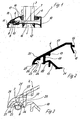
- a cross section of a frame profile 1 is shown, which consists of an extruded aluminum profile is formed and an outer shell 10, an inner shell 11 and insulating webs 12 made of plastic for thermal insulation.
- Multiple frame profiles 1 are assembled into a frame and surround a glass pane 3 as a filling element.
- a Stop 2 is provided, in which a system seal 4 is inserted. The glass pane 3 abuts the contact seal 4 all around in the assembled state.
- a glass holding strip 6 is used for further assembly of a finished frame arrangement inserted into a groove 9 of the frame profile 1.
- the glass holding strip 6 has one for this Foot section 13, which is inserted into a groove 9 formed on the frame profile 1 is.
- a holder 7 provided between the between the groove 9 and the foot portion 13 of the Glass holding bar 6 is used.
- the glass holding strip 6 has a first leg 17 on which a glass seal 5 is used.
- the glass seal 5 provides a seal between the glass retaining strip 6 and the glass pane 3.
- a thickened projection on the leg 17 16 provided, which engages in a groove on the glass seal 5, the Glass seal 5 on the side facing away from the glass pane 3 through an end section 15 is supported. It is also possible to the glass seal 5 in a groove Retract leg 17.
- a leg 18 is formed on the opposite side of the glass holding strip 6, which is directed to an edge region of the frame profile 1.
- the shape of the Legs 17 and 18 are visible from the outside and can be varied as required. For example, instead of straight legs 17 and 18, rounded legs can be used become.
- the so-called glass rebate 14 To prevent this glass rebate 14
- the glass retaining strip has moisture that can penetrate from inside or outside 6 a holding element for fixing an elastic seal 8 between the Glass retaining strip 6 and the frame profile 1.
- the glass holding strip 6 has a groove 22, into which a seal is retractable.
- the groove 22 is undercut and has side projections 23 and 24 for securely holding a foot one Poetry.
- a groove bottom 25 is formed on the leg 18, which acts as a stop can serve for a seal.
- the foot section 13 of the glass retaining strip 6 has a first web 20, which is on the side can be applied to a projection of the groove 9. Furthermore, a second is oblique to that first web 20 extending web 21 is provided with an angled end, which of the opposite side wall of the groove 9 is partially encompassed.
- the glass holding strip 6 comprises a holding web 19 with a projection which is simple Attachment of the holder 7 is used.
- a contact surface 27 is formed on the leg 18 at an end section 26, which rests on the frame profile 1, or a small gap to the frame profile 1 can train. Through the end portion 26, the seal 8 is from the outside not visible.
- Fig. 3 the area of the seal 8 is shown enlarged.
- the seal 8 has a foot portion 32 on which two shoulders 28 and 29 are formed, the are held in the groove 22 by the projections 23 and 24.
- the foot section 32 can rest on the groove bottom 25, so that the seal 8 is supported in the groove 22 is held.
- the seal 8 is provided with a hollow chamber 30, which makes the seal 8 special is elastic.
- the seal 8 has a facing the frame profile 1 rounded contact surface 31, which protrudes beyond the contact surface 27 of the glass retaining strip 6. In the installed state, the seal 8 lies against the contact surface 31 the frame profile 1 with a certain compression to seal the gap between frame profile 1 and glass retaining strip 6, so that no moisture in the glass rebate 14 can penetrate.
- Fig. 4 is the glass retaining strip 6 of the first embodiment with a seal 8 ', which in turn has a foot section 32 with two shoulders 28 and 29 has, which engages in the groove 22.
- the sealing surface protruding downwards is formed by a sealing lip 36 which abut a surface of the frame profile 1 can.
- a seal 8 " is in the glass retaining strip 6 retracted, which in turn held with a foot portion 32 in the groove 22 is.
- the seal 8 " has a plurality of tips 37 and grooves which form a sealing surface train to rest on the frame profile 1.
- Fig. 6 is a seal 8 "'with a foot portion 32 in the groove 22 of the glass retaining strip 6 moved in.
- the seal 8 "' has a sealing lip 39, which is below the support surface 27 of the glass retaining strip 6 the gap between the support surface 27 and frame profile 1 and is therefore slightly visible from the outside. hereby is achieved by compressing the sealing lip 39 between the bearing surface 27 and the frame profile 1 a seal already in the area of the support surface 27 reached.
- a curvature 38 is provided, which has a further sealing surface on the frame profile 1 trains.
- the frame profile 1 is made of a thermally insulated Formed aluminum profile. It is also possible for the frame Use plastic or wooden profiles or profiles made of another material.
- a mountable glass retaining strip can also be provided on both sides.
- the term "Glass holding strip” is used to cover the usual application of this component to make it clear. Nevertheless, such a “glass holding strip” can also be used Definition of other filling elements, for example made of plastic or others Materials are used.
- the glass retaining strips shown are on the frame profile via clamping elements fixed. It is also possible within the scope of the invention to fasten other fastening means use, for example screws, nails, locking means or other clamping and Holding devices.
Landscapes
- Engineering & Computer Science (AREA)
- Civil Engineering (AREA)
- Structural Engineering (AREA)
- Securing Of Glass Panes Or The Like (AREA)
Applications Claiming Priority (2)
| Application Number | Priority Date | Filing Date | Title |
|---|---|---|---|
| DE20205669U | 2002-04-12 | ||
| DE20205669U DE20205669U1 (de) | 2002-04-12 | 2002-04-12 | Glashalteleiste und Rahmenanordnung |
Publications (2)
| Publication Number | Publication Date |
|---|---|
| EP1353036A2 true EP1353036A2 (fr) | 2003-10-15 |
| EP1353036A3 EP1353036A3 (fr) | 2004-09-15 |
Family
ID=7969942
Family Applications (1)
| Application Number | Title | Priority Date | Filing Date |
|---|---|---|---|
| EP03008248A Withdrawn EP1353036A3 (fr) | 2002-04-12 | 2003-04-09 | Parclose et agencement de cadre |
Country Status (2)
| Country | Link |
|---|---|
| EP (1) | EP1353036A3 (fr) |
| DE (1) | DE20205669U1 (fr) |
Family Cites Families (4)
| Publication number | Priority date | Publication date | Assignee | Title |
|---|---|---|---|---|
| US4207717A (en) * | 1978-10-18 | 1980-06-17 | Kawneer Company, Inc. | System for improving heat insulating characteristics of existing curtain walls and the like |
| DE3500927A1 (de) * | 1985-01-12 | 1986-07-17 | Glos, Georg, 8700 Würzburg | Vorrichtung zum befestigen von glasscheiben o.dgl. |
| DE3912136A1 (de) * | 1989-04-13 | 1990-10-18 | Lanco Lange Fenster Fassaden | Festverglastes holz/metall-fenster |
| DE9321024U1 (de) * | 1993-02-26 | 1995-11-16 | Schüco International KG, 33609 Bielefeld | Kunststoffhalter zur Festlegung einer Halteleiste für eine Glasscheibe oder eine Füllungsplatte an einem Rahmen eines Fensters oder einer Tür |
-
2002
- 2002-04-12 DE DE20205669U patent/DE20205669U1/de not_active Expired - Lifetime
-
2003
- 2003-04-09 EP EP03008248A patent/EP1353036A3/fr not_active Withdrawn
Also Published As
| Publication number | Publication date |
|---|---|
| DE20205669U1 (de) | 2002-07-04 |
| EP1353036A3 (fr) | 2004-09-15 |
Similar Documents
| Publication | Publication Date | Title |
|---|---|---|
| DE4309088A1 (de) | Ortsfest einbaubare Scheibe für Kraftfahrzeuge | |
| DE19601505C1 (de) | Glasrandhalterung | |
| EP1020579B1 (fr) | Feuillures de façade ou toiture vitrée avec profilé d'étanchéité | |
| EP0692586B2 (fr) | Façade | |
| EP2327855B1 (fr) | Unité de verre isolant et construction de support dotée d'au moins une telle unité de verre isolant | |
| DE102012112279A1 (de) | Fassade oder Lichtdach, Isoliersteg und Verfahren zum Herstellen eines Isoliersteges | |
| DE2951185A1 (de) | Vorrichtung zum neuverglasen von insbesondere holzfenstern | |
| EP2746515A2 (fr) | Panneau d'habillage pour une structure de fenêtre ou de porte | |
| DE7732328U1 (de) | Rahmen fuer fenster, tueren u.dgl. mit metall-verblendprofil | |
| DE29517566U1 (de) | Verkleidung für Fenster oder Türen | |
| DE10140708A1 (de) | Sicherheitsglasfalzeinlage/Sicherheitsverglasungsklotz | |
| EP4198243B1 (fr) | Agencement de profilé de cadre | |
| EP0524631B1 (fr) | Dispositif pour monter des vitrages isolants | |
| EP1353036A2 (fr) | Parclose et agencement de cadre | |
| DE202013100101U1 (de) | Wärmedämmleiste und Rahmenprofil für ein Fenster, eine Tür, eine Fassade oder ein Lichtdach | |
| DE29900650U1 (de) | Dichtungsanordnung für Fenster und Türen | |
| WO1996018018A1 (fr) | Dispositif de fixation | |
| DE29716361U1 (de) | Gebäudefenster und/oder Gebäudefenstertür | |
| EP0458191B1 (fr) | Revêtement de bord pour rebords de fenêtre ou des choses pareilles | |
| DE3528388A1 (de) | Elastische profildichtung fuer isolierverglasungen | |
| DE3015822A1 (de) | Fenster, dessen rahmen metall- und kunststoffprofilteile aufweisen | |
| DE202018104841U1 (de) | Verschlusselement zum Verschließen einer Öffnung | |
| DE3700201A1 (de) | Justiervorrichtung zum ausrichten von tuerrahmen, fensterblendrahmen oder dergleichen in einer bauoeffnung | |
| DE19622725C2 (de) | Gebäudefenster und/oder Gebäudefenstertür | |
| EP3385487A1 (fr) | Élément de remplissage pour une façade ou une porte |
Legal Events
| Date | Code | Title | Description |
|---|---|---|---|
| PUAI | Public reference made under article 153(3) epc to a published international application that has entered the european phase |
Free format text: ORIGINAL CODE: 0009012 |
|
| AK | Designated contracting states |
Kind code of ref document: A2 Designated state(s): AT BE BG CH CY CZ DE DK EE ES FI FR GB GR HU IE IT LI LU MC NL PT RO SE SI SK TR |
|
| AX | Request for extension of the european patent |
Extension state: AL LT LV MK |
|
| RIN1 | Information on inventor provided before grant (corrected) |
Inventor name: BUDDE, RALF |
|
| PUAL | Search report despatched |
Free format text: ORIGINAL CODE: 0009013 |
|
| AK | Designated contracting states |
Kind code of ref document: A3 Designated state(s): AT BE BG CH CY CZ DE DK EE ES FI FR GB GR HU IE IT LI LU MC NL PT RO SE SI SK TR |
|
| AX | Request for extension of the european patent |
Extension state: AL LT LV MK |
|
| AKX | Designation fees paid | ||
| REG | Reference to a national code |
Ref country code: DE Ref legal event code: 8566 |
|
| STAA | Information on the status of an ep patent application or granted ep patent |
Free format text: STATUS: THE APPLICATION IS DEEMED TO BE WITHDRAWN |
|
| 18D | Application deemed to be withdrawn |
Effective date: 20050316 |