EP1352777A1 - Collecteur de courant - Google Patents
Collecteur de courant Download PDFInfo
- Publication number
- EP1352777A1 EP1352777A1 EP02027757A EP02027757A EP1352777A1 EP 1352777 A1 EP1352777 A1 EP 1352777A1 EP 02027757 A EP02027757 A EP 02027757A EP 02027757 A EP02027757 A EP 02027757A EP 1352777 A1 EP1352777 A1 EP 1352777A1
- Authority
- EP
- European Patent Office
- Prior art keywords
- motion sensor
- pantograph
- current collector
- conductor
- sensor
- Prior art date
- Legal status (The legal status is an assumption and is not a legal conclusion. Google has not performed a legal analysis and makes no representation as to the accuracy of the status listed.)
- Withdrawn
Links
Images


Classifications
-
- B—PERFORMING OPERATIONS; TRANSPORTING
- B60—VEHICLES IN GENERAL
- B60L—PROPULSION OF ELECTRICALLY-PROPELLED VEHICLES; SUPPLYING ELECTRIC POWER FOR AUXILIARY EQUIPMENT OF ELECTRICALLY-PROPELLED VEHICLES; ELECTRODYNAMIC BRAKE SYSTEMS FOR VEHICLES IN GENERAL; MAGNETIC SUSPENSION OR LEVITATION FOR VEHICLES; MONITORING OPERATING VARIABLES OF ELECTRICALLY-PROPELLED VEHICLES; ELECTRIC SAFETY DEVICES FOR ELECTRICALLY-PROPELLED VEHICLES
- B60L5/00—Current collectors for power supply lines of electrically-propelled vehicles
- B60L5/38—Current collectors for power supply lines of electrically-propelled vehicles for collecting current from conductor rails
Definitions
- the invention relates to a pantograph for a Conductor rail with at least one housing and at least one accommodated by a housing Contact line contact from an electrical conductive material.
- Such pantographs are, for example in conveyor systems such as electric monorails or electric trams used. In these Contact line systems must have the contact line contacts if possible always contact to the conductor rail have a reliable power transmission guaranteed to mobile consumers.
- pantographs known from practice occur Faults in the contact between the pantograph and the conductor rail often at switch junctions, joint junctions or due to a broken pantograph or due to defective rail connectors. With significant Malfunctions can result in longer downtimes his. It is therefore desirable that interference with the Conductor conductor busbars or in the conductor rail route of Pantographs are recognized in a timely and preventive manner, so that remedial action can be taken.
- the invention is based on the technical problem Specify pantographs of the type mentioned, with the Faults on the conductor rail or in Current collector conductor line and reliable can be effectively recognized in time.
- the invention teaches to solve this technical problem a pantograph of the type mentioned, which is characterized in that on the pantograph at least one motion sensor is provided with which Motion sensor deflections due to the pantograph of irregularities in its conductor line are.
- the pantograph according to the invention can, for example, as Single arm grinder, double contact grinder, double current collector or double-arm grinder.
- the pantograph can have a contact line contact or also preferably two contact line contacts.
- the invention is based on the finding that with a motion sensor according to the invention on the pantograph Irregularities on the conductor rail or be reliably identified in the conductor line can.
- the invention is also based on the knowledge based on the irregularities in the conductor rail path Impacts or impacts on the pantograph or on the Generate conductor rail contacts of pantographs that can be detected effectively with a motion sensor. Such impacts occur, for example, through misalignment at joints, at non-aligned transitions of the conductor rail or by torn pantographs or on defective rail connectors.
- Pantographs can easily make irregularities or faults in the conductor line early are recognized, so that by appropriate maintenance or Repair measures remedied in time can be.
- the motion sensor is a biaxial acceleration sensor. With this motion sensor, deflections can or accelerations with respect to two spatial axes become. This motion sensor has become part of the Invention particularly proven.
- an electronic Evaluation device which from Motion sensor detected deflections in the form of deflection signals are feedable. Appropriately acts the deflection signals are voltage signals, the supplied to the electronic evaluation device become. It is within the scope of the invention that Voltage proportional to the deflection or acceleration is.
- the electronic Evaluation device directly on the pantograph for example, be attached to the receiving housing.
- the electronic Evaluation device arranged outside the pantograph and the motion sensor is conveniently over a flexible cable to the electronic evaluation device connected. It is within the scope of the invention that the electronic evaluation device digital Sends signals to a control and / or regulating device.
- the control and / or regulating device is expedient equipped with a microcomputer to which the digital signals.
- a microcomputer to which the digital signals.
- said deflection maximum is adjustable or specifiable. So if the pantograph according to the invention with an impact certain magnitude is applied, the Control and / or regulating device an alarm signal.
- the Motion sensor picked up by the receiving housing can be in a pocket-shaped receptacle of the receiving housing can be arranged. It is in the Framework of the invention that the motion sensor only is inserted, or via a snap connection is attached. - According to another embodiment of the Invention is the motion sensor on the conductor line contact attached. The motion sensor can, for example be glued to the conductor line contact.
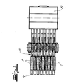
- Fig. 1 shows a top view of a pantograph unit from a plurality of arranged side by side Pantograph 1, the one not shown Conductor conductor rail are assigned.
- the Current collectors 1 is also a current collector according to the invention 1 'with connected motion sensor 2.
- Fig. 2 shows the individual pantograph according to the invention 1 'with the motion sensor 2 in a side view.
- This Current collector 1 ' has a receiving housing 3 with one of the receiving housing 3 recorded conductor line contact 4 made of an electrically conductive material.
- the receptacle 3 is springy in a conventional manner a parallelogram linkage 5 held.
- the power supply of the conductor line contact 4 takes place via the Cable 6.
- the motion sensor 2 is recorded, with which Motion sensor 2 deflections of the pantograph 1 'due of irregularities in its conductor line path can be recorded.
- the motion sensor 2 is preferred and in the exemplary embodiment as an acceleration sensor executed.
- acceleration sensor Impacts with which the pantograph 1 'acts will be determined reliably and precisely.
- the motion sensor designed as a biaxial acceleration sensor.
- Fig. 3 the two axes for one Acceleration sensor indicated by arrows.
- FIGS. 1 to 4 that the motion sensor 2 by means of an angular base 7 on the receiving housing 3 is attached.
- an electronic evaluation device not shown there 8 provided outside the pantograph 1 '.
- the motion sensor 2 is in this embodiment via a flexible ribbon cable 9 with the electronic Evaluation device 8 connected.
- the electronic Evaluation device 8 is in the embodiment Fig. 5 realized in the form of a board. On this board a flexible connecting cable 10 is connected via which connecting cable 10 the electronic evaluation device 8 with a control and / or not shown Control device is connected.
Landscapes
- Engineering & Computer Science (AREA)
- Power Engineering (AREA)
- Transportation (AREA)
- Mechanical Engineering (AREA)
- Current-Collector Devices For Electrically Propelled Vehicles (AREA)
Applications Claiming Priority (2)
| Application Number | Priority Date | Filing Date | Title |
|---|---|---|---|
| DE20205710U | 2002-04-11 | ||
| DE20205710U DE20205710U1 (de) | 2002-04-11 | 2002-04-11 | Stromabnehmer |
Publications (1)
| Publication Number | Publication Date |
|---|---|
| EP1352777A1 true EP1352777A1 (fr) | 2003-10-15 |
Family
ID=7969965
Family Applications (1)
| Application Number | Title | Priority Date | Filing Date |
|---|---|---|---|
| EP02027757A Withdrawn EP1352777A1 (fr) | 2002-04-11 | 2002-12-11 | Collecteur de courant |
Country Status (2)
| Country | Link |
|---|---|
| EP (1) | EP1352777A1 (fr) |
| DE (1) | DE20205710U1 (fr) |
Cited By (7)
| Publication number | Priority date | Publication date | Assignee | Title |
|---|---|---|---|---|
| EP2165917A2 (fr) * | 2008-09-22 | 2010-03-24 | Bombardier Transportation GmbH | Système de guidage de voie |
| DE202015100623U1 (de) | 2015-02-10 | 2016-05-11 | Conductix-Wampfler Gmbh | Stromabnehmer und Schleifleitungssystem |
| DE202015100622U1 (de) | 2015-02-10 | 2016-05-11 | Conductix-Wampfler Gmbh | Stromabnehmer und Schleifleitungssystem |
| DE102015101848A1 (de) | 2015-02-10 | 2016-08-11 | Conductix-Wampfler Gmbh | Stromabnehmer und Schleifleitungssystem |
| DE102015101849A1 (de) | 2015-02-10 | 2016-08-11 | Conductix-Wampfler Gmbh | Stromabnehmer und Schleifleitungssystem |
| EP3354510A1 (fr) * | 2017-01-27 | 2018-08-01 | ALSTOM Transport Technologies | Procédé de maintenance d'un dispositif d'alimentation par le sol pour véhicule de type tramway |
| DE102017006141A1 (de) * | 2017-06-29 | 2019-01-03 | Audi Ag | Prüfanordnung für eine Fertigungsanlage und Verfahren zum Prüfen einer Fertigungsanlage |
Families Citing this family (3)
| Publication number | Priority date | Publication date | Assignee | Title |
|---|---|---|---|---|
| DE102010007296A1 (de) | 2010-02-08 | 2011-08-11 | Paul Vahle GmbH & Co. KG, 59174 | Überwachungseinrichtung für Doppel- oder Mehrfachstromabnehmer |
| DE102018133425A1 (de) * | 2018-12-21 | 2020-06-25 | Paul Vahle Gmbh & Co. Kg | Auslenkung und Hubverlauf des Stromabnehmers |
| DE102021122249A1 (de) | 2021-08-27 | 2023-03-02 | Paul Vahle Gmbh & Co. Kg | Messeinrichtung für Stromabnehmer und Verfahren zum Betrieb der Messeinrichtung sowie eine Kalibrierungsvorrichtung |
Citations (2)
| Publication number | Priority date | Publication date | Assignee | Title |
|---|---|---|---|---|
| JPH05161205A (ja) * | 1991-12-06 | 1993-06-25 | Takaoka Electric Mfg Co Ltd | パンタグラフ |
| JP2000079839A (ja) * | 1998-06-24 | 2000-03-21 | West Japan Railway Co | 衝撃計測装置 |
-
2002
- 2002-04-11 DE DE20205710U patent/DE20205710U1/de not_active Expired - Lifetime
- 2002-12-11 EP EP02027757A patent/EP1352777A1/fr not_active Withdrawn
Patent Citations (2)
| Publication number | Priority date | Publication date | Assignee | Title |
|---|---|---|---|---|
| JPH05161205A (ja) * | 1991-12-06 | 1993-06-25 | Takaoka Electric Mfg Co Ltd | パンタグラフ |
| JP2000079839A (ja) * | 1998-06-24 | 2000-03-21 | West Japan Railway Co | 衝撃計測装置 |
Cited By (16)
| Publication number | Priority date | Publication date | Assignee | Title |
|---|---|---|---|---|
| DE102008048827A1 (de) * | 2008-09-22 | 2010-04-01 | Bombardier Transportation Gmbh | Spurführungssystem |
| EP2165917A3 (fr) * | 2008-09-22 | 2011-01-19 | Bombardier Transportation GmbH | Système de guidage de voie |
| EP2165917A2 (fr) * | 2008-09-22 | 2010-03-24 | Bombardier Transportation GmbH | Système de guidage de voie |
| US10525830B2 (en) | 2015-02-10 | 2020-01-07 | Conductix-Wampfler Gmbh | Current collecting device and conductor line system |
| DE202015100623U1 (de) | 2015-02-10 | 2016-05-11 | Conductix-Wampfler Gmbh | Stromabnehmer und Schleifleitungssystem |
| DE202015100622U1 (de) | 2015-02-10 | 2016-05-11 | Conductix-Wampfler Gmbh | Stromabnehmer und Schleifleitungssystem |
| DE102015101848A1 (de) | 2015-02-10 | 2016-08-11 | Conductix-Wampfler Gmbh | Stromabnehmer und Schleifleitungssystem |
| DE102015101849A1 (de) | 2015-02-10 | 2016-08-11 | Conductix-Wampfler Gmbh | Stromabnehmer und Schleifleitungssystem |
| DE102015101848B4 (de) * | 2015-02-10 | 2021-02-11 | Conductix-Wampfler Gmbh | Stromabnehmer und Schleifleitungssystem |
| US10583742B2 (en) | 2015-02-10 | 2020-03-10 | Conductix-Wampfler Gmbh | Current collecting device and conductor line system |
| FR3062361A1 (fr) * | 2017-01-27 | 2018-08-03 | Alstom Transport Technologies | Procede de maintenance d'un dispositif d'alimentation par le sol pour vehicule de type tramway |
| US10683022B2 (en) | 2017-01-27 | 2020-06-16 | Alstom Transport Technologies | Method for the maintenance of a ground-level power supply device for a tram-like vehicle |
| EP3354510A1 (fr) * | 2017-01-27 | 2018-08-01 | ALSTOM Transport Technologies | Procédé de maintenance d'un dispositif d'alimentation par le sol pour véhicule de type tramway |
| AU2018200512B2 (en) * | 2017-01-27 | 2022-06-02 | Alstom Transport Technologies | Method for the maintenance of a ground-level power supply device for a tram-like vehicle |
| DE102017006141A1 (de) * | 2017-06-29 | 2019-01-03 | Audi Ag | Prüfanordnung für eine Fertigungsanlage und Verfahren zum Prüfen einer Fertigungsanlage |
| DE102017006141B4 (de) | 2017-06-29 | 2021-09-23 | Audi Ag | Prüfanordnung für eine Fertigungsanlage und Verfahren zum Prüfen einer Fertigungsanlage |
Also Published As
| Publication number | Publication date |
|---|---|
| DE20205710U1 (de) | 2002-08-14 |
Similar Documents
| Publication | Publication Date | Title |
|---|---|---|
| DE10065392B4 (de) | Prüfansteuereinheit für elektrische Ausrüstung in einem Fahrzeug | |
| EP1352777A1 (fr) | Collecteur de courant | |
| WO2008135183A1 (fr) | Dispositif de contrôle de la fixation d'une carte de circuits imprimés sur un support | |
| EP0760313A2 (fr) | Centrale électrique pour véhicules | |
| EP0843625B1 (fr) | Pantographe de captage de courant | |
| EP2737327B1 (fr) | Circuit pour conduire un courant électrique | |
| EP2085785A2 (fr) | Dispositif destiné à la mesure du courant | |
| DE3937881C2 (fr) | ||
| DE2915653C2 (de) | Betonschwelle für eine Gleisanlage | |
| EP0894219B1 (fr) | Colonne de signalisation | |
| EP0893299B1 (fr) | Installation électrique aérienne avec construction de support du caténaire | |
| DE102012222866A1 (de) | Abdeckung für ein Batteriemodul | |
| DE4438720A1 (de) | Anordnung zur Detektion von Stromschienenlücken bei über Stromschienen gespeisten elektrischen Schienenfahrzeugen | |
| EP0035700A1 (fr) | Dispositif électronique de mesure digital des déplacements angulaires | |
| WO1997043802A1 (fr) | Dispositif de contact | |
| EP0076292A1 (fr) | Contact electrique, notamment pour circuits imprimes de petits appareils electriques. | |
| DE102007017730A1 (de) | Sensorvorrichtung | |
| DE102012012025A1 (de) | Brückeneinrichtung für elektrische Einrichtungen | |
| DE2919836C2 (fr) | ||
| DE102004051186A1 (de) | Vorrichtung zur Messung eines etwaigen Stromdurchganges an einem Wälzlager | |
| DE3120188C1 (de) | Einrichtung zur Stromversorgung und ggf.Verbindung von Fahr- und Steuerstromschienen von Einschienen- und Einschienenhaengebahnen | |
| DE3443081C2 (fr) | ||
| DE10192143B4 (de) | Halte- und Kontaktierungsvorrichtung für Schleifkontakte | |
| DE320150C (de) | Laschenverbindung mit Kontaktspitzen | |
| DE851764C (de) | Vorrichtung zum Anschliessen von Teilen des Gleises einer Spielzeug- und Modellbahn an eine Stromquelle |
Legal Events
| Date | Code | Title | Description |
|---|---|---|---|
| PUAI | Public reference made under article 153(3) epc to a published international application that has entered the european phase |
Free format text: ORIGINAL CODE: 0009012 |
|
| AK | Designated contracting states |
Kind code of ref document: A1 Designated state(s): AT BE BG CH CY CZ DE DK EE ES FI FR GB GR IE IT LI LU MC NL PT SE SI SK TR |
|
| AX | Request for extension of the european patent |
Extension state: AL LT LV MK RO |
|
| 17P | Request for examination filed |
Effective date: 20040407 |
|
| AKX | Designation fees paid |
Designated state(s): BE DE FR GB IT |
|
| RAP1 | Party data changed (applicant data changed or rights of an application transferred) |
Owner name: PAUL VAHLE GMBH & CO. KG |
|
| 17Q | First examination report despatched |
Effective date: 20091014 |
|
| STAA | Information on the status of an ep patent application or granted ep patent |
Free format text: STATUS: THE APPLICATION IS DEEMED TO BE WITHDRAWN |
|
| 18D | Application deemed to be withdrawn |
Effective date: 20100225 |