EP1352777A1 - Current collector - Google Patents
Current collector Download PDFInfo
- Publication number
- EP1352777A1 EP1352777A1 EP02027757A EP02027757A EP1352777A1 EP 1352777 A1 EP1352777 A1 EP 1352777A1 EP 02027757 A EP02027757 A EP 02027757A EP 02027757 A EP02027757 A EP 02027757A EP 1352777 A1 EP1352777 A1 EP 1352777A1
- Authority
- EP
- European Patent Office
- Prior art keywords
- motion sensor
- pantograph
- current collector
- conductor
- sensor
- Prior art date
- Legal status (The legal status is an assumption and is not a legal conclusion. Google has not performed a legal analysis and makes no representation as to the accuracy of the status listed.)
- Withdrawn
Links
Images


Classifications
-
- B—PERFORMING OPERATIONS; TRANSPORTING
- B60—VEHICLES IN GENERAL
- B60L—PROPULSION OF ELECTRICALLY-PROPELLED VEHICLES; SUPPLYING ELECTRIC POWER FOR AUXILIARY EQUIPMENT OF ELECTRICALLY-PROPELLED VEHICLES; ELECTRODYNAMIC BRAKE SYSTEMS FOR VEHICLES IN GENERAL; MAGNETIC SUSPENSION OR LEVITATION FOR VEHICLES; MONITORING OPERATING VARIABLES OF ELECTRICALLY-PROPELLED VEHICLES; ELECTRIC SAFETY DEVICES FOR ELECTRICALLY-PROPELLED VEHICLES
- B60L5/00—Current collectors for power supply lines of electrically-propelled vehicles
- B60L5/38—Current collectors for power supply lines of electrically-propelled vehicles for collecting current from conductor rails
Definitions
- the invention relates to a pantograph for a Conductor rail with at least one housing and at least one accommodated by a housing Contact line contact from an electrical conductive material.
- Such pantographs are, for example in conveyor systems such as electric monorails or electric trams used. In these Contact line systems must have the contact line contacts if possible always contact to the conductor rail have a reliable power transmission guaranteed to mobile consumers.
- pantographs known from practice occur Faults in the contact between the pantograph and the conductor rail often at switch junctions, joint junctions or due to a broken pantograph or due to defective rail connectors. With significant Malfunctions can result in longer downtimes his. It is therefore desirable that interference with the Conductor conductor busbars or in the conductor rail route of Pantographs are recognized in a timely and preventive manner, so that remedial action can be taken.
- the invention is based on the technical problem Specify pantographs of the type mentioned, with the Faults on the conductor rail or in Current collector conductor line and reliable can be effectively recognized in time.
- the invention teaches to solve this technical problem a pantograph of the type mentioned, which is characterized in that on the pantograph at least one motion sensor is provided with which Motion sensor deflections due to the pantograph of irregularities in its conductor line are.
- the pantograph according to the invention can, for example, as Single arm grinder, double contact grinder, double current collector or double-arm grinder.
- the pantograph can have a contact line contact or also preferably two contact line contacts.
- the invention is based on the finding that with a motion sensor according to the invention on the pantograph Irregularities on the conductor rail or be reliably identified in the conductor line can.
- the invention is also based on the knowledge based on the irregularities in the conductor rail path Impacts or impacts on the pantograph or on the Generate conductor rail contacts of pantographs that can be detected effectively with a motion sensor. Such impacts occur, for example, through misalignment at joints, at non-aligned transitions of the conductor rail or by torn pantographs or on defective rail connectors.
- Pantographs can easily make irregularities or faults in the conductor line early are recognized, so that by appropriate maintenance or Repair measures remedied in time can be.
- the motion sensor is a biaxial acceleration sensor. With this motion sensor, deflections can or accelerations with respect to two spatial axes become. This motion sensor has become part of the Invention particularly proven.
- an electronic Evaluation device which from Motion sensor detected deflections in the form of deflection signals are feedable. Appropriately acts the deflection signals are voltage signals, the supplied to the electronic evaluation device become. It is within the scope of the invention that Voltage proportional to the deflection or acceleration is.
- the electronic Evaluation device directly on the pantograph for example, be attached to the receiving housing.
- the electronic Evaluation device arranged outside the pantograph and the motion sensor is conveniently over a flexible cable to the electronic evaluation device connected. It is within the scope of the invention that the electronic evaluation device digital Sends signals to a control and / or regulating device.
- the control and / or regulating device is expedient equipped with a microcomputer to which the digital signals.
- a microcomputer to which the digital signals.
- said deflection maximum is adjustable or specifiable. So if the pantograph according to the invention with an impact certain magnitude is applied, the Control and / or regulating device an alarm signal.
- the Motion sensor picked up by the receiving housing can be in a pocket-shaped receptacle of the receiving housing can be arranged. It is in the Framework of the invention that the motion sensor only is inserted, or via a snap connection is attached. - According to another embodiment of the Invention is the motion sensor on the conductor line contact attached. The motion sensor can, for example be glued to the conductor line contact.
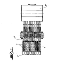
- Fig. 1 shows a top view of a pantograph unit from a plurality of arranged side by side Pantograph 1, the one not shown Conductor conductor rail are assigned.
- the Current collectors 1 is also a current collector according to the invention 1 'with connected motion sensor 2.
- Fig. 2 shows the individual pantograph according to the invention 1 'with the motion sensor 2 in a side view.
- This Current collector 1 ' has a receiving housing 3 with one of the receiving housing 3 recorded conductor line contact 4 made of an electrically conductive material.
- the receptacle 3 is springy in a conventional manner a parallelogram linkage 5 held.
- the power supply of the conductor line contact 4 takes place via the Cable 6.
- the motion sensor 2 is recorded, with which Motion sensor 2 deflections of the pantograph 1 'due of irregularities in its conductor line path can be recorded.
- the motion sensor 2 is preferred and in the exemplary embodiment as an acceleration sensor executed.
- acceleration sensor Impacts with which the pantograph 1 'acts will be determined reliably and precisely.
- the motion sensor designed as a biaxial acceleration sensor.
- Fig. 3 the two axes for one Acceleration sensor indicated by arrows.
- FIGS. 1 to 4 that the motion sensor 2 by means of an angular base 7 on the receiving housing 3 is attached.
- an electronic evaluation device not shown there 8 provided outside the pantograph 1 '.
- the motion sensor 2 is in this embodiment via a flexible ribbon cable 9 with the electronic Evaluation device 8 connected.
- the electronic Evaluation device 8 is in the embodiment Fig. 5 realized in the form of a board. On this board a flexible connecting cable 10 is connected via which connecting cable 10 the electronic evaluation device 8 with a control and / or not shown Control device is connected.
Abstract
Description
Die Erfindung betrifft einen Stromabnehmer für eine Schleifleitungsstromschiene mit zumindest einem Aufnahmegehäuse und zumindest einem von einem Aufnahmegehäuse aufgenommenen Schleifleitungskontakt aus einem elektrisch leitendem Material. - Solche Stromabnehmer werden beispielsweise in fördertechnischen Anlagen wie Elektrohängebahnen oder Elektrotragbahnen eingesetzt. In diesen Schleifleitungsanlagen müssen die Schleifleitungskontakte möglichst stets Kontakt zur Schleifleitungsstromschiene haben, damit eine funktionssichere Energieübertragung zu den mobilen Verbrauchern gewährleistet bleibt.The invention relates to a pantograph for a Conductor rail with at least one housing and at least one accommodated by a housing Contact line contact from an electrical conductive material. - Such pantographs are, for example in conveyor systems such as electric monorails or electric trams used. In these Contact line systems must have the contact line contacts if possible always contact to the conductor rail have a reliable power transmission guaranteed to mobile consumers.
Bei den aus der Praxis bekannten Stromabnehmern treten Störungen des Kontaktes zwischen Stromabnehmer und Schleifleitungsstromschiene häufig an Weichenübergängen, Stoßstellenübergängen oder aufgrund abgerissener Stromabnehmer oder aufgrund defekter Schienenverbinder auf. Bei erheblichen Störungen können längere Betriebsausfälle die Folge sein. Es ist daher wünschenswert, dass Störungen an den Schleifleitungsstromschienen bzw. im Schleifleitungsweg der Stromabnehmer rechtzeitig und vorbeugend erkannt werden, damit Abhilfe geschaffen werden kann.In the pantographs known from practice occur Faults in the contact between the pantograph and the conductor rail often at switch junctions, joint junctions or due to a broken pantograph or due to defective rail connectors. With significant Malfunctions can result in longer downtimes his. It is therefore desirable that interference with the Conductor conductor busbars or in the conductor rail route of Pantographs are recognized in a timely and preventive manner, so that remedial action can be taken.
Der Erfindung liegt das technische Problem zugrunde, einen Stromabnehmer der eingangs genannten Art anzugeben, mit dem Störungen an den Schleifleitungsstromschienen bzw. im Schleifleitungsweg des Stromabnehmers funktionssicher und effektiv rechtzeitig erkannt werden können. The invention is based on the technical problem Specify pantographs of the type mentioned, with the Faults on the conductor rail or in Current collector conductor line and reliable can be effectively recognized in time.
Zur Lösung dieses technischen Problems lehrt die Erfindung einen Stromabnehmer der eingangs genannten Art, welcher dadurch gekennzeichnet ist, dass an dem Stromabnehmer zumindest ein Bewegungssensor vorgesehen ist, mit welchem Bewegungssensor Auslenkungen des Stromabnehmers aufgrund von Unregelmäßigkeiten in seinem Schleifleitungsweg erfassbar sind.The invention teaches to solve this technical problem a pantograph of the type mentioned, which is characterized in that on the pantograph at least one motion sensor is provided with which Motion sensor deflections due to the pantograph of irregularities in its conductor line are.
Der erfindungsgemäße Stromabnehmer kann beispielsweise als Einarmschleifer, Doppelkontaktschleifer, Doppelstromabnehmer bzw. Doppel-Einarmschleifer ausgebildet sein. Der Stromabnehmer kann einen Schleifleitungskontakt aufweisen oder auch vorzugsweise zwei Schleifleitungskontakte.The pantograph according to the invention can, for example, as Single arm grinder, double contact grinder, double current collector or double-arm grinder. The The pantograph can have a contact line contact or also preferably two contact line contacts.
Der Erfindung liegt die Erkenntnis zugrunde, dass mit einem erfindungsgemäßen Bewegungssensor an dem Stromabnehmer Unregelmäßigkeiten an den Schleifleitungsstromschienen bzw. im Schleifleitungsweg funktionssicher erkannt werden können. Der Erfindung liegt weiterhin die Erkenntnis zugrunde, dass die Unregelmäßigkeiten im Schleifleitungsweg Stöße bzw. Prallschläge an dem Stromabnehmer bzw. an den Schleifleitungskontakten der Stromabnehmer erzeugen, die mit einem Bewegungssensor effektiv erfasst werden können. Solche Prallschläge entstehen beispielsweise durch Versatz an Stoßstellen, an nichtfluchtenden Übergängen der Schleifleitungsstromschiene oder durch abgerissene Stromabnehmer oder an defekten Schienenverbindern. Mit dem erfindungsgemäßen Stromabnehmer können auf einfache Weise Unregelmäßigkeiten bzw. Störungen im Schleifleitungsweg frühzeitig erkannt werden, sodass durch entsprechende Instandhaltungsoder Reparaturmaßnahmen rechtzeitig Abhilfe geschaffen werden kann.The invention is based on the finding that with a motion sensor according to the invention on the pantograph Irregularities on the conductor rail or be reliably identified in the conductor line can. The invention is also based on the knowledge based on the irregularities in the conductor rail path Impacts or impacts on the pantograph or on the Generate conductor rail contacts of pantographs that can be detected effectively with a motion sensor. Such impacts occur, for example, through misalignment at joints, at non-aligned transitions of the conductor rail or by torn pantographs or on defective rail connectors. With the invention Pantographs can easily make irregularities or faults in the conductor line early are recognized, so that by appropriate maintenance or Repair measures remedied in time can be.
Nach einer sehr bevorzugten Ausführungsform der Erfindung ist der Bewegungssensor ein zweiaxialer Beschleunigungssensor. Mit diesem Bewegungssensor können also Auslenkungen bzw. Beschleunigungen bezüglich zweier Raumachsen erfasst werden. Dieser Bewegungssensor hat sich im Rahmen der Erfindung besonders bewährt.According to a very preferred embodiment of the invention the motion sensor is a biaxial acceleration sensor. With this motion sensor, deflections can or accelerations with respect to two spatial axes become. This motion sensor has become part of the Invention particularly proven.
Es liegt im Rahmen der Erfindung, dass eine elektronische Auswertungseinrichtung vorgesehen ist, der die vom Bewegungssensor erfassten Auslenkungen in Form von Auslenkungssignalen zuführbar sind. Zweckmäßigerweise handelt es sich bei den Auslenkungssignalen um Spannungssignale, die der elektronischen Auswertungseinrichtung zugeführt werden. Es liegt dabei im Rahmen der Erfindung, dass die Spannung proportional der Auslenkung bzw. der Beschleunigung ist. Nach einer Ausführungsform kann die elektronische Auswertungseinrichtung unmittelbar am Stromabnehmer, beispielsweise am Aufnahmegehäuse befestigt sein. Nach einer anderen Ausführungsform ist dagegen die elektronische Auswertungseinrichtung außerhalb des Stromabnehmers angeordnet und der Bewegungssensor ist zweckmäßigerweise über ein flexibles Kabel an die elektronische Auswertungseinrichtung angeschlossen. Es liegt im Rahmen der Erfindung, dass die elektronische Auswertungseinrichtung digitale Signale an eine Steuer- und/oder Regeleinrichtung sendet. Die Steuer- und/oder Regeleinrichtung ist zweckmäßigerweise mit einem Mikrocomputer ausgestattet, dem die digitalen Signale zugeleitet werden. Nach sehr bevorzugter Ausführungsform der Erfindung wird bei Messung bzw. bei Erfassung eines Auslenkungsmaximums von der Steuerund/oder Regeleinrichtung ein Alarmsignal abgegeben. Dabei liegt es im Rahmen der Erfindung, dass das genannte Auslenkungsmaximum einstellbar bzw. vorgebbar ist. Wenn also der erfindungsgemäße Stromabnehmer mit Prallschlägen einer bestimmten Größenordnung beaufschlagt wird, gibt die Steuer- und/oder Regeleinrichtung ein Alarmsignal aus.It is within the scope of the invention that an electronic Evaluation device is provided, which from Motion sensor detected deflections in the form of deflection signals are feedable. Appropriately acts the deflection signals are voltage signals, the supplied to the electronic evaluation device become. It is within the scope of the invention that Voltage proportional to the deflection or acceleration is. According to one embodiment, the electronic Evaluation device directly on the pantograph, for example, be attached to the receiving housing. To another embodiment is the electronic Evaluation device arranged outside the pantograph and the motion sensor is conveniently over a flexible cable to the electronic evaluation device connected. It is within the scope of the invention that the electronic evaluation device digital Sends signals to a control and / or regulating device. The control and / or regulating device is expedient equipped with a microcomputer to which the digital signals. After very preferred Embodiment of the invention is at measurement or at Detection of a maximum deflection from the tax and / or Control device issued an alarm signal. there it is within the scope of the invention that said deflection maximum is adjustable or specifiable. So if the pantograph according to the invention with an impact certain magnitude is applied, the Control and / or regulating device an alarm signal.
Nach einer Ausführungsform der Erfindung wird der Bewegungssensor von dem Aufnahmegehäuse aufgenommen. Der Bewegungssensor kann dabei in einer taschenförmigen Aufnahme des Aufnahmegehäuses angeordnet sein. Es liegt im Rahmen der Erfindung, dass der Bewegungssensor lediglich eingesteckt wird, oder aber über eine Rastverbindung befestigt wird. - Nach einer anderen Ausführungsform der Erfindung ist der Bewegungssensor an dem Schleifleitungskontakt befestigt. Der Bewegungssensor kann beispielsweise an dem Schleifleitungskontakt angeklebt sein.According to one embodiment of the invention, the Motion sensor picked up by the receiving housing. The Motion sensor can be in a pocket-shaped receptacle of the receiving housing can be arranged. It is in the Framework of the invention that the motion sensor only is inserted, or via a snap connection is attached. - According to another embodiment of the Invention is the motion sensor on the conductor line contact attached. The motion sensor can, for example be glued to the conductor line contact.
Nachfolgend wird die Erfindung anhand einer lediglich ein Ausführungsbeispiel darstellenden Zeichnung näher erläutert. Es zeigen in schematischer Darstellung:
- Fig. 1
- eine Draufsicht auf ein Stromabnehmeraggregat aus einer Mehrzahl von Stromabnehmern,
- Fig. 2
- eine Seitenansicht eines erfindungsgemäßen Strom- abnehmers,
- Fig. 3
- den Ausschnitt A aus Fig. 2 in vergrößerter Dar- stellung,
- Fig. 4
- einen Schnitt B-B durch den Gegenstand nach Fig. 3 und
- Fig. 5
- den Gegenstand nach Fig. 2 in einer anderen Aus- führungsform.
- Fig. 1
- a plan view of a pantograph assembly from a plurality of pantographs,
- Fig. 2
- a side view of a current collector according to the invention,
- Fig. 3
- the section A from FIG. 2 in an enlarged representation,
- Fig. 4
- a section BB through the object of FIG. 3 and
- Fig. 5
- 2 in another embodiment.
Fig. 1 zeigt zunächst eine Draufsicht auf ein Stromabnehmeraggregat
aus einer Mehrzahl von nebeneinander angeordneten
Stromabnehmern 1, die einer nichtdargestellten
Schleifleitungsstromschiene zugeordnet sind. Unter den
Stromabnehmern 1 ist auch ein erfindungsgemäßer Stromabnehmer
1' mit daran angeschlossenem Bewegungssensor 2.Fig. 1 shows a top view of a pantograph unit
from a plurality of arranged side by side
Pantograph 1, the one not shown
Conductor conductor rail are assigned. Among the
Current collectors 1 is also a current collector according to the invention
1 'with connected
Fig. 2 zeigt den einzelnen erfindungsgemäßen Stromabnehmer
1' mit dem Bewegungssensor 2 in einer Seitenansicht. Dieser
Stromabnehmer 1' weist ein Aufnahmegehäuse 3 mit einem von
dem Aufnahmegehäuse 3 aufgenommenen Schleifleitungskontakt
4 aus einem elektrisch leitenden Material auf. Das Aufnahmegehäuse
3 wird in an sich üblicher Weise federnd von
einem Parallelogrammgestänge 5 gehalten. Die Stromversorgung
des Schleifleitungskontaktes 4 erfolgt über das
Kabel 6. In dem Aufnahmegehäuse 3 des Stromabnehmers 1'
wird der Bewegungssensor 2 aufgenommen, mit welchem
Bewegungssensor 2 Auslenkungen des Stromabnehmers 1' aufgrund
von Unregelmäßigkeiten in seinem Schleifleitungsweg
erfasst werden können. Der Bewegungssensor 2 ist vorzugsweise
und im Ausführungsbeispiel als Beschleunigungssensor
ausgeführt. Mit einem solchen Beschleunigungssensor können
Prallschläge, mit denen der Stromabnehmer 1' beaufschlagt
wird, funktionssicher und präzise festgestellt werden. Vorzugsweise
und im Ausführungsbeispiel ist der Bewegungssensor
als zweiaxialer Beschleunigungssensor ausgebildet.
In der Fig. 3 wurden die beiden Achsen für einen solchen
Beschleunigungssensor durch Pfeile angedeutet.Fig. 2 shows the individual pantograph according to the invention
1 'with the
Der Fig. 4 ist entnehmbar, dass der Bewegungssensor 2
mittels eines Winkelsockels 7 an dem Aufnahmegehäuse 3
befestigt ist. Im Ausführungsbeispiel nach den Fig. 1 bis 4
ist eine dort nicht näher dargestellte elektronische Auswertungseinrichtung
8 außerhalb des Stromabnehmers 1' vorgesehen.
Der Bewegungssensor 2 ist bei dieser Ausführungsform
über ein flexibles Flachbandkabel 9 mit der elektronischen
Auswertungseinrichtung 8 verbunden.4 that the
Im Ausführungsbeispiel nach Fig. 5 ist eine elektronische
Auswertungseinrichtung 8 unmittelbar an das Aufnahmegehäuse
3 des Stromabnehmers 1' angeschlossen. Die elektronische
Auswertungseinrichtung 8 ist im Ausführungsbeispiel nach
Fig. 5 in Form einer Platine verwirklicht. An diese Platine
ist ein flexibles Verbindungskabel 10 angeschlossen, über
welches Verbindungskabel 10 die elektronische Auswertungseinrichtung
8 mit einer nicht dargestellten Steuerund/oder
Regeleinrichtung verbunden ist.5 is an electronic one
Claims (5)
Applications Claiming Priority (2)
| Application Number | Priority Date | Filing Date | Title |
|---|---|---|---|
| DE20205710U DE20205710U1 (en) | 2002-04-11 | 2002-04-11 | pantograph |
| DE20205710U | 2002-04-11 |
Publications (1)
| Publication Number | Publication Date |
|---|---|
| EP1352777A1 true EP1352777A1 (en) | 2003-10-15 |
Family
ID=7969965
Family Applications (1)
| Application Number | Title | Priority Date | Filing Date |
|---|---|---|---|
| EP02027757A Withdrawn EP1352777A1 (en) | 2002-04-11 | 2002-12-11 | Current collector |
Country Status (2)
| Country | Link |
|---|---|
| EP (1) | EP1352777A1 (en) |
| DE (1) | DE20205710U1 (en) |
Cited By (7)
| Publication number | Priority date | Publication date | Assignee | Title |
|---|---|---|---|---|
| EP2165917A2 (en) * | 2008-09-22 | 2010-03-24 | Bombardier Transportation GmbH | Guidance system |
| DE202015100623U1 (en) | 2015-02-10 | 2016-05-11 | Conductix-Wampfler Gmbh | Pantograph and conductor rail system |
| DE202015100622U1 (en) | 2015-02-10 | 2016-05-11 | Conductix-Wampfler Gmbh | Pantograph and conductor rail system |
| DE102015101848A1 (en) | 2015-02-10 | 2016-08-11 | Conductix-Wampfler Gmbh | Pantograph and conductor rail system |
| DE102015101849A1 (en) | 2015-02-10 | 2016-08-11 | Conductix-Wampfler Gmbh | Pantograph and conductor rail system |
| EP3354510A1 (en) * | 2017-01-27 | 2018-08-01 | ALSTOM Transport Technologies | Method for the maintenance of a ground-level power supply device for a tram-like vehicle |
| DE102017006141A1 (en) * | 2017-06-29 | 2019-01-03 | Audi Ag | Test arrangement for a manufacturing plant and method for testing a manufacturing plant |
Families Citing this family (3)
| Publication number | Priority date | Publication date | Assignee | Title |
|---|---|---|---|---|
| DE102010007296A1 (en) | 2010-02-08 | 2011-08-11 | Paul Vahle GmbH & Co. KG, 59174 | Monitoring device for use in mobile device or vehicle for pantograph arrangement for conductor rail system, has evaluation unit, which generates signal |
| DE102018133425A1 (en) * | 2018-12-21 | 2020-06-25 | Paul Vahle Gmbh & Co. Kg | Deflection and stroke of the pantograph |
| DE102021122249A1 (en) | 2021-08-27 | 2023-03-02 | Paul Vahle Gmbh & Co. Kg | Measuring device for pantographs and method for operating the measuring device and a calibration device |
Citations (2)
| Publication number | Priority date | Publication date | Assignee | Title |
|---|---|---|---|---|
| JPH05161205A (en) * | 1991-12-06 | 1993-06-25 | Takaoka Electric Mfg Co Ltd | Pantograph |
| JP2000079839A (en) * | 1998-06-24 | 2000-03-21 | West Japan Railway Co | Impact measurement device |
-
2002
- 2002-04-11 DE DE20205710U patent/DE20205710U1/en not_active Expired - Lifetime
- 2002-12-11 EP EP02027757A patent/EP1352777A1/en not_active Withdrawn
Patent Citations (2)
| Publication number | Priority date | Publication date | Assignee | Title |
|---|---|---|---|---|
| JPH05161205A (en) * | 1991-12-06 | 1993-06-25 | Takaoka Electric Mfg Co Ltd | Pantograph |
| JP2000079839A (en) * | 1998-06-24 | 2000-03-21 | West Japan Railway Co | Impact measurement device |
Cited By (16)
| Publication number | Priority date | Publication date | Assignee | Title |
|---|---|---|---|---|
| DE102008048827A1 (en) * | 2008-09-22 | 2010-04-01 | Bombardier Transportation Gmbh | Spurführungssystem |
| EP2165917A3 (en) * | 2008-09-22 | 2011-01-19 | Bombardier Transportation GmbH | Guidance system |
| EP2165917A2 (en) * | 2008-09-22 | 2010-03-24 | Bombardier Transportation GmbH | Guidance system |
| US10525830B2 (en) | 2015-02-10 | 2020-01-07 | Conductix-Wampfler Gmbh | Current collecting device and conductor line system |
| DE202015100623U1 (en) | 2015-02-10 | 2016-05-11 | Conductix-Wampfler Gmbh | Pantograph and conductor rail system |
| DE202015100622U1 (en) | 2015-02-10 | 2016-05-11 | Conductix-Wampfler Gmbh | Pantograph and conductor rail system |
| DE102015101848A1 (en) | 2015-02-10 | 2016-08-11 | Conductix-Wampfler Gmbh | Pantograph and conductor rail system |
| DE102015101849A1 (en) | 2015-02-10 | 2016-08-11 | Conductix-Wampfler Gmbh | Pantograph and conductor rail system |
| DE102015101848B4 (en) * | 2015-02-10 | 2021-02-11 | Conductix-Wampfler Gmbh | Pantograph and conductor rail system |
| US10583742B2 (en) | 2015-02-10 | 2020-03-10 | Conductix-Wampfler Gmbh | Current collecting device and conductor line system |
| FR3062361A1 (en) * | 2017-01-27 | 2018-08-03 | Alstom Transport Technologies | METHOD FOR MAINTAINING A GROUND FEEDING DEVICE FOR A TRAMWAY VEHICLE |
| US10683022B2 (en) | 2017-01-27 | 2020-06-16 | Alstom Transport Technologies | Method for the maintenance of a ground-level power supply device for a tram-like vehicle |
| EP3354510A1 (en) * | 2017-01-27 | 2018-08-01 | ALSTOM Transport Technologies | Method for the maintenance of a ground-level power supply device for a tram-like vehicle |
| AU2018200512B2 (en) * | 2017-01-27 | 2022-06-02 | Alstom Transport Technologies | Method for the maintenance of a ground-level power supply device for a tram-like vehicle |
| DE102017006141A1 (en) * | 2017-06-29 | 2019-01-03 | Audi Ag | Test arrangement for a manufacturing plant and method for testing a manufacturing plant |
| DE102017006141B4 (en) | 2017-06-29 | 2021-09-23 | Audi Ag | Test arrangement for a production plant and method for testing a production plant |
Also Published As
| Publication number | Publication date |
|---|---|
| DE20205710U1 (en) | 2002-08-14 |
Similar Documents
| Publication | Publication Date | Title |
|---|---|---|
| DE10065392B4 (en) | Test drive unit for electrical equipment in a vehicle | |
| EP1352777A1 (en) | Current collector | |
| WO2008135183A1 (en) | Device for checking the attachment of a circuit board on a carrier | |
| DE10248012A1 (en) | Battery connection structure for motor vehicles, has connection structure which respectively covers upper and lower surface of bus bars, so as to prevent short circuit between bus bars | |
| DE19529070A1 (en) | Pantograph | |
| DE102018123609B3 (en) | Temperature measuring device, connector, manufacturing process and temperature measuring process | |
| EP2737327B1 (en) | Circuit for conducting an electrical current | |
| EP2085785A2 (en) | Device for measuring electricity | |
| DE3937881C2 (en) | ||
| DE2915653C2 (en) | Concrete sleeper for a track system | |
| DE4438720A1 (en) | Arrangement for detecting discontinuities in electrical power rail for railway vehicles | |
| EP0035700A1 (en) | Digital electronic angle measurement device | |
| WO1997043802A1 (en) | Contacting device | |
| EP0076292A1 (en) | Electric contact, particularly for printed circuits of small electric appliances. | |
| DE102007017730A1 (en) | Sensor device, has busbars connecting supply voltage inputs of respective sensors in electrically conductive manner for contacting with plug, where sensors are rotatably arranged against each other around specific degrees | |
| DE102012012025A1 (en) | Bridge device for electrical device, has primary and secondary electrical leading bridges that are made up of different conductive materials | |
| EP0078481B1 (en) | Contacting device with a clamping element for contacting electrical contact spots on circuit boards | |
| DE2919836C2 (en) | ||
| DE3120188C1 (en) | Device for power supply and, if necessary, connection of travel and control power rails of monorail and monorail overhead conveyors | |
| DE3443081C2 (en) | ||
| EP3883808B1 (en) | Current collector and contact line system | |
| DE3009236C2 (en) | Arrangement with contact sockets for electrical connections | |
| DE10192143B4 (en) | Holding and contacting device for sliding contacts | |
| DE320150C (en) | Tab connection with contact tips | |
| DE851764C (en) | Device for connecting parts of the track of a toy and model train to a power source |
Legal Events
| Date | Code | Title | Description |
|---|---|---|---|
| PUAI | Public reference made under article 153(3) epc to a published international application that has entered the european phase |
Free format text: ORIGINAL CODE: 0009012 |
|
| AK | Designated contracting states |
Kind code of ref document: A1 Designated state(s): AT BE BG CH CY CZ DE DK EE ES FI FR GB GR IE IT LI LU MC NL PT SE SI SK TR |
|
| AX | Request for extension of the european patent |
Extension state: AL LT LV MK RO |
|
| 17P | Request for examination filed |
Effective date: 20040407 |
|
| AKX | Designation fees paid |
Designated state(s): BE DE FR GB IT |
|
| RAP1 | Party data changed (applicant data changed or rights of an application transferred) |
Owner name: PAUL VAHLE GMBH & CO. KG |
|
| 17Q | First examination report despatched |
Effective date: 20091014 |
|
| STAA | Information on the status of an ep patent application or granted ep patent |
Free format text: STATUS: THE APPLICATION IS DEEMED TO BE WITHDRAWN |
|
| 18D | Application deemed to be withdrawn |
Effective date: 20100225 |