EP1351555A2 - Einrichtung zur Zustandserfassung an einer Platte oder Wand eines Haushaltsgerätes - Google Patents
Einrichtung zur Zustandserfassung an einer Platte oder Wand eines Haushaltsgerätes Download PDFInfo
- Publication number
- EP1351555A2 EP1351555A2 EP03007210A EP03007210A EP1351555A2 EP 1351555 A2 EP1351555 A2 EP 1351555A2 EP 03007210 A EP03007210 A EP 03007210A EP 03007210 A EP03007210 A EP 03007210A EP 1351555 A2 EP1351555 A2 EP 1351555A2
- Authority
- EP
- European Patent Office
- Prior art keywords
- sound wave
- wall
- plate
- temperature
- sound
- Prior art date
- Legal status (The legal status is an assumption and is not a legal conclusion. Google has not performed a legal analysis and makes no representation as to the accuracy of the status listed.)
- Withdrawn
Links
Images

Classifications
-
- H—ELECTRICITY
- H05—ELECTRIC TECHNIQUES NOT OTHERWISE PROVIDED FOR
- H05B—ELECTRIC HEATING; ELECTRIC LIGHT SOURCES NOT OTHERWISE PROVIDED FOR; CIRCUIT ARRANGEMENTS FOR ELECTRIC LIGHT SOURCES, IN GENERAL
- H05B3/00—Ohmic-resistance heating
- H05B3/68—Heating arrangements specially adapted for cooking plates or analogous hot-plates
- H05B3/74—Non-metallic plates, e.g. vitroceramic, ceramic or glassceramic hobs, also including power or control circuits
- H05B3/746—Protection, e.g. overheat cutoff, hot plate indicator
-
- H—ELECTRICITY
- H05—ELECTRIC TECHNIQUES NOT OTHERWISE PROVIDED FOR
- H05B—ELECTRIC HEATING; ELECTRIC LIGHT SOURCES NOT OTHERWISE PROVIDED FOR; CIRCUIT ARRANGEMENTS FOR ELECTRIC LIGHT SOURCES, IN GENERAL
- H05B2213/00—Aspects relating both to resistive heating and to induction heating, covered by H05B3/00 and H05B6/00
- H05B2213/07—Heating plates with temperature control means
Definitions
- the invention relates to a device for condition detection on a Plate or a wall of a household appliance, in particular Kitchen appliance, especially kitchen stoves.
- the object of the invention is a device for temperature detection to propose the type mentioned at the outset with which the Temperature detection is simplified and improved.
- the above object is characterized by the features of characterizing part of claim 1 solved.
- This Changes can be made by measuring the transit time of preferably pulsed signals, the phase shift, the amplitude change or a resonance detuning.
- the detectable state is in particular the temperature and / or exposure to the plate or wall, for example dirt, overflowed Cookware, a break or a finger touch on the plate or wall.
- the decor is simple on the plate or wall mountable.
- the area whose condition is to be recorded is on easy to narrow down.
- the setup can be done with simple Components can be realized.
- the sound waves can be Rayleigh waves or Lamb waves. This the two types of sound waves differ in their spatial distribution structure. Rayleigh waves plant on the Surface continues. Vibrations of the thickness of the Lamb waves occur Plate or wall on.
- Temperature detection has the advantage of temperature detection very close to the bottom of the saucepan that the device is installed Hotplate not affected, no special pots are necessary and there is no shading of the cooking zone.
- the device can be used for heating elements and / or Control the display elements of the device, especially kitchen stoves.
- the evaluation circuit preferably detects the temperature-dependent changing phase shift or phase position of the sound waves.
- the tuning is detuned depending on the temperature.
- the evaluation circuit adjusts the sound wave frequency so that the Resonance state is maintained.
- the necessary measure of Frequency change corresponds to the respective temperature change.
- the evaluation circuit can also change the amplitude of the Record sound waves. This means additional operating states recognizable.
- each other spaced first and second places there is between each other spaced first and second places a measuring section.
- a measuring section there is between each other spaced first and second places a measuring section.
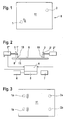
- Two options are provided for each measuring section. In one case (see Fig.1, Fig.2, Fig.3, Fig.5, Fig.6, Fig.7) is in the first position Sound wave transmitter 1 and in the second place Sound wave receiver 2 arranged. Both can use piezo elements 1 ', 2' work as transmitting or receiving elements.
- the A transmission circuit 1 ′′ is assigned to sound wave transmitter 1 Sound wave transmitter 2 is assigned a receiving circuit 2 ".
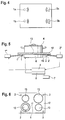
- a sound wave reflective element 3 arranged in the other case (see Fig. 4, Fig. 8) is one of Transmitting mode can be switched over to receiving mode intermittently Sound wave transmitter 1 and in the second place a sound wave reflective element 3 arranged.
- the sound wave reflecting Element 3 can be applied to the plate or wall by a in particular, printed, stripes exist, which is such a defect forms that impinging sound waves are reflected.
- Such Defined defect can also be formed or molded the plate or wall. Such a defect also forms possible breakage of the plate.
- the working frequency of the sound wave transmitter 1 is, for example about 1 MHz.
- the sound waves of the sound wave transmitter 1 plant in or on the Slab or wall away. Depending on the temperature of the plate or wall - and the length of the measuring section - the phase position of the changes Sound waves.
- Evaluation circuit 4 which the phase position of the transmitted Sound waves compared with the phase position of the received sound waves and evaluates the resulting difference.
- the phase difference forms a measure of the respective temperature or Temperature change.
- it can also be provided that to tune the system to resonance and at a temperature-related detuning of the resonance Readjust the sound wave frequency to the resonance state.
- the size the frequency change required is a measure of the Temperature change.
- a control circuit 5 is assigned to the evaluation circuit 4 controls heating elements 6 and / or display elements 7 of the device (cf. Fig.2, Fig.5).
- the sound wave transmitter 1 is in one underlying corner area of an oven wall 8 and the Sound wave receiver 2 diagonally opposite in an overhead Area of the oven wall 8 arranged. Both are different Outside 9 attached.
- the piezo elements 1 ', 2' of the Sound wave transmitter 1 and sound wave receiver 2 not directly on the Fixed oven wall 8, but with this over spacers 10 connected.
- the piezo elements are glued to the spacers 10.
- the spacers 10 are connected to the oven wall 8.
- the spacers 10 consist of a bad heat-conducting, but reverberant material, for example ceramic.
- the Spacers 10 are used to control the temperature at the piezo elements to reduce far that their maximum permissible operating temperature is not exceeded.
- the inside 11 of the oven wall 8 limits the baking space.
- the measuring section extends diagonally over the oven wall 8. This means that the temperature in a large area of the oven wall 8 and not only on one Single point is recorded. The temperature recorded in this way forms a safe one Measure of the temperature actually prevailing in the interior of the oven. If necessary, the temperature detection can be described in the Way on several walls, including the bottom wall and the Ceiling wall take place, with the transmitter 1 on one wall and on one other wall of the receiver 2 can be arranged.
- FIG. 3 there is an upper one on the oven wall 8 Measuring section with a sound wave transmitter 1a and a Sound wave receiver 2a and a lower measuring section with a Sound wave transmitter 1b and a sound wave receiver 2b provided.
- the upper measuring section records the top heat in the oven.
- the lower measuring section records the bottom heat in the oven.
- the distribution of Top heat and bottom heat can be varied during the baking process.
- the embodiment according to FIG. 4 corresponds to the detection of the Top heat and the bottom heat of the embodiment according to Figure 3.
- sound waves are reflective elements 3a, 3b arranged on the inside of the oven wall 8.
- the sound wave transmitter 1a, 1b are intermittent via the transmitter circuit from Transmission mode switched to reception mode.
- the Sound wave reflecting element 3 can also from the edge of the Oven wall 8 can be formed itself.
- the measuring section can also be in two or more walls of the Oven run. Then one of the walls is the Sound wave transmitter 1 and on another oven wall 8 Sound wave receiver 2 or the sound wave reflecting element 3 arranged.
- Figures 5 to 8 show the device with a glass ceramic plate 12 of a kitchen stove, which has several cooking zones 13.
- everybody Cooking zone 13 is at least one heating element 6 for a cookware K assigned.
- the sound wave transmitter 1 and diagonally opposite the cooking zone 13 is the Sound wave receiver 2 (see Fig. 5, Fig. 6, Fig. 7) or a sound wave reflective element 3 or more sound waves reflective Elements 3 (see Fig. 8) arranged.
- the temperature of the respective cooking zone 13 and thus the temperature of the cookware K is detected.
- the changes according to the temperature of the cooking zone 13 Phase position of the received sound waves. As described, the Phase position compared, including the above Resonance tuning and frequency adjustment via the Evaluation circuit 4 and the transmitter circuit can be done.
- the Electric heating element 6 is used by the control circuit 5 accordingly the determined temperature controlled.
- a single sound wave transmitter 1 is provided. This related to each of the four cooking zones 13 are opposite in corner areas the glass ceramic plate 12 arranged sound wave receiver 2.
- the Sound wave transmitter 1 and the sound wave receiver 2 are on the Bottom 15 of the glass ceramic plate 12 arranged (see Fig. 5).
- FIG. 7 is similar to that according to FIG. 6, but only with two cooking zones 13 sound wave receivers 2 are provided.
- each sound wave transmitter 1 is each switchable from transmit mode to receive mode in the Corner areas of the glass ceramic plate 12 next to the cooking zones 13 arranged.
- sound waves reflecting elements 3 on the Bottom 15 of the glass ceramic plate 12 is provided, each of the four sound wave transmitters 1 outgoing sound waves back to this reflect.
- the sound wave reflecting elements 3 can by strips printed on the top of the glass ceramic plate 12 be educated. It can reflect the sound waves of the four Sound wave transmitter 1 back to the respective sound wave transmitter 1 only suitably shaped element reflecting sound waves 3 suffice.
- the sound wave reflecting element 3 or Elements 3 reflecting sound waves can be made of a hard Ceramics consist of an impurity reflecting the sound waves at the Forms top of the glass ceramic plate 12.
- the amplitude compare the transmitted and received sound waves it is also possible to change the amplitude compare the transmitted and received sound waves.
- the amplitude of the sound waves is damped, for example by overflowed cookware or by touching a switching zone. Events or states can be compared with the amplitude evaluate on the hotplate 12 and to control functions of the Device.
- the evaluation circuit 4 To determine the presence or absence of a cookware can the evaluation circuit 4 the rate of increase Cooking zone temperature in relation to that on the appliance for a cooking zone 13 Determine the heating power set. The slew rate, the Temperature gradient is larger when there is no cookware on the Cooking zone 13 stands as if there were cookware on the cooking zone 13 stands.
- the evaluation circuit 4 or the control circuit 5 By implementing an appropriate algorithm in the evaluation circuit 4 or the control circuit 5, which in practice are formed by a microprocessor or microcontroller, it is possible to switch off or reduce the heating output if none Cookware is on the cooking zone 13. It becomes a dangerous one Operating state avoided.
- the device By measuring the temperature rise during manufacture or The device is put into operation for the first time when it is fully energized Heating elements 14 for each cooking zone 13 - without cookware - the Temperature rise determined. Then turns on in the cooking mode Put cookware with food on the cooking zone 13, then the Characteristic curve of the temperature curve flatter than in the initial measurement or the value saved from it. Depending on this The difference may be the required heat-up temperature or the Parboiling power can be controlled.
- the device can be "trembling” via the evaluation circuit 4 Evaluate (trembling) the sound signal amplitude. This effect occurs, briefly before the food comes to a boil. He is familiar with the Noise connected. This creates in the cookware Sound waves that overlap the sound waves of the plate or wall. This phenomenon can be determined by evaluating the amplitude or Frequency of the "trembling" of the received sound signal can be detected.
- the parboiling process can be designed as follows:
- the parboil time will end at the latest when one of the respective Continuous cooking level has been assigned to the specific cooking time.
- the Cooking time is ended prematurely when the by the Temperature rise gradients determined a shorter period of time pretends.
- the boil-up period is ended prematurely even when that is over the "trembling" signal determined before the other criteria occurs.
- the device described also makes it possible to remove the residual heat the cooking zone 13 to be taken into account.
- the temperature measurement of the Cooking zone 13 on the phase shift allows at Entry of a new setting variable by the user, which is still energy to be supplied taking into account the range of To control cooking zone 13 still existing heat content. It can also the heating time by an amount dependent on the residual heat can be reduced.
- the device described is also suitable for recognizing a Overflow of cookware from the cookware onto the cooking zone 13. If cookware overflows, the sound signal is damped in such a way that the sound signal amplitude is reduced. Thereupon is then over the Evaluation circuit 4 and the control circuit 5 on the heating power reset or switched off an uncritical value. It can it should be provided that when the cooking zone 13 is done, the heating element 14 with the previous heating power or a reduced heating power is switched on again by the Continue cooking.
- the device described can also be a state of the art the technology of conventional electromechanical temperature limiters there is no need to protect the glass ceramic plate 12 from overheating.
- the Evaluation circuit 4 with control circuit 5 is programmed for this purpose, that before the critical glass ceramic temperature is reached Heating power is reduced or switched off.
- the described device also enables the following safety function: Fires always occur when operating kitchen stoves because fat in the cookware overheats and ignites itself.
- the flash point of cooking oils and fats is around 280 ° C.
- the self-ignition of cooking oils and cooking fats occurs at around 370 ° C.
- the temperature of the cooking zone 13 can be limited to a value below the autoignition temperature of cooking oils and cooking fats. If the limit value is exceeded for a certain time, the heating output is switched off or at least reduced.
- the device described is also suitable as a warning indicator for hot Cooking zones 13. It determines the warning signal from the phase shift the sound waves.
- the Evaluation circuit 4 and the control circuit 5 are programmable in such a way that either the cooking zone affected by the break or all Cooking zones can be switched off.
Landscapes
- Chemical & Material Sciences (AREA)
- Engineering & Computer Science (AREA)
- Ceramic Engineering (AREA)
- Electric Stoves And Ranges (AREA)
- Air Conditioning Control Device (AREA)
Abstract
Description
Beim Betrieb von Küchenherden entstehen immer wieder Brände, weil sich Fett im Kochgeschirr überhitzt und selbst entzündet. Der Flammpunkt von Speiseölen und Speisefetten liegt bei ca. 280°C. Die Selbstentzündung von Speiseölen und Speisefetten erfolgt bei etwa 370°C. Bei der beschriebenen Einrichtung kann die Temperatur der Kochzone 13 auf einen Wert unterhalb der Selbstentzündungstemperatur von Speiseölen und Speisefetten begrenzt werden. Wird der Begrenzungswert für eine gewisse Zeit überschritten, dann wird die Heizleistung abgeschaltet oder wenigstens reduziert.
Claims (12)
- Einrichtung zur Zustandserfassung an einer Platte oder einer Wand eines Haushaltgerätes, insbesondere Küchengerätes, speziell Küchenherdes,
dadurch gekennzeichnet, dass an wenigstens einer ersten Stelle der Platte (12) oder der Wand (8) ein Schallwellensender (1) Schallwellen auf die Platte (12) oder die Wand (8) überträgt und dass an einer vom Schallwellensender (1) entfernten zweiten Stelle der Platte (12) oder der Wand (8) ein Schallwellenempfänger (2) oder ein Schallwellen reflektierendes Element (3) angeordnet ist, wobei wenigstens ein Parameter der Schallwellen durch einen auf dem Übertragungsweg der Schallwellen zwischen der ersten Stelle und der zweiten Stelle herrschenden Zustand beeinflusst wird, und dass eine Auswerteschaltung (4) die zustandsbedingte Beeinflussung des Parameters der Schallwellen zur Auslösung eines Steuervorgangs und/oder einer Anzeige auswertet. - Einrichtung nach Anspruch 1,
dadurch gekennzeichnet, dass der Zustand die Temperatur oder eine Beaufschlagung der Oberfläche der Platte (12) oder Wand (8) ist oder der Parameter die Laufzeit oder die Phasenlage, die Resonanzverstimmung oder die Amplitude der, insbesondere gepulsten, Schallwellensignale ist. - Einrichtung nach einem der vorhergehenden Ansprüche,
dadurch gekennzeichnet, dass die Auswerteschaltung (4) wenigstens ein Heizelement (6) und/oder wenigstens ein Anzeigeelement (7) des Haushaltgeräts steuert. - Einrichtung nach einem der vorhergehenden Ansprüche,
dadurch gekennzeichnet, dass die Schallwellen auf Resonanz abgestimmt sind, wobei sich die Abstimmung zustandsabhängig, insbesondere temperaturabhängig, verstimmt, und dass die Auswerteschaltung (4) die Schallwellenfrequenz so nachregelt, dass der Resonanzzustand erhalten bleibt, wobei die Größe der Frequenznachregelung als Maß für den herrschenden Zustand, insbesondere die Temperatur, ausgewertet wird. - Einrichtung nach einem der vorhergehenden Ansprüche,
dadurch gekennzeichnet, dass der Schallwellensender (1) intermittierend von Sendebetrieb auf Empfangsbetrieb umschaltbar ist, wobei er im Empfangsbetrieb das von dem Schallwellen reflektierenden Element (3) kommende Schallwellensignal erfasst. - Einrichtung nach einem der vorhergehenden Ansprüche,
dadurch gekennzeichnet, dass, wenn ein oder mehrere Schallwellensender (1) und Schallwellenempfänger (2) oder Schallwellen reflektierende Elemente (3) an der Platte (12) oder Wand (8) vorgesehen sind, das Schallwellensignal zur Erkennung der unterschiedlichen Schallwellenstrecken moduliert ist. - Einrichtung nach einem der vorhergehenden Ansprüche,
dadurch gekennzeichnet, dass die Wand eine Backofenwand (8) ist und der Schallwellensender (1) sowie der Schallwellenempfänger (2) außen bzw. das Schallwellen reflektierende Element (3) innen an der Backofenwand (8) angeordnet ist,
wobei vorzugsweise der Schallwellensender (1) und der Schallwellenempfänger (2) oder das Schallwellen reflektierende Element (3) in unterschiedlichen Höhen der Backofenwand (8) angeordnet sind. - Einrichtung nach Anspruch 7,
dadurch gekennzeichnet, dass zur separaten Erfassung der im Backofen herrschenden Oberhitze und Unterhitze oben und unten an der Backofenwand (8) je ein Schallwellensender (1,1') und ein Schallwellenempfänger (2,2') oder ein Schallwellen reflektierendes Element (3,3') angeordnet ist. - Einrichtung nach einem der vorhergehenden Ansprüche 1 bis 6,
dadurch gekennzeichnet, dass die Platte eine Kochplatte (12), insbesondere Glaskeramikplatte, mit mehreren Kochzonen (13) ist und dass der oder die Schallwellensender (1) und der oder die Schallwellenempfänger (2) unten bzw. das Schallwellen reflektierende Element (3) oder die Schallwellen reflektierenden Elemente oben an der Kochplatte (12) angeordnet sind,
wobei vorzugsweise in der Mitte zwischen mehreren Kochzonen (13) ein Schallwellensender (1) und in einem oder mehreren der Eckbereiche der Kochplatte (12) Schallwellenempfänger (2) oder Schallwellen reflektierende Elemente (3) angeordnet sind und zwischen dem gemeinsamen Schallwellensender (1) und je einem der Schallwellenempfänger (2) oder Schallwellen reflektierenden Elemente (3) je eine Kochzone (13) liegt
oder in zwei oder mehreren Eckbereichen der Kochplatte (12) je ein Schallwellensender (1) angeordnet ist und in der Mitte zwischen den Kochzonen (13) ein oder mehrere Schallwellenempfänger (2) oder Schallwellen reflektierende Elemente (3) angeordnet sind. - Einrichtung nach einem der vorhergehenden Ansprüche,
dadurch gekennzeichnet, dass die Auswerteschaltung (4) die Anstiegsgeschwindigkeit der Temperatur der Kochzone (13) derart auswertet, dass die Anwesenheit oder Abwesenheit eines Kochgeschirrs und/oder das Leerkochen des Kochgeschirrs erfasst wird und/oder ein Ankochen und/oder Fortkochen gesteuert wird,
und/oder dass die Auswerteschaltung (4) die Temperatur der Kochzone (13) derart auswertet, dass die Wärme erfasst wird und/oder eine Temperaturbegrenzungsfunktion und/oder eine Sicherheitstemperaturbegrenzung erreicht wird und/oder eine Warnanzeige bei heisser Kochzone (13) ausgelöst wird. - Einrichtung nach einem der vorhergehenden Ansprüche,
dadurch gekennzeichnet, dass der Schallwellensender (1) und/oder der Schallwellenempfänger (2) ein Piezoelement aufweist
und/oder dass das Schallwellen reflektierende Element (3) von einer auf die Platte (12) oder Wand (8) aufgebrachten, insbesondere aufgedruckten Schicht oder einer Einformung oder Ausformung, besteht. - Einrichtung nach einem der vorhergehenden Ansprüche,
dadurch gekennzeichnet, dass die Auswerteschaltung (4) einen in einem Kochgeschirr beginnenden Siedevorgang auswertet
und/oder dass die Auswerteschaltung (4) einen Überlauf von Kochgut auf die Platte (12) auswertet
und/oder dass die Auswerteschaltung (4) einen Bruch der Platte (12) auswertet.
Applications Claiming Priority (2)
| Application Number | Priority Date | Filing Date | Title |
|---|---|---|---|
| DE10215043 | 2002-04-05 | ||
| DE10215043A DE10215043A1 (de) | 2002-04-05 | 2002-04-05 | Einrichtung zur Zustandserfassung an einer Platte oder Wand eines Haushaltsgerätes |
Publications (2)
| Publication Number | Publication Date |
|---|---|
| EP1351555A2 true EP1351555A2 (de) | 2003-10-08 |
| EP1351555A3 EP1351555A3 (de) | 2007-09-19 |
Family
ID=27816160
Family Applications (1)
| Application Number | Title | Priority Date | Filing Date |
|---|---|---|---|
| EP03007210A Withdrawn EP1351555A3 (de) | 2002-04-05 | 2003-03-29 | Einrichtung zur Zustandserfassung an einer Platte oder Wand eines Haushaltsgerätes |
Country Status (4)
| Country | Link |
|---|---|
| US (1) | US20030222076A1 (de) |
| EP (1) | EP1351555A3 (de) |
| DE (1) | DE10215043A1 (de) |
| PL (1) | PL359406A1 (de) |
Cited By (2)
| Publication number | Priority date | Publication date | Assignee | Title |
|---|---|---|---|---|
| EP2801884A3 (de) * | 2013-05-08 | 2015-04-22 | V-Zug AG | Automatische Regelung von Kochprozessen |
| EP2772692A3 (de) * | 2013-03-01 | 2015-11-18 | BSH Hausgeräte GmbH | Kochfeldvorrichtung |
Families Citing this family (5)
| Publication number | Priority date | Publication date | Assignee | Title |
|---|---|---|---|---|
| DE102004008739A1 (de) * | 2004-02-23 | 2005-09-08 | BSH Bosch und Siemens Hausgeräte GmbH | Sensoreinrichtung für ein Haushaltsgerät |
| DE102016114822B3 (de) * | 2016-08-10 | 2017-10-12 | Miele & Cie. Kg | Kochfeld, insbesondere Induktionskochfeld |
| CN107889300A (zh) * | 2016-09-29 | 2018-04-06 | 浙江久康电器有限公司 | 插接式红外线电热炉盘及装用该电热炉盘的电加热灶 |
| EP3402310B1 (de) * | 2017-05-08 | 2020-01-08 | Vestel Elektronik Sanayi ve Ticaret A.S. | Detektionssystem eines trockenen zustands eines topfes |
| DE102019123703A1 (de) * | 2019-09-04 | 2021-03-04 | Miele & Cie. Kg | Kochfeld mit mindestens einem Temperatursensor |
Family Cites Families (10)
| Publication number | Priority date | Publication date | Assignee | Title |
|---|---|---|---|---|
| JPS5950320A (ja) * | 1982-09-16 | 1984-03-23 | Matsushita Electric Ind Co Ltd | 調理器 |
| EP0251008A1 (de) * | 1986-07-03 | 1988-01-07 | Siemens Aktiengesellschaft | Anordnung zur Bestimmung der Lage eines bewegbaren Körpers mit Ultraschall |
| DE3934157C2 (de) * | 1989-10-12 | 1999-01-28 | Bosch Siemens Hausgeraete | Kochmulde |
| US5175709A (en) * | 1990-05-22 | 1992-12-29 | Acoustic Imaging Technologies Corporation | Ultrasonic transducer with reduced acoustic cross coupling |
| DE19514307A1 (de) * | 1994-05-19 | 1995-11-23 | Siemens Ag | Duplexer für ein Ultraschallabbildungssystem |
| DE19723127A1 (de) * | 1997-06-03 | 1998-12-10 | Ako Werke Gmbh & Co | Einrichtung zur drahtlosen Ermittlung der Temperatur und einer Kennung eines Kochgeschirrs an einen Kochherd |
| JP3745535B2 (ja) * | 1998-06-10 | 2006-02-15 | 富士工業株式会社 | 超音波計測方法及び装置 |
| DE19851884A1 (de) * | 1998-11-11 | 2000-05-18 | Diehl Stiftung & Co | Ultraschall-Sensor für eine Dunstabzugshaube |
| US6188047B1 (en) * | 1999-11-15 | 2001-02-13 | Minpat Co. | Radiant electric heater |
| US6583392B2 (en) * | 2000-12-22 | 2003-06-24 | General Electric Company | Apparatus and method for determining properties of a cooktop using ultrasound techniques |
-
2002
- 2002-04-05 DE DE10215043A patent/DE10215043A1/de not_active Ceased
-
2003
- 2003-03-28 PL PL03359406A patent/PL359406A1/xx not_active Application Discontinuation
- 2003-03-29 EP EP03007210A patent/EP1351555A3/de not_active Withdrawn
- 2003-04-07 US US10/408,808 patent/US20030222076A1/en not_active Abandoned
Cited By (2)
| Publication number | Priority date | Publication date | Assignee | Title |
|---|---|---|---|---|
| EP2772692A3 (de) * | 2013-03-01 | 2015-11-18 | BSH Hausgeräte GmbH | Kochfeldvorrichtung |
| EP2801884A3 (de) * | 2013-05-08 | 2015-04-22 | V-Zug AG | Automatische Regelung von Kochprozessen |
Also Published As
| Publication number | Publication date |
|---|---|
| EP1351555A3 (de) | 2007-09-19 |
| PL359406A1 (en) | 2003-10-06 |
| US20030222076A1 (en) | 2003-12-04 |
| DE10215043A1 (de) | 2003-10-23 |
Similar Documents
| Publication | Publication Date | Title |
|---|---|---|
| EP2510413B1 (de) | Verfahren zur steuerung eines kochprozesses | |
| DE102011081355A1 (de) | Einrichten einer Überwachungsvorrichtung für ein Kochfeld | |
| EP1391141B1 (de) | Verfahren und vorrichtung zur begrenzung und/oder steuerung der oberflächentemperatur eines kochfelds | |
| EP0780081B1 (de) | Verfahren zur automatischen Regelung von beheizbaren Kochstellen | |
| EP1351555A2 (de) | Einrichtung zur Zustandserfassung an einer Platte oder Wand eines Haushaltsgerätes | |
| DE102009020628A1 (de) | Kochfeld und Verfahren zum Erhitzen von auf dem Kochfeld aufgestellten Kochgefäßen | |
| DE3117205A1 (de) | Optoelektronische kochfeldsteuerung | |
| CH708042A2 (de) | Automatische Regelung von Kochprozessen. | |
| DE3934157A1 (de) | Kochmulde fuer einen elektroherd oder dgl. | |
| DE4413979C2 (de) | Sensorgesteuerte Garungseinheit und Gargerät | |
| DE102016114822B3 (de) | Kochfeld, insbesondere Induktionskochfeld | |
| DE102004059822A1 (de) | Sensorvorrichtung für ein Kochfeld, Verfahren zum Betrieb einer Sensorvorrichtung und Verwendung eines Temperatursensors als Topferkennungssensor | |
| WO2015018891A1 (de) | Kocheinrichtung und verfahren zum betreiben der kocheinrichtung | |
| DE102019132478A1 (de) | Verfahren zur automatischen Zuordnung mindestens eines Tauchsiedergeräts zu mindestens einer Kochstelle eines induktiven Kochfelds, induktives Kochfeld, Tauchsiedergerät und System zur Durchführung des Verfahrens | |
| EP3282816B1 (de) | Induktives kochsystem | |
| EP2983449B1 (de) | Verfahren zum beschleunigen eines kochvorgangs, steuereinrichtung sowie gargerät hierfür | |
| EP3031296B1 (de) | Kocheinrichtung und verfahren zum betreiben der kocheinrichtung | |
| EP3031298A1 (de) | Kocheinrichtung und verfahren zum betreiben einer kocheinrichtung | |
| EP1783434B1 (de) | Anordnung eines Elektrogerätes in einem Einbaumöbel sowie Steuerverfahren dafür | |
| DE102005040041B3 (de) | Glaskeramikkochfeld mit wenigstens einem Kochfeldbereich | |
| WO2015018890A1 (de) | Kocheinrichtung und verfahren zum betreiben der kocheinrichtung | |
| EP3031297B1 (de) | Kocheinrichtung und verfahren zum betreiben der kocheinrichtung | |
| EP4387393B1 (de) | Verfahren zum betrieb eines induktiven kochsystems | |
| DE19734960A1 (de) | Kochzone | |
| DE102022129549A1 (de) | Sensorgesteuertes Kochfeld |
Legal Events
| Date | Code | Title | Description |
|---|---|---|---|
| PUAI | Public reference made under article 153(3) epc to a published international application that has entered the european phase |
Free format text: ORIGINAL CODE: 0009012 |
|
| AK | Designated contracting states |
Kind code of ref document: A2 Designated state(s): AT BE BG CH CY CZ DE DK EE ES FI FR GB GR HU IE IT LI LU MC NL PT RO SE SI SK TR |
|
| AX | Request for extension of the european patent |
Extension state: AL LT LV MK |
|
| PUAL | Search report despatched |
Free format text: ORIGINAL CODE: 0009013 |
|
| AK | Designated contracting states |
Kind code of ref document: A3 Designated state(s): AT BE BG CH CY CZ DE DK EE ES FI FR GB GR HU IE IT LI LU MC NL PT RO SE SI SK TR |
|
| AX | Request for extension of the european patent |
Extension state: AL LT LV MK |
|
| STAA | Information on the status of an ep patent application or granted ep patent |
Free format text: STATUS: THE APPLICATION IS DEEMED TO BE WITHDRAWN |
|
| 18D | Application deemed to be withdrawn |
Effective date: 20071001 |