EP1350996B1 - Gleitelement - Google Patents
Gleitelement Download PDFInfo
- Publication number
- EP1350996B1 EP1350996B1 EP03252108A EP03252108A EP1350996B1 EP 1350996 B1 EP1350996 B1 EP 1350996B1 EP 03252108 A EP03252108 A EP 03252108A EP 03252108 A EP03252108 A EP 03252108A EP 1350996 B1 EP1350996 B1 EP 1350996B1
- Authority
- EP
- European Patent Office
- Prior art keywords
- sliding
- dimples
- sliding face
- dimple
- sliding element
- Prior art date
- Legal status (The legal status is an assumption and is not a legal conclusion. Google has not performed a legal analysis and makes no representation as to the accuracy of the status listed.)
- Expired - Lifetime
Links
- 239000012530 fluid Substances 0.000 claims description 106
- 238000000034 method Methods 0.000 claims description 92
- 238000003491 array Methods 0.000 claims description 11
- 239000000314 lubricant Substances 0.000 description 22
- 230000007423 decrease Effects 0.000 description 17
- 238000012360 testing method Methods 0.000 description 15
- 239000000463 material Substances 0.000 description 12
- HBMJWWWQQXIZIP-UHFFFAOYSA-N silicon carbide Chemical compound [Si+]#[C-] HBMJWWWQQXIZIP-UHFFFAOYSA-N 0.000 description 12
- 239000003921 oil Substances 0.000 description 11
- 229910010271 silicon carbide Inorganic materials 0.000 description 11
- 238000007789 sealing Methods 0.000 description 10
- 230000000694 effects Effects 0.000 description 9
- 238000005488 sandblasting Methods 0.000 description 8
- 238000005299 abrasion Methods 0.000 description 7
- 239000011148 porous material Substances 0.000 description 6
- 230000003247 decreasing effect Effects 0.000 description 5
- 230000033001 locomotion Effects 0.000 description 5
- 238000010276 construction Methods 0.000 description 4
- 238000005461 lubrication Methods 0.000 description 4
- 230000020169 heat generation Effects 0.000 description 3
- 230000001965 increasing effect Effects 0.000 description 3
- 238000005245 sintering Methods 0.000 description 3
- 239000004793 Polystyrene Substances 0.000 description 2
- 229910045601 alloy Inorganic materials 0.000 description 2
- 239000000956 alloy Substances 0.000 description 2
- 239000011324 bead Substances 0.000 description 2
- 239000000919 ceramic Substances 0.000 description 2
- 210000004907 gland Anatomy 0.000 description 2
- 230000007774 longterm Effects 0.000 description 2
- 238000004519 manufacturing process Methods 0.000 description 2
- 238000012856 packing Methods 0.000 description 2
- 230000000149 penetrating effect Effects 0.000 description 2
- 229920002223 polystyrene Polymers 0.000 description 2
- 238000005086 pumping Methods 0.000 description 2
- 230000000717 retained effect Effects 0.000 description 2
- OKTJSMMVPCPJKN-UHFFFAOYSA-N Carbon Chemical compound [C] OKTJSMMVPCPJKN-UHFFFAOYSA-N 0.000 description 1
- 229910052799 carbon Inorganic materials 0.000 description 1
- 239000003575 carbonaceous material Substances 0.000 description 1
- 238000006243 chemical reaction Methods 0.000 description 1
- 229910001179 chromel Inorganic materials 0.000 description 1
- 238000000748 compression moulding Methods 0.000 description 1
- 239000013078 crystal Substances 0.000 description 1
- 238000013461 design Methods 0.000 description 1
- 239000000428 dust Substances 0.000 description 1
- -1 e.g. Substances 0.000 description 1
- 230000002708 enhancing effect Effects 0.000 description 1
- 238000005530 etching Methods 0.000 description 1
- 230000001747 exhibiting effect Effects 0.000 description 1
- 238000002474 experimental method Methods 0.000 description 1
- 229910052734 helium Inorganic materials 0.000 description 1
- 239000001307 helium Substances 0.000 description 1
- SWQJXJOGLNCZEY-UHFFFAOYSA-N helium atom Chemical compound [He] SWQJXJOGLNCZEY-UHFFFAOYSA-N 0.000 description 1
- 230000001050 lubricating effect Effects 0.000 description 1
- 230000013011 mating Effects 0.000 description 1
- 229910052751 metal Inorganic materials 0.000 description 1
- 239000002184 metal Substances 0.000 description 1
- 150000002739 metals Chemical class 0.000 description 1
- 229910052697 platinum Inorganic materials 0.000 description 1
- BASFCYQUMIYNBI-UHFFFAOYSA-N platinum Substances [Pt] BASFCYQUMIYNBI-UHFFFAOYSA-N 0.000 description 1
- 229910021426 porous silicon Inorganic materials 0.000 description 1
- 238000004321 preservation Methods 0.000 description 1
- 230000002265 prevention Effects 0.000 description 1
- 239000007787 solid Substances 0.000 description 1
- 238000003860 storage Methods 0.000 description 1
- 239000000126 substance Substances 0.000 description 1
- 230000003746 surface roughness Effects 0.000 description 1
Images


Classifications
-
- F—MECHANICAL ENGINEERING; LIGHTING; HEATING; WEAPONS; BLASTING
- F16—ENGINEERING ELEMENTS AND UNITS; GENERAL MEASURES FOR PRODUCING AND MAINTAINING EFFECTIVE FUNCTIONING OF MACHINES OR INSTALLATIONS; THERMAL INSULATION IN GENERAL
- F16J—PISTONS; CYLINDERS; SEALINGS
- F16J15/00—Sealings
- F16J15/16—Sealings between relatively-moving surfaces
- F16J15/34—Sealings between relatively-moving surfaces with slip-ring pressed against a more or less radial face on one member
- F16J15/3404—Sealings between relatively-moving surfaces with slip-ring pressed against a more or less radial face on one member and characterised by parts or details relating to lubrication, cooling or venting of the seal
- F16J15/3408—Sealings between relatively-moving surfaces with slip-ring pressed against a more or less radial face on one member and characterised by parts or details relating to lubrication, cooling or venting of the seal at least one ring having an uneven slipping surface
- F16J15/3424—Sealings between relatively-moving surfaces with slip-ring pressed against a more or less radial face on one member and characterised by parts or details relating to lubrication, cooling or venting of the seal at least one ring having an uneven slipping surface with microcavities
Definitions
- the present invention relates generally to a relatively rotating sliding element. More particularly, the invention relates to a sliding element which reduces a friction coefficient on its sliding face and provides an effective seal for a process fluid on the sliding face.
- the mechanical seal is used in pumps, refrigerators or the like.
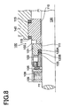
- a mechanical seal 100 is located between a rotary shaft 130 and a housing 140.
- the mechanical seal 100 is used for sealing a fluid in pumps, refrigerators or the like.
- a seal ring 101 made of sintered porous silicon carbide is fitted over the rotary shaft 130.
- the rotary seal ring 101 retains a seal face 102 on its side surface.
- packings 120A, 120B are disposed in a step shoulder 103 of the inner diameter surface of the rotary seal ring 101 to seal against the rotary shaft 130.
- the packings 120A, 120B are pressed by a gland ring 105 and seal the interface of the rotary shaft 130 and the rotary ring 101.
- a support ring 109 which is fixed to the rotary shaft 130 by means of a socket screw 108 supports a spring element 106, and the gland ring 105 is resiliently urged by the spring element 106.
- An opposing seal face 111 which forms a slidably sealing contact with the seal face 102 is disposed in a fixed ring 110.
- the fixed ring 110 is secured via O-rings 115,115 to a bore of the housing 140 through which the rotary shaft 130 extends.
- This fixed ring 110 is made of carbon.
- the seal ring 101 and the fixed seal ring 110 slide with respect to each other while maintaining a sealing therebetween in order to seal a higher pressure side P1 from a lower pressure side P2.
- the seal ring 101 has a sintered silicon carbide body in which spherical pores whose average diameter is in a range of from 0.010 mm to 0.040 mm are spread within its crystalline structure and a lubricant captured inside the pores improves its sliding resistance.
- the pores located in the sliding face of the sintered silicon carbide body are fabricated by adding polystyrene beads in a pre-sintering process and then resolving and sublimating them in a temporary sintering. This process provides a sintered silicon carbide body with a plurality of pores isolating from each other and scattered inside the crystalline structure of crystal grains. From a fabrication standpoint, a difficulty in high compression moulding causes a decrease in dimensional accuracy of the moulded product.
- polystyrene beads resolved in the sintering process decreases strength of a sintered material as a sliding element. These pores are simply arranged at random on the sliding face and a mere preservation of lubricant in the pores does not yield decrease of the friction coefficient of the sliding face as expected.
- This mechanical seal has the same constitution as that shown in Fig. 8.
- the sliding face of a fixed ring, not shown in the figure, retained in the housing forms a sealing contact with the sliding face of a driven ring securely attached to the rotary shaft as shown in Fig. 9 for sealing a process fluid.
- the sliding face 155A of the driven ring 155 retains a lot of concavities 156.
- Minimum width of the concavity 156 is in a range of from 30x10 -6 m to 100x10 -6 m while the maximum width is in a range of from 60x10 6 m to 500x100 -6 m. Moreover, the maximum width is more than twice in dimension of the minimum width.
- the concavities 156 are orientated at random relative to a rotational direction of the sliding face 155A.
- the concavities 156 serve a purpose of retaining a process fluid which enters into between the sliding face 155A of the driven ring 155 and the sliding face of the fixed ring. That is, the process fluid entering from the outer circumference side of the driven ring is trapped and stored in the concavity 156 before the fluid reaches the inner circumference edge.
- the fluid stored in the concavity 156 is pushed toward the circumferentially backward direction of the concavity 156 due to viscosity of the fluid and rotary motion of the driven ring, and a portion of the fluid exceeding the storage capacity of the concavity starts to leak from the outer circumferential edge of the concavity 156, which moves between the relatively sliding faces and is eventually trapped by an adjacent concavity 156.
- the process fluid is pushed toward the outer circumferential edge and to the backward direction relative to the rotary motion of the sliding faces.
- the dimension of the concavity 156 is so small not only that it can not provide enough force to retain the process fluid on the sliding face but also that it does not induce enough pumping effect to push back the process fluid to where it comes from. Therefore, neither decrease of the friction coefficient of the sliding face of the driven ring 156 nor decrease of the heat generation due to sliding friction can be expected. Also it is difficult to reduce a sliding resistance in case of a slow rotational speed of the driven ring.
- the sliding face of the sliding element for mechanical seals disposes a plurality of dimples lined up like a groove along a longitudinal direction which is vertical to a sliding direction.
- Dynamic pressure generated within the dimples is fairly large.
- a lubricant oil film of the fluid formed is so thin that the lubricant oil preserved in the dimples does not provide a long-term reduction effect of the friction coefficient of the sliding faces.
- a primary technical object which this invention tries to achieve is to form a film of process fluid on a sliding face for reducing a frictional resistance and enhancing a seal performance. Another object is to prevent heat generation on the sliding face. Yet another object is to prevent a wear of the sliding face for a long-term assurance of the performance of the sliding faces.
- Yet another object is not only to prevent a decrease of a seal performance of the sliding element at a slow rotational speed but also to reduce a frictional resistance at such a slow speed.
- a primary object of the present invention is to resolve the above mentioned technical problems, and a solution to such problems is embodied as follows.
- a preferred embodiment of a sliding element constructed in accordance with the principles of the present invention is a sliding element ⁇ for providing a seal against a process fluid between sliding faces of a pair of relatively slidable components, one of the components being a stationary sliding element and the other being a rotary sliding element, and the process fluid being located around either inner circumference or outer circumference of the sliding faces.
- a first sliding face of a pair of sliding faces is located on the process fluid side and a second sliding face is on the other side.
- the first sliding face has dimples whose longitudinal direction is inclined relative to a tangential line which is defined with respect to a rotational direction of the sliding face.
- the second sliding face is a plane surface or has second dimples which are smaller than the dimples on the first sliding face.
- a sliding element comprising sliding face regions for providing a seal against a process fluid being located in either an inner circumference or an outer circumference of said sliding face regions, in combination with a second sliding element, one of said elements being a stationary sliding element and the other of said elements being a rotary sliding element, a first sliding face region of said sliding face regions being located on a side of the sliding element to react with the process fluid; first dimples being disposed on said first sliding face region, the maximum length direction of said first dimples being orientated at an inclined angle relative to a tangent of a rotational circumference of the sliding element, a longitudinal direction of said first dimples being aligned with said inclined angle, said first dimples being inclined such that a leading edge of each said first dimple relative to the intended direction of rotation and relative to the tangent of said circumference is adjacent to a circumferential edge of the sliding element, said circumferential edge being located is use toward said process fluid; and a second sliding face region of said sliding
- Sealing the lubricant film formed on the first sliding face region by means of the second sliding face region is expected to exhibit an improved seal performance against the fluid as well as a lubrication effect.
- it in case of a low rotational speed of the sliding face, it not only enhances the seal performance but also decreases the friction coefficient.
- the sliding element may be a sliding element for providing a seal against a process fluid between sliding faces of a pair of relatively slidable components, one of the components being a stationary sliding element and the other being a rotary sliding element, and the process fluid being located around either inner circumference or outer circumference of the sliding faces.
- One of the sliding faces which is located in the process fluid side is a first sliding face and the other which is located in the opposite side of the process fluid is a second sliding face. Both sliding faces are referred to in the claims as "sliding face regions”.
- a plurality of at least one kind of dimples are disposed on the first sliding face in which the shape of the dimples is either elliptic or rectangle and the longitudinal direction of the dimples is inclined relative to a tangential line which is defined with respect to the intended direction of rotary motion of the first sliding face such that the leading edge of each dimple along its longitudinal direction becomes closer to a circumferential edge which is located in the process fluid side.
- a maximum width is in a range of from 100x10 -6 m to 1000x10 -6 m
- a longitudinal length is more than 500x10 -6 m which is larger than the width as well as smaller than the radial length of the first sliding face.
- Groove depth of the dimple is in a range of from 1x10 -6 m to 25x10 -6 m, and the second sliding face either has a plane surface or has second dimples on its face which are smaller than the dimples on the first sliding face.
- the dimples disposed on the first sliding face decreases the friction coefficient of the sliding face, and the lubricant film formed on the first sliding face sealed by the second sliding face is expected to exhibit an improved seal performance against the fluid as well as a lubrication effect.
- a friction coefficient of the sliding face is decreased while seal performance of the sliding face against the process fluid is enhanced as well.
- the sliding element exhibits both a good seal performance against the fluid and a reduced friction coefficient at a low rotational speed.
- the sliding element may be a sliding element for providing a seal against a process fluid between sliding faces of a pair of relatively slidable components, one of the components being a stationary sliding element and the other being a rotary sliding element, and the process fluid being located around either inner circumference or outer circumference of the sliding faces.
- One of the faces is a first sliding face and second sliding faces are located on both sides of the first sliding face.
- a plurality of at least one kind of dimples are disposed on the first sliding face in which the shape of the dimples is either elliptic or rectangle and the longitudinal direction of the dimples is inclined relative to a tangential line which is defined with respect to the intended direction of rotary motion of the first sliding face such that the leading edge of each dimple along its longitudinal direction becomes closer to a circumferential edge which is located in the process fluid side.
- a maximum width is in a range of from 100x10 -6 m to 1000x10 -6 m
- a longitudinal length is more than 500x10 -6 m which is larger than the width as well as smaller than the radial length of the first sliding face.
- Groove depth of the dimple is in a range of from 1x10 -6 m to 25x10 -6 m, and the second sliding face either has a plane surface or has second dimples on its face which are smaller than the dimples on the first sliding face.
- This form of sliding element sucks or draws in a process fluid onto a first sliding face and sealingly retains a lubricant film formed on the first sliding face by means of a second sliding face for not only exhibiting a lubrication effect but also significantly improving a seal performance against the process fluid with the first sliding face and the second sliding face which is located in the opposite side of the fluid.
- the sliding face significantly enhances its seal performance against the process fluid.
- the sealed lubricant film is able to decrease a friction coefficient of the sliding face. Also, in case of a low rotational speed of the sliding face, it not only enhances the seal performance but also drastically decreases the friction coefficient.
- a sliding element can retain a plurality of dimple arrays each of which consists of dimples being disposed along a radial line. These dimple arrays are radially disposed along a circumferential direction.
- dimples disposed on the first sliding face may be inclined toward the process fluid side and orderly located in a radial direction as well as in a circumferential direction. Therefore, the process fluid is evenly introduced onto the sliding face and a uniform lubricant film of the fluid retained between the sliding faces acts to maintain a low friction coefficient.
- the second seal faces also achieve an outstanding seal performance.
- the sliding element may retain the second dimples whose shape is a circle, square, rhomboid, or a rectangle or an ellipsoid which is aligned with a diametric or axial direction.
- dimples disposed on the first sliding face can evenly introduce and retain the process fluid onto the sliding face
- the second sliding face may dispose dimples whose shape is a circle, square, rhomboid, or a rectangle or an ellipsoid which is aligned with a diametric or axial direction. Therefore, a pumping effect for pushing back the lubricant film introduced onto the first sliding face toward the second sliding face will not only improve the seal performance but also decrease the friction coefficient.
- the second sliding face will enhance its seal performance by means of small dimples.
- the sliding element may have a first sliding face disposing dimples whose radial width relative to the entire radial width of the sliding face is made in a range of from 0.25 to 0.75.
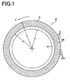
- Fig. 1 shows the arrangement of dimples 5 disposed on a sliding face 3 of a sliding element 2.
- the sliding element 2 seals a process fluid which is located on one side of the element.
- the element for example, is installed in a mechanical seal or the like.
- sliding element 2 for the arrangement shown in Fig. 1 rotates in a counter-clockwise manner. That is, this sliding element 2 disposes the first sliding face 3A with dimples either in the process fluid side or in the lubricant oil side.
- the sliding face 3 of the sliding element 2 is defined by a circumferential region with a radius in a range of from r1 to rL in which a portion of the region with a radius in a range of from r1 to r2 defines a first sliding face 3A having dimples.
- the first sliding face 3A with dimples disposes dimples 5 which are directly prepared on the sliding element 2 starting from near the outer circumferential edge of the radius r1.
- the shape of the dimples 5 is rectangular when viewed from above relative to the first sliding face 3A with dimples.
- This rectangular dimple 5 is arranged in such a way that a forward or leading edge 5A1 relative to a rotational direction N (see Fig. 4) is inclined outwardly by 30 degrees with respect to a tangential line for the circle with the rotational direction N.
- Inclined angle C of the dimple 5 is in a range of from 10 to 80 degrees, preferably from 16 to 55 degrees.
- the dimples 5 are further arranged such that a plurality of dimple arrays 5A are radially disposed on the first sliding face 3A as shown in Fig. 1.
- a plane second sliding face R1 which does not have dimples 5 is located in the inner circumferential side of the sliding face 3.
- the plane second sliding face R1 is defined by a region with a radius in a range of from r2 to rL.
- the sliding face 3 consists of the first sliding face 3A with dimples and the plane sliding face R1.
- the first sliding face 3A with dimples is designed so as to improve the seal performance as well as to reduce the friction coefficient.
- the sliding face 3A and the plane second sliding face R1 are separated with respect to a circle with a radius r2 which is defined as a boundary reference circle.
- the ratio of the first sliding face 3A with dimples over the sliding face 3 is chosen to be 0.25, 0.5, 0.75 or 1.0.
- the sliding element 2 can be made of a hard material such as super hard alloy, silicon carbide, ceramic and so on.
- silicon carbide or the like is preferred for the sliding element 2. That is, not only the strength of the sliding element 2 is enhanced but also anti-abrasion ability of the sliding face is improved.
- a sintered material retaining porosities suffers from abrasion of the sliding face and leakage of a lubricant oil or process fluid penetrating through the sliding material.
- a sliding element 2 of the present construction effectively avoids the problem.
- One of the methods for fabricating dimples 5 on the sliding face made of the hard material is a sand blasting in which a photosensitive film for sand blasting is closely placed on the sliding face.
- a photosensitive film for sand blasting is placed on the sliding face 3.
- a positive film on which arrays of dimples 5 are printed is closely placed on the photosensitive film, and the photosensitive film is subjected to an exposure.
- the photosensitive film then is developed and a subsequent sand blasting provides dimples which are identical to those printed on the positive film.
- the form of the dimple 5 as a first example is arranged to have semicircles at its both ends as shown in Fig. 4.
- Another form as a second example is a rectangle, which is not illustrated.
- Width A of the rectangular dimple 5 is in a range of from 150x10 -6 m to 1000x10 -6 m. Specific examples for the width A is 150x10 -6 m or 250x10 -6 m.
- Longitudinal length B of the dimple 5 is more than twice of the width A and less than the width of the sliding face 3.
- a typical length B of the dimple array B is 600x10 -6 m or 1000x10 -6 m.
- a depth of the dimple 5 is in a range of from 1x10 -6 m to 25x10 -6 m.
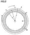
- Fig. 2 shows a second embodiment of the present invention in which a first sliding face 3B with dimples 5 is located toward the inner circumferential side relative to the boundary reference circle of radius r1.
- the forward or leading edge 5A1 of the dimple 5 relative to a rotational direction N of the sliding face 3 is inclined inwardly with respect to the rotational direction N.
- the dimples 5 of the first sliding face 3B are arranged in a radial manner with respect to the axial centre similarly to the dimples shown in Fig. 1.
- Dimples 5 disposed in the inner circumferential side of the first sliding face 3B cover from near the inner circumferential edge through the entire area of the first sliding face 3B with dimples. Thus, it allows a process fluid located in the inner circumferential side to flow in.
- the shape of the dimples 5 is rectangular when viewed from above. This rectangular dimple 5 is arranged in such a way that the forward or leading edge 5A1 relative to a rotational direction N is inclined inwardly by 25 degrees with respect to a tangential line for the circle with the rotational direction. Inclined angle C of the dimple 5 is in a range of from 10 to 80 degrees, preferably from 16 to 55 degrees.
- the dimples 5 are further arranged such that a plurality of dimple arrays 5A are radially disposed on the first sliding face 3B as shown in Fig. 2.
- Inclination angle C of the dimple 5 is made 20 or 30 degrees with respect to a tangential line of a rotational circle.
- the inclination angle C is determined based on the design of a friction coefficient, seal ability and so on. It is known that decreasing this inclination angle C leads to improved seal ability. It also is seen that increasing the angle C tends to decrease the friction resistance.
- the inclination angle C of the dimple 5 is in a range of from 10 to 80 degrees, preferably from 16 to 55 degrees for having an effect of friction coefficient reduction.
- Fig. 3 shows a sliding element 2 as a third embodiment related to the present construction.
- Inclined angle of the dimples 5 in Fig. 3 is approximately 30 degrees.
- the inclined angle C of the dimples 5 is in a range of from 10 to 80 degrees, preferably in a range of from 16 to 55 degrees.
- a first sliding face 3C with dimples is defined in a range of the radius r1 to r2 out of the sliding face 3.
- An outer circumferential area in a range of rh to r1 and an inner circumferential area in a range of r2 to rL relative to the first sliding face 3C with dimples are plane surfaces defined as a second sliding face R1.
- the plane second sliding face R1 which disposes dimples 6 which are smaller than dimples 5 of the first sliding face 3C yielded good results.
- one of the two second sliding faces R1, R1 which is located on the process fluid side retains the second dimples 6 on its surface and the other second sliding face R1 is made a plane surface.
- the second sliding face R1 on the fluid side is made plane and the other second sliding face R1 retains the second dimples 6.
- the form of the dimple 5 disposed on the first sliding face 3C may be made rectangular, elliptical, guitar-form or cruciform. Other forms and material are more or less the same as the sliding element 2 shown in Fig. 1.
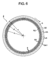
- Fig. 6 shows a sliding element 2 as a fourth embodiment related to the present invention.
- a process fluid is assumed to be located in the outer circumferential side of the sliding element 2.
- the sliding element 2 is mounted in a mechanical seal or the like and retains a first sliding face 3D with dimples in the fluid side.
- the sliding element 2 is installed in a bearing or the like in which a first sliding face 3D with dimples is disposed on the lubricant side for sliding relative to a rotary shaft by retaining the lubricant on the sliding face.
- the sliding element 2 rotates in a clockwise manner as shown in Fig. 6. That is, this sliding element 2 disposes the first sliding face 3D with dimples either in the process fluid side of the mechanical seal or in the lubricant oil side of the bearing.
- the sliding face 3 of the sliding element 2 is defined by a circumferential region with a radius in a range of from r1 to rL in which a portion of the region with a radius in a range of from r1 to r2 defines a first sliding face 3D having dimples.
- the first sliding face 3D with dimples disposes dimples 5 which are directly prepared on the sliding element 2 starting from near the outer circumferential edge of the radius r1 to an inward direction.
- the shape of the dimples 5 is rectangular when viewed from above relative to the first sliding face 3D with dimples.
- This rectangular dimple 5 is arranged in such a way that the forward or leading edge 5A1 relative to a rotational direction N is inclined outwardly by 30 degrees with respect to a tangential line for the rotational circle of the sliding face 3.
- Inclined angle C of the dimple 5 is in a range of from 10 to 80 degrees, preferably from 16 to 55 degrees.
- Three dimples 5 which are thus formed define a dimple array 5A in which the three dimples 5 are disposed along a radial line in an equally spaced manner.
- the dimples 5 are further arranged such that a plurality of dimple arrays 5A are radially disposed on the first sliding face 3D as shown in Fig. 6.
- a second sliding face R2 which is located in the inner circumferential side of the sliding face 3 disposes second dimples 6 whose shape is smaller than the maximum length of the dimple 5 as shown in Fig. 6.
- the form of the second dimple 6 may be that of a circle, square, rhombus, ellipse or rectangle, which is not inclined radially or axially, and there include a plurality of the second dimples 6 which take one or more than one of these forms.
- a plurality of the second dimples 6 form a dimple array 6A radially disposed on the second sliding face R2. Furthermore, a plurality of such dimple arrays 6A are radially arranged in an equally spaced manner along the circumferential direction. When the second dimples 6 are small in size, the dimples 6 may be disposed at random on the second sliding face R2.
- the second sliding face R2 is defined by a region with a radius in a range of from r2 to rL.
- the sliding face 3 consists of the first sliding face 3D with dimples and the second sliding face R2.
- the first sliding face 3D with dimples is designed so as to improve the seal performance as well as to reduce the friction coefficient.
- the first sliding face 3D with dimples and the second sliding face R2 are separated with respect to a circle with a radius r2 which is defined as a boundary reference circle.
- the ratio of the first sliding face 3D with dimples over the sliding face 3 is chosen to be 0.25, 0.5, 0.75 or 1.0.
- the sliding element 2 can be made of a hard material such as super hard alloy, silicon carbide, ceramic and so on.
- silicon carbide or the like is preferred for the sliding element 2.
- silicon carbide not only the strength of the sliding element 2 is enhanced but also anti-abrasion ability of the sliding face is improved.
- Aforementioned prior art shown in Fig. 8 a sintered material retaining porosities, suffers from abrasion of the sliding face and leakage of a lubricant oil or process fluid penetrating through the sliding material.
- a sliding element 2 of the present construction effectively avoids the problem.
- One of the methods for fabricating dimples 5 on the sliding face made of the hard material is a sand blasting method in which a photosensitive film for sand blasting is closely placed on the sliding face.
- a photosensitive film for sand blasting is placed on the sliding face 3.
- a positive film on which arrays of dimples 5 are printed is closely placed on the photosensitive film, and the photosensitive film is subjected to an exposure.
- the photosensitive film then is developed and a subsequent sand blasting provides dimples which are identical to those printed on the positive film.
- the form of the dimple 5 is arranged to have semicircles at its both ends as shown in Fig. 4.
- Another form of a different example is a rectangle.
- the inclined angle C has its forward or leading edge 5A1 relative to a rotational direction facing downward (dimple 5A1 shown by a dotted line in Fig. 4) as opposed to the former case of Fig. 4.
- Width A of the rectangular dimple 5 is in a range of from 150x10 -6 m to 1000x10 -6 m. Specific examples for the width A is 150x10 -6 m or 250x10 -6 m.
- Longitudinal length B of the dimple 5 is more than 500x10 -6 m and larger than the width A and less than the width of the sliding face 3.
- a typical length B of the dimple array B is 600x10 -6 m or 750x10 -6 m.
- a typical depth of the dimple 5 is 8x10 -6 m or 10x10 -6 m.
- Fig. 7 shows a sliding element as a fifth embodiment of the present construction.
- a first sliding face 3E with dimples 5 is located toward the inner circumferential side relative to the boundary reference circle of radius r2.
- the forward edge 5A1 of the dimple 5 relative to a rotational direction N of the sliding face 3 is inclined toward the process fluid side (toward the inner diameter) with respect to the rotational direction N.
- Dimples 5 of the first sliding face 3E are arranged in a radial manner with respect to the axial centre as shown in Fig. 7.
- Dimples 5 disposed in the inner circumferential side of the first sliding face 3E cover from near the inner circumferential edge through the entire area of the first sliding face 3E with dimples. Thus, it allows a process fluid located in the inner circumferential side to flow in.
- the shape of the dimples 5 is rectangular when viewed from above. This rectangular dimple 5 is arranged in such a way that the forward edge 5A1 relative to a rotational direction N is inclined inwardly by 25 degrees with respect to a tangential line for the circle with the rotational direction. Inclined angle C of the dimple 5 is in a range of from 10 to 80 degrees, preferably from 16 to 55 degrees.
- Three dimples 5 which are thus formed define a dimple array 5A in which the three dimples 5 are disposed along a radial line in an equally spaced manner.
- the number of the dimples involved in a dimple array 5A arbitrarily varies from one to ten.
- the dimples 5 are further arranged in such a way that the dimple arrays 5A are radially disposed on the first sliding face 3E in more or less equally a spaced manner as shown in Fig. 7.
- the form of the above dimple 5 prefferably be chosen so that the form does not easily deteriorate due to abrasion dust. Therefore, the form and the orientation of the dimple 5 should be designed such that thickness of a lubrication film caused by a process fluid is increased.
- Fabrication methods of the dimple 5 other than the method previously mentioned include use of an etching process or a reaction process with other solid metals.
- the sliding element 2 can be used in a mechanical seal, bearing or the like.
- the sliding element 2 can be utilised for either a stationary seal ring or a rotary seal ring or both rings. That is, when dimples 5 are disposed on only one seal ring, the other seal ring retains a plane seal face which forms a sealing contact with the seal ring with dimples.
- the sliding element 2 can be utilised for a sliding face supporting a radial load or a thrust load exerted to a rotary shaft.
- the inclined angle C of the dimple 5 is chosen so that the lubricant oil is pumped up toward the lubricating sliding face.
- Fig. 5 is a cross-sectional view of a mechanical seal testing apparatus for evaluating the present sliding element 2.
- the testing apparatus 10 for the sliding element 2 shown in Fig. 5 retains a rotatable, cylindrical housing 20 along the centre axis.
- a stationary seal ring 11 is sealingly fitted via a O-ring to a mating surface disposed in a process fluid chamber 20A within the housing 20.
- the rotary seal ring 12 is resiliently urged by a spring in an axially movable manner relative to a retainer 13 which is fixed to the rotary shaft 15. And the sealing contact of the seal face of the rotary seal ring 12 and the opposite seal face of the stationary seal ring 11 prevents the fluid inside the process fluid chamber 20A from leaking to the ambient.
- a drain passage 15A is disposed along the axis of the rotary shaft 15 driven by a motor 16.
- a supply passage 14 is disposed inside the drain passage 15A by extending through the drain passage 15A.
- Process fluid e.g., oil
- Ends of the drain passage 15A and the supply passage 14 are connected to a circulation pipe, which is not shown in the figure, and a pump connected to the pipe circulates the fluid modulated at a specific temperature and pressure.
- the rotational speed of the motor 16 can be controlled by an inverter which is not shown in the figure.
- the housing 20 retaining the stationary seal ring 11 is fixed to the shaft 19 which is supported by a bearing 18 in a freely rotatable manner.
- the housing 20 is rotatable by a sliding friction which is caused by a relative rotation of the stationary seal ring 11 and the rotary seal ring 12.
- a hole whose diameter is 2 mm is disposed in 1mm away from the opposing seal face of the stationary seal ring 11 and the hole is connected to an end of a conductive line 17 such as PlatinumRhodium-Platinum or Alumel-Chromel whose other end is connected to a thermo-electric thermometer which is not shown in the figure. Temperature of the sliding face of the stationary seal ring 11 is measured by the thermo-electric thermometer.
- a support block which supports the shaft 19 is equipped with a load cell 21 and a sliding torque M can be measured by way of a cantilever 22.
- This testing apparatus is internal-flow unbalancing type, and the seal face is urged by the fluid pressure and the resiliently urging force of a spring. In case of a zero fluid pressure, the sliding face is urged by the spring of the retainer 13 alone. Measured items by this testing apparatus include the sliding torque M of the sliding element 2, temperature of the sliding face 3, fluid temperature and a volume of the fluid leaked through the sliding face 3.
- A represents a process fluid pressure (MPa) while B represents a ratio (%) of the friction coefficient of the present sliding element over the friction coefficient of the sliding face without dimples.
- B represents a ratio (%) of the friction coefficient of the present sliding element over the friction coefficient of the sliding face without dimples.
- A represents a process fluid pressure (MPa) while B represents a ratio (%) of the friction coefficient of the present sliding element of the present invention over the friction coefficient of the sliding face without dimples.
- B represents a ratio (%) of the friction coefficient of the present sliding element of the present invention over the friction coefficient of the sliding face without dimples.
- A represents a process fluid pressure (MPa) while B represents a ratio (%) of the friction coefficient of the present sliding element over the friction coefficient of the sliding face without dimples.
- B represents a ratio (%) of the friction coefficient of the present sliding element over the friction coefficient of the sliding face without dimples.
- Examples 1 to 5 are compared with the reference case while a fluid leakage is being kept within a permissible range.
- the friction coefficient of the reference case relative to the friction coefficient observed for a sliding between two plane sliding faces is in a range of from 77% to 93%.
- Example 1 exhibits a range of 57% to 84%, Example 2 12% to 36%, Example 3 44% to 83%, Example 4 43% to 68%, Example 5 44% to 66% and Example 6 44% to 58%. That is, the friction coefficient can be significantly decreased compared with the reference case.
- a small pressure of the process fluid can further decrease the friction coefficient. Also increasing the length of the dimples 5 is expected to decrease the friction coefficient. A slow rotational speed of the sliding element 2 is effective for reducing the friction coefficient as well.
- the width is more than 100x10 -6 m and less than 1000 x10 -6 m and the length is more than 500x10 -6 m and longer than the width of the dimple 5 and shorter than the radial width of the sliding face 3.
- the depth of the dimple 5 is in a range of from 1x10 -6 m to 25x10 -6 m.
- the shape of the dimple 5 thus created is preferably rectangular, elliptical, guitar-form or cruciform.
- This sliding element 2 is suitable for a seal ring of mechanical seal used in a chemical reactor or the like.
- the element 2 is even more effective when the sliding face 3 of the seal ring is subjected to a slow rotational speed and the fluid pressure is rather high.
- the forward edge of the dimple of the first sliding face relative to a tangential line with respect to the rotational direction is inclined for optimally sucking or drawing in a process fluid such that the process fluid introduced between the dimples on the sliding face creates a lubricant film of the fluid.
- the lubricant film of the fluid then remains on the first sliding face by being sealed by the second sliding face.
- the friction coefficient of the sliding face is decreased by the lubricant film. Therefore, heat generation of the sliding face is reduced as well. This leads to an effective prevention of abrasion and damage of the sliding face.
- the sliding element has a first sliding face with dimples and a plane second sliding face which is located in the opposite side of the process fluid with respect to the first sliding face.
- the second sliding face reduces the friction coefficient by sealing and uniformly retaining the process fluid on the first sliding face but also effectively seals the fluid by collaborating with the first sliding face.
- the sliding element not only can decrease the friction coefficient but also reduce a squeaking noise or a linking or clanking during sliding as a result of preventing abrasion of the sliding faces.
- use of the sliding element with an opposing sliding element being made of carbon material can prevent a blistering effect, hence a resulting improved seal performance against the process fluid.
Landscapes
- Engineering & Computer Science (AREA)
- General Engineering & Computer Science (AREA)
- Mechanical Engineering (AREA)
- Mechanical Sealing (AREA)
Claims (6)
- Gleitelement (2), umfassend Gleitflächenbereiche (3) zur Bereitstellung einer Abdichtung gegen ein Prozessfluid, das sich entweder an einem Innenumfang oder an einem Außenumfang der Gleitflächenbereiche (3) befindet, zur Verwendung in Kombination mit einem zweiten Gleitelement, wobei eines der Elemente ein stationäres Gleitelement ist, und das andere der Elemente ein sich drehendes Gleitelement ist,
wobei sich ein erster Gleitflächenbereich (3A) der Gleitflächenbereiche an einer Seite des Gleitelements befindet, um mit dem Prozessfluid zu regieren;
erste Vertiefungen (5), die am ersten Gleitflächenbereich angeordnet sind, wobei die maximale Längsrichtung der ersten Vertiefungen in einem schrägen Winkel in Bezug auf eine Tangente eines Drehumfangs des Gleitelements ausgerichtet ist, wobei eine Längsrichtung der ersten Vertiefungen mit dem schrägen Winkel ausgerichtet ist, wobei die ersten Vertiefungen so geneigt sind, dass sich eine Vorderkante jeder ersten Vertiefung in Bezug auf die beabsichtigte Drehrichtung (N) in Verwendung und in Bezug auf die Tangente des Umfangs neben einem Umfangsrand des Gleitelements befindet, wobei sich der Umfangsrang in Verwendung zum Prozessfluid hin befindet; und
sich ein zweiter Gleitflächenbereich (R1) der Gleitflächenbereiche an der radial entgegengesetzten Seite des Gleitelements befindet, um sich vom Prozessfluid entfernt zu befinden, wobei der zweite Gleitflächenbereich entweder eine flache Oberfläche oder haltende zweite Vertiefungen (6) aufweist, wobei die zweiten Vertiefungen kleiner als die ersten Vertiefungen sind,
wobei die ersten Vertiefungen so angeordnet sind, dass sie radiale Linien bilden,
wobei mehrere der radialen Linien entlang einer Umfangsrichtung angeordnet sind,
wobei entlang jeder der radialen Linien zumindest zwei Vertiefungen vorgesehen sind, um mehrere Kreise der ersten Vertiefungen zu bilden, und
wobei alle ersten Vertiefungen die gleiche längsgerichtete Länge aufweisen. - Gleitelement (2) nach Anspruch 1, wobei die ersten Vertiefungen entweder eine elliptische Form oder eine rechteckige Form aufweisen,
wobei die Höchstbreite jeder ersten Vertiefung in einem Bereich von 100x10-6 m bis 1000x10-6 m liegt, die längsgerichtete Länge jeder Vertiefung in einem Bereich von mehr als 500x10-6 m liegt und größer als die Breite der Vertiefung und kleiner als die radiale Breite der ersten Gleitfläche ist, und die Tiefe der ersten Vertiefung in einem Bereich von 1x10⁻⁶ m bis 25x10 -6 m liegt. - Gleitelement (2) nach Anspruch 1, wobei sich die zweiten Gleitflächenbereiche (R1) der Gleitflächenbereiche am inneren und am äußeren Umfang des ersten Gleitflächenbereichs befinden.
- Gleitelement (2) nach Anspruch 1, 2 oder 3, wobei die ersten Vertiefungen entlang einer Durchmesserrichtung in mehreren Vertiefungsanordnungen (5A) angeordnet sind, und die Vertiefungsanordnungen entlang der Umfangsrichtung radial angeordnet sind.
- Gleitelement (2) nach Anspruch 3, wobei die Form jeder zweiten Vertiefung (6) ein Kreis, ein Quadrat, ein Parallelogramm oder ein Rechteck oder ein Ellipsoid ist, der bzw. das mit einer diametralen oder axialen Richtung ausgerichtet ist.
- Gleitelement (2) nach Anspruch 1, 2 oder 3, wobei ein Verhältnis der radialen Breite einer ersten Gleitfläche, die die Vertiefungen aufweist, zur radialen Breite der Gleitfläche in einem Bereich von 0,25 bis 0,75 liegt.
Applications Claiming Priority (4)
| Application Number | Priority Date | Filing Date | Title |
|---|---|---|---|
| JP2002100512 | 2002-04-02 | ||
| JP2002100512 | 2002-04-02 | ||
| JP2002219792 | 2002-07-29 | ||
| JP2002219792A JP4205910B2 (ja) | 2002-04-02 | 2002-07-29 | 摺動部品 |
Publications (3)
| Publication Number | Publication Date |
|---|---|
| EP1350996A2 EP1350996A2 (de) | 2003-10-08 |
| EP1350996A3 EP1350996A3 (de) | 2004-06-16 |
| EP1350996B1 true EP1350996B1 (de) | 2008-01-09 |
Family
ID=28043862
Family Applications (1)
| Application Number | Title | Priority Date | Filing Date |
|---|---|---|---|
| EP03252108A Expired - Lifetime EP1350996B1 (de) | 2002-04-02 | 2003-04-02 | Gleitelement |
Country Status (4)
| Country | Link |
|---|---|
| US (1) | US7500676B2 (de) |
| EP (1) | EP1350996B1 (de) |
| JP (1) | JP4205910B2 (de) |
| DE (1) | DE60318511T2 (de) |
Cited By (1)
| Publication number | Priority date | Publication date | Assignee | Title |
|---|---|---|---|---|
| CN104165228A (zh) * | 2014-07-25 | 2014-11-26 | 浙江工业大学 | 一种似含羞草型孔簇端面机械密封结构 |
Families Citing this family (50)
| Publication number | Priority date | Publication date | Assignee | Title |
|---|---|---|---|---|
| JP4316956B2 (ja) * | 2002-10-23 | 2009-08-19 | イーグル工業株式会社 | 摺動部品 |
| JP4602779B2 (ja) * | 2005-02-01 | 2010-12-22 | 帝人ファーマ株式会社 | 回転バルブ |
| JP5580532B2 (ja) * | 2006-07-25 | 2014-08-27 | イーグル工業株式会社 | メカニカルシール装置 |
| US8360436B2 (en) | 2008-01-11 | 2013-01-29 | Eagle Industry Co., Ltd. | Mechanical seal sliding member, and mechanical seal |
| US9784372B2 (en) | 2009-05-25 | 2017-10-10 | Eagle Industry Co., Ltd. | Sealing device |
| JP5530739B2 (ja) * | 2010-02-10 | 2014-06-25 | 日本ピラー工業株式会社 | メカニカルシール用密封環とその製造方法 |
| JP5530738B2 (ja) * | 2010-02-10 | 2014-06-25 | 日本ピラー工業株式会社 | メカニカルシール |
| JP5518527B2 (ja) * | 2010-03-04 | 2014-06-11 | イーグル工業株式会社 | 摺動部品 |
| EP2545308B1 (de) * | 2010-03-12 | 2017-06-07 | Aktiebolaget SKF | Reibungsarme dichtung |
| CN101975274B (zh) * | 2010-11-03 | 2012-11-21 | 浙江工业大学 | 一种自密封零泄漏疏水型面机械密封端面结构 |
| CN103732957B (zh) * | 2011-09-03 | 2016-04-13 | 伊格尔工业股份有限公司 | 滑动部件 |
| US10793114B2 (en) | 2011-11-18 | 2020-10-06 | Trico Products Corporation | Windscreen wiper device |
| WO2013176011A1 (ja) * | 2012-05-21 | 2013-11-28 | イーグル工業株式会社 | 摺動部品 |
| JP6407728B2 (ja) * | 2013-02-07 | 2018-10-17 | 株式会社タンケンシールセーコウ | メカニカルシールの製造方法 |
| CN103470762B (zh) * | 2013-08-20 | 2016-05-18 | 浙江工业大学 | 倾斜渐变多孔端面非接触式机械密封结构 |
| EP3039317B1 (de) * | 2013-08-27 | 2020-02-26 | Eaton Corporation | Dichtungsringverbund mit verbesserter hydrodynamischer dichtungsleistungsfähigkeit |
| US9970478B2 (en) | 2013-09-18 | 2018-05-15 | Eagle Industry Co., Ltd. | Sliding parts |
| US9829043B2 (en) | 2013-09-18 | 2017-11-28 | Eagle Industry Co., Ltd. | Sliding parts |
| US9714712B2 (en) | 2014-08-15 | 2017-07-25 | Eaton Corporation | Hydrodynamic mating ring with integrated groove inlet pressure control |
| JP6683630B2 (ja) * | 2015-02-14 | 2020-04-22 | イーグル工業株式会社 | しゅう動部品 |
| JP6776232B2 (ja) * | 2015-06-15 | 2020-10-28 | イーグル工業株式会社 | 摺動部品 |
| JP6798776B2 (ja) * | 2015-10-16 | 2020-12-09 | 株式会社リケン | シールリング |
| WO2018043307A1 (ja) * | 2016-09-01 | 2018-03-08 | イーグル工業株式会社 | しゅう動部品 |
| US10808752B2 (en) * | 2016-11-18 | 2020-10-20 | Eagle Industry Co., Ltd | Sliding members |
| US11125334B2 (en) | 2016-12-21 | 2021-09-21 | Eaton Intelligent Power Limited | Hydrodynamic sealing component and assembly |
| KR102346413B1 (ko) * | 2017-05-19 | 2022-01-03 | 이구루코교 가부시기가이샤 | 슬라이딩 부품 |
| KR102346395B1 (ko) * | 2017-05-19 | 2022-01-03 | 이구루코교 가부시기가이샤 | 슬라이딩 부품 |
| KR102346371B1 (ko) * | 2017-05-19 | 2022-01-03 | 이구루코교 가부시기가이샤 | 슬라이딩 부품 |
| EP3421807A1 (de) * | 2017-06-29 | 2019-01-02 | Koninklijke Philips N.V. | Vorrichtung mit einer zum treffen mit rotierender luft angeordnete fläche |
| KR102459648B1 (ko) * | 2017-07-14 | 2022-10-28 | 이구루코교 가부시기가이샤 | 슬라이딩 부품 |
| EP3693638A4 (de) | 2017-10-03 | 2021-06-23 | Eagle Industry Co., Ltd. | Gleitkomponente |
| US11608897B2 (en) | 2018-08-01 | 2023-03-21 | Eagle Industry Co., Ltd. | Slide component |
| CN109058156B (zh) * | 2018-08-17 | 2024-12-06 | 浙江工业大学 | 一种似梳子动静压组合型机械密封端面结构 |
| EP3842673A4 (de) | 2018-08-24 | 2022-05-04 | Eagle Industry Co., Ltd. | Gleitelement |
| CN112739941B (zh) | 2018-10-01 | 2023-11-14 | 伊格尔工业股份有限公司 | 滑动部件 |
| WO2020085122A1 (ja) | 2018-10-24 | 2020-04-30 | イーグル工業株式会社 | 摺動部材 |
| EP4198353B1 (de) | 2018-11-30 | 2025-03-12 | Eagle Industry Co., Ltd. | Schiebekomponente |
| EP3901497B1 (de) | 2018-12-21 | 2024-08-21 | Eagle Industry Co., Ltd. | Gleitkomponente |
| KR102610647B1 (ko) | 2019-02-04 | 2023-12-07 | 이구루코교 가부시기가이샤 | 슬라이딩 부품 |
| KR102639196B1 (ko) | 2019-02-14 | 2024-02-21 | 이구루코교 가부시기가이샤 | 슬라이딩 부품 |
| WO2020171102A1 (ja) | 2019-02-21 | 2020-08-27 | イーグル工業株式会社 | 摺動部品 |
| IT201900010977A1 (it) * | 2019-07-05 | 2021-01-05 | Ml Engraving S R L | Guarnizione, stampo, macchina laser, metodo per realizzare detto stampo, metodo per realizzare detta guarnizione |
| US11892081B2 (en) | 2019-07-26 | 2024-02-06 | Eagle Industry Co., Ltd. | Sliding component |
| EP4102112B1 (de) | 2020-04-07 | 2025-02-26 | Eagle Industry Co., Ltd. | Gleitkomponente |
| KR102744483B1 (ko) * | 2020-04-07 | 2024-12-18 | 이글 고오교 가부시키가이샤 | 슬라이딩 부품 |
| WO2021246372A1 (ja) | 2020-06-02 | 2021-12-09 | イーグル工業株式会社 | 摺動部品 |
| US12276338B2 (en) | 2020-06-02 | 2025-04-15 | Eagle Industry Co., Ltd. | Sliding component |
| US12247666B2 (en) | 2021-03-12 | 2025-03-11 | Eagle Industry Co., Ltd. | Sliding component |
| KR20240019290A (ko) | 2021-07-13 | 2024-02-14 | 이구루코교 가부시기가이샤 | 슬라이딩 부품 |
| JPWO2023053964A1 (de) | 2021-09-28 | 2023-04-06 |
Family Cites Families (18)
| Publication number | Priority date | Publication date | Assignee | Title |
|---|---|---|---|---|
| JPS57161368A (en) * | 1981-03-31 | 1982-10-04 | Eagle Ind Co Ltd | Mechanical seal |
| JPS57163770A (en) * | 1981-04-01 | 1982-10-08 | Eagle Ind Co Ltd | Mechanical seal |
| JPS59231269A (ja) * | 1983-06-14 | 1984-12-25 | Arai Pump Mfg Co Ltd | メカニカルシ−ル |
| US4645414A (en) * | 1985-06-07 | 1987-02-24 | General Motors Corporation | Combined vacuum pump, bearing and seal assembly |
| CH677266A5 (de) * | 1986-10-28 | 1991-04-30 | Pacific Wietz Gmbh & Co Kg | |
| DE3819566A1 (de) * | 1988-06-09 | 1989-12-14 | Kernforschungsz Karlsruhe | Spaltdichtung |
| JPH0255273A (ja) | 1988-08-18 | 1990-02-23 | Showa Denko Kk | メカニカルシール用炭化珪素焼結体およびそれを用いたメカニカルシール |
| US5492341A (en) * | 1990-07-17 | 1996-02-20 | John Crane Inc. | Non-contacting, gap-type seal having a ring with a patterned seal face |
| JPH0743038B2 (ja) * | 1990-07-18 | 1995-05-15 | 株式会社荏原製作所 | 非接触端面シール |
| JPH04145267A (ja) * | 1990-10-08 | 1992-05-19 | Ebara Corp | 非接触端面シール |
| JP3026252B2 (ja) * | 1995-09-08 | 2000-03-27 | イーグル工業株式会社 | メカニカルシール用摺動材 |
| US5834094A (en) * | 1996-09-30 | 1998-11-10 | Surface Technologies Ltd. | Bearing having micropores and design method thereof |
| US6149160A (en) * | 1997-08-08 | 2000-11-21 | Board Of Supervisors Of Louisiana State University And Agricultural And Mechanical College | Mechanical seals enhanced with microstructures |
| US6152452A (en) * | 1997-10-17 | 2000-11-28 | Wang; Yuming | Face seal with spiral grooves |
| JPH11236976A (ja) * | 1998-02-24 | 1999-08-31 | Eagle Ind Co Ltd | 摺動材 |
| DE10004263A1 (de) * | 2000-02-01 | 2001-08-02 | Leybold Vakuum Gmbh | Dynamische Dichtung |
| US6341782B1 (en) * | 2000-03-03 | 2002-01-29 | Surface Technologies Ltd | Lubricated seals having micropores |
| US6655693B2 (en) * | 2001-04-26 | 2003-12-02 | John Crane Inc. | Non-contacting gas compressor seal |
-
2002
- 2002-07-29 JP JP2002219792A patent/JP4205910B2/ja not_active Expired - Lifetime
-
2003
- 2003-04-01 US US10/403,002 patent/US7500676B2/en not_active Expired - Lifetime
- 2003-04-02 EP EP03252108A patent/EP1350996B1/de not_active Expired - Lifetime
- 2003-04-02 DE DE60318511T patent/DE60318511T2/de not_active Expired - Lifetime
Cited By (2)
| Publication number | Priority date | Publication date | Assignee | Title |
|---|---|---|---|---|
| CN104165228A (zh) * | 2014-07-25 | 2014-11-26 | 浙江工业大学 | 一种似含羞草型孔簇端面机械密封结构 |
| CN104165228B (zh) * | 2014-07-25 | 2016-04-13 | 浙江工业大学 | 一种似含羞草型孔簇端面机械密封结构 |
Also Published As
| Publication number | Publication date |
|---|---|
| EP1350996A3 (de) | 2004-06-16 |
| US20030189294A1 (en) | 2003-10-09 |
| DE60318511T2 (de) | 2009-01-29 |
| JP4205910B2 (ja) | 2009-01-07 |
| DE60318511D1 (de) | 2008-02-21 |
| EP1350996A2 (de) | 2003-10-08 |
| JP2004003578A (ja) | 2004-01-08 |
| US7500676B2 (en) | 2009-03-10 |
Similar Documents
| Publication | Publication Date | Title |
|---|---|---|
| EP1350996B1 (de) | Gleitelement | |
| EP1347219B1 (de) | Gleitelement | |
| US20220268361A1 (en) | Sliding components | |
| EP1413807B1 (de) | Gleitelement | |
| JP6861730B2 (ja) | しゅう動部品 | |
| US5873576A (en) | Skew and twist resistant hydrodynamic rotary shaft seal | |
| EP3309431B1 (de) | Gleitbauteil | |
| EP3299685B1 (de) | Gleitkomponente | |
| US8474826B2 (en) | Hydrodynamic magnetic seal | |
| JP4495402B2 (ja) | 摺動部品 | |
| EP3508763A1 (de) | Gleitkomponente | |
| EP2752603A1 (de) | Gleitkomponente | |
| JPWO2018088350A1 (ja) | しゅう動部品 | |
| JPH11287329A (ja) | 摺動材 | |
| CN100385154C (zh) | 耐压静态和动态推出器轴密封 | |
| KR102616659B1 (ko) | 슬라이딩 부품 | |
| WO2002093046A1 (en) | Mechanical seal | |
| JP4330875B2 (ja) | シール装置 | |
| KR20090040956A (ko) | 가스터빈용 베어링 시일 | |
| JP2004060738A (ja) | 摺動部品 | |
| CN210050296U (zh) | 一种干磨式组合密封装置 | |
| JPH04101077U (ja) | シール装置 | |
| Stephens et al. | Seal Assembly for Machinery Housing | |
| JPH06265026A (ja) | 軸封装置の摺動環 |
Legal Events
| Date | Code | Title | Description |
|---|---|---|---|
| PUAI | Public reference made under article 153(3) epc to a published international application that has entered the european phase |
Free format text: ORIGINAL CODE: 0009012 |
|
| AK | Designated contracting states |
Kind code of ref document: A2 Designated state(s): AT BE BG CH CY CZ DE DK EE ES FI FR GB GR HU IE IT LI LU MC NL PT RO SE SI SK TR |
|
| AX | Request for extension of the european patent |
Extension state: AL LT LV MK |
|
| PUAL | Search report despatched |
Free format text: ORIGINAL CODE: 0009013 |
|
| AK | Designated contracting states |
Kind code of ref document: A3 Designated state(s): AT BE BG CH CY CZ DE DK EE ES FI FR GB GR HU IE IT LI LU MC NL PT RO SE SI SK TR |
|
| AX | Request for extension of the european patent |
Extension state: AL LT LV MK |
|
| 17P | Request for examination filed |
Effective date: 20040914 |
|
| 17Q | First examination report despatched |
Effective date: 20041209 |
|
| AKX | Designation fees paid |
Designated state(s): DE FR GB |
|
| GRAP | Despatch of communication of intention to grant a patent |
Free format text: ORIGINAL CODE: EPIDOSNIGR1 |
|
| GRAS | Grant fee paid |
Free format text: ORIGINAL CODE: EPIDOSNIGR3 |
|
| GRAA | (expected) grant |
Free format text: ORIGINAL CODE: 0009210 |
|
| AK | Designated contracting states |
Kind code of ref document: B1 Designated state(s): DE FR GB |
|
| REG | Reference to a national code |
Ref country code: GB Ref legal event code: FG4D |
|
| REF | Corresponds to: |
Ref document number: 60318511 Country of ref document: DE Date of ref document: 20080221 Kind code of ref document: P |
|
| ET | Fr: translation filed | ||
| PLBE | No opposition filed within time limit |
Free format text: ORIGINAL CODE: 0009261 |
|
| STAA | Information on the status of an ep patent application or granted ep patent |
Free format text: STATUS: NO OPPOSITION FILED WITHIN TIME LIMIT |
|
| 26N | No opposition filed |
Effective date: 20081010 |
|
| PGFP | Annual fee paid to national office [announced via postgrant information from national office to epo] |
Ref country code: FR Payment date: 20090417 Year of fee payment: 7 |
|
| PGFP | Annual fee paid to national office [announced via postgrant information from national office to epo] |
Ref country code: GB Payment date: 20090401 Year of fee payment: 7 |
|
| GBPC | Gb: european patent ceased through non-payment of renewal fee |
Effective date: 20100402 |
|
| REG | Reference to a national code |
Ref country code: FR Ref legal event code: ST Effective date: 20101230 |
|
| PG25 | Lapsed in a contracting state [announced via postgrant information from national office to epo] |
Ref country code: GB Free format text: LAPSE BECAUSE OF NON-PAYMENT OF DUE FEES Effective date: 20100402 |
|
| PG25 | Lapsed in a contracting state [announced via postgrant information from national office to epo] |
Ref country code: FR Free format text: LAPSE BECAUSE OF NON-PAYMENT OF DUE FEES Effective date: 20100430 |
|
| PGFP | Annual fee paid to national office [announced via postgrant information from national office to epo] |
Ref country code: DE Payment date: 20220302 Year of fee payment: 20 |
|
| REG | Reference to a national code |
Ref country code: DE Ref legal event code: R071 Ref document number: 60318511 Country of ref document: DE |