EP3508763A1 - Gleitkomponente - Google Patents
Gleitkomponente Download PDFInfo
- Publication number
- EP3508763A1 EP3508763A1 EP17846312.1A EP17846312A EP3508763A1 EP 3508763 A1 EP3508763 A1 EP 3508763A1 EP 17846312 A EP17846312 A EP 17846312A EP 3508763 A1 EP3508763 A1 EP 3508763A1
- Authority
- EP
- European Patent Office
- Prior art keywords
- dimples
- sliding
- range
- depth
- sliding face
- Prior art date
- Legal status (The legal status is an assumption and is not a legal conclusion. Google has not performed a legal analysis and makes no representation as to the accuracy of the status listed.)
- Withdrawn
Links
Images


Classifications
-
- F—MECHANICAL ENGINEERING; LIGHTING; HEATING; WEAPONS; BLASTING
- F16—ENGINEERING ELEMENTS AND UNITS; GENERAL MEASURES FOR PRODUCING AND MAINTAINING EFFECTIVE FUNCTIONING OF MACHINES OR INSTALLATIONS; THERMAL INSULATION IN GENERAL
- F16C—SHAFTS; FLEXIBLE SHAFTS; ELEMENTS OR CRANKSHAFT MECHANISMS; ROTARY BODIES OTHER THAN GEARING ELEMENTS; BEARINGS
- F16C17/00—Sliding-contact bearings for exclusively rotary movement
- F16C17/04—Sliding-contact bearings for exclusively rotary movement for axial load only
-
- F—MECHANICAL ENGINEERING; LIGHTING; HEATING; WEAPONS; BLASTING
- F16—ENGINEERING ELEMENTS AND UNITS; GENERAL MEASURES FOR PRODUCING AND MAINTAINING EFFECTIVE FUNCTIONING OF MACHINES OR INSTALLATIONS; THERMAL INSULATION IN GENERAL
- F16C—SHAFTS; FLEXIBLE SHAFTS; ELEMENTS OR CRANKSHAFT MECHANISMS; ROTARY BODIES OTHER THAN GEARING ELEMENTS; BEARINGS
- F16C33/00—Parts of bearings; Special methods for making bearings or parts thereof
- F16C33/02—Parts of sliding-contact bearings
- F16C33/04—Brasses; Bushes; Linings
- F16C33/06—Sliding surface mainly made of metal
- F16C33/10—Construction relative to lubrication
- F16C33/1025—Construction relative to lubrication with liquid, e.g. oil, as lubricant
- F16C33/103—Construction relative to lubrication with liquid, e.g. oil, as lubricant retained in or near the bearing
-
- F—MECHANICAL ENGINEERING; LIGHTING; HEATING; WEAPONS; BLASTING
- F16—ENGINEERING ELEMENTS AND UNITS; GENERAL MEASURES FOR PRODUCING AND MAINTAINING EFFECTIVE FUNCTIONING OF MACHINES OR INSTALLATIONS; THERMAL INSULATION IN GENERAL
- F16C—SHAFTS; FLEXIBLE SHAFTS; ELEMENTS OR CRANKSHAFT MECHANISMS; ROTARY BODIES OTHER THAN GEARING ELEMENTS; BEARINGS
- F16C33/00—Parts of bearings; Special methods for making bearings or parts thereof
- F16C33/02—Parts of sliding-contact bearings
- F16C33/04—Brasses; Bushes; Linings
- F16C33/22—Sliding surface consisting mainly of rubber or synthetic rubber
-
- F—MECHANICAL ENGINEERING; LIGHTING; HEATING; WEAPONS; BLASTING
- F16—ENGINEERING ELEMENTS AND UNITS; GENERAL MEASURES FOR PRODUCING AND MAINTAINING EFFECTIVE FUNCTIONING OF MACHINES OR INSTALLATIONS; THERMAL INSULATION IN GENERAL
- F16C—SHAFTS; FLEXIBLE SHAFTS; ELEMENTS OR CRANKSHAFT MECHANISMS; ROTARY BODIES OTHER THAN GEARING ELEMENTS; BEARINGS
- F16C33/00—Parts of bearings; Special methods for making bearings or parts thereof
- F16C33/72—Sealings
- F16C33/74—Sealings of sliding-contact bearings
-
- F—MECHANICAL ENGINEERING; LIGHTING; HEATING; WEAPONS; BLASTING
- F16—ENGINEERING ELEMENTS AND UNITS; GENERAL MEASURES FOR PRODUCING AND MAINTAINING EFFECTIVE FUNCTIONING OF MACHINES OR INSTALLATIONS; THERMAL INSULATION IN GENERAL
- F16J—PISTONS; CYLINDERS; SEALINGS
- F16J15/00—Sealings
- F16J15/16—Sealings between relatively-moving surfaces
- F16J15/34—Sealings between relatively-moving surfaces with slip-ring pressed against a more or less radial face on one member
- F16J15/3404—Sealings between relatively-moving surfaces with slip-ring pressed against a more or less radial face on one member and characterised by parts or details relating to lubrication, cooling or venting of the seal
- F16J15/3408—Sealings between relatively-moving surfaces with slip-ring pressed against a more or less radial face on one member and characterised by parts or details relating to lubrication, cooling or venting of the seal at least one ring having an uneven slipping surface
- F16J15/3412—Sealings between relatively-moving surfaces with slip-ring pressed against a more or less radial face on one member and characterised by parts or details relating to lubrication, cooling or venting of the seal at least one ring having an uneven slipping surface with cavities
-
- F—MECHANICAL ENGINEERING; LIGHTING; HEATING; WEAPONS; BLASTING
- F16—ENGINEERING ELEMENTS AND UNITS; GENERAL MEASURES FOR PRODUCING AND MAINTAINING EFFECTIVE FUNCTIONING OF MACHINES OR INSTALLATIONS; THERMAL INSULATION IN GENERAL
- F16J—PISTONS; CYLINDERS; SEALINGS
- F16J15/00—Sealings
- F16J15/16—Sealings between relatively-moving surfaces
- F16J15/34—Sealings between relatively-moving surfaces with slip-ring pressed against a more or less radial face on one member
- F16J15/3404—Sealings between relatively-moving surfaces with slip-ring pressed against a more or less radial face on one member and characterised by parts or details relating to lubrication, cooling or venting of the seal
- F16J15/3408—Sealings between relatively-moving surfaces with slip-ring pressed against a more or less radial face on one member and characterised by parts or details relating to lubrication, cooling or venting of the seal at least one ring having an uneven slipping surface
- F16J15/3424—Sealings between relatively-moving surfaces with slip-ring pressed against a more or less radial face on one member and characterised by parts or details relating to lubrication, cooling or venting of the seal at least one ring having an uneven slipping surface with microcavities
-
- F—MECHANICAL ENGINEERING; LIGHTING; HEATING; WEAPONS; BLASTING
- F16—ENGINEERING ELEMENTS AND UNITS; GENERAL MEASURES FOR PRODUCING AND MAINTAINING EFFECTIVE FUNCTIONING OF MACHINES OR INSTALLATIONS; THERMAL INSULATION IN GENERAL
- F16C—SHAFTS; FLEXIBLE SHAFTS; ELEMENTS OR CRANKSHAFT MECHANISMS; ROTARY BODIES OTHER THAN GEARING ELEMENTS; BEARINGS
- F16C2240/00—Specified values or numerical ranges of parameters; Relations between them
- F16C2240/40—Linear dimensions, e.g. length, radius, thickness, gap
- F16C2240/44—Hole or pocket sizes
-
- F—MECHANICAL ENGINEERING; LIGHTING; HEATING; WEAPONS; BLASTING
- F16—ENGINEERING ELEMENTS AND UNITS; GENERAL MEASURES FOR PRODUCING AND MAINTAINING EFFECTIVE FUNCTIONING OF MACHINES OR INSTALLATIONS; THERMAL INSULATION IN GENERAL
- F16C—SHAFTS; FLEXIBLE SHAFTS; ELEMENTS OR CRANKSHAFT MECHANISMS; ROTARY BODIES OTHER THAN GEARING ELEMENTS; BEARINGS
- F16C2240/00—Specified values or numerical ranges of parameters; Relations between them
- F16C2240/40—Linear dimensions, e.g. length, radius, thickness, gap
- F16C2240/60—Thickness, e.g. thickness of coatings
-
- F—MECHANICAL ENGINEERING; LIGHTING; HEATING; WEAPONS; BLASTING
- F16—ENGINEERING ELEMENTS AND UNITS; GENERAL MEASURES FOR PRODUCING AND MAINTAINING EFFECTIVE FUNCTIONING OF MACHINES OR INSTALLATIONS; THERMAL INSULATION IN GENERAL
- F16C—SHAFTS; FLEXIBLE SHAFTS; ELEMENTS OR CRANKSHAFT MECHANISMS; ROTARY BODIES OTHER THAN GEARING ELEMENTS; BEARINGS
- F16C2240/00—Specified values or numerical ranges of parameters; Relations between them
- F16C2240/40—Linear dimensions, e.g. length, radius, thickness, gap
- F16C2240/70—Diameters; Radii
Definitions
- the present invention relates to sliding components suitable, for example, for mechanical seals, bearings, and other sliding units. More particularly, the present invention relates to sliding components for seal rings, bearings, or the like that require a reduction of friction by interposing fluid between sliding faces, and prevention of leakage of the fluid from the sliding faces.
- Patent Document 1 the invention described in JP 11-287329 A (hereinafter, referred to as "Patent Document 1”) forms a large number of dimples of different depths on a sliding face so that load capacity by fluid bearing pressure produced in fluid interposed between the sliding face and the opposing sliding face during sliding decreases in some dimples but increases in the other dimples with a change in fluid temperature.
- the load capacity is stabilized, providing an effect of maintaining good sliding characteristics at all times regardless of temperature changes.
- Patent Document 2 The invention described in JP 2000-169266 A (hereinafter, referred to as "Patent Document 2”) forms a sliding face with a hard coating evaporatively deposited on the surface of a substrate made of a sintered ceramic material, and provides a large number of dimples on the sliding face, thereby to improve wear resistance and improve liquid lubricity by the dimples.
- Patent Document 1 focuses on the depth of dimples provided on a sliding face for maintaining good sliding characteristics at all times regardless of temperature changes, and does not consider the effects of the ratio between the opening diameter and the depth of the dimples and the area ratio of the dimples on sliding characteristics (friction coefficient reduction).
- Patent Document 2 which provides dimples on a sliding face to improve liquid lubricity, also does not consider the effects of the ratio between the opening diameter and the depth of the dimples and the area ratio of the dimples on sliding characteristics (friction coefficient reduction), like Patent Document 1.
- a sliding component is a sliding component including a pair of sliding parts each having an annular sliding face to relatively slide on each other, at least one of the sliding faces having a plurality of dimples disposed thereon, in which the plurality of dimples is of substantially the same opening diameter and provided independently of each other, a ratio between a depth h and an opening diameter D of the dimples is set in a range of 1/500 to 1/10, and the dimples are arranged randomly such that an area ratio of the dimples within a 120° unit angle in a circumferential direction of the sliding face is in a range of 8% to 50%.
- the sliding characteristics can be improved in a wide range of bearing characteristic numbers at the sliding face.
- the plurality of dimples is of substantially the same opening diameter, thus facilitating the formation of the dimples.
- the area ratio of the dimples can be optimized, and even when porous SiC is used as the material of the sliding part, continuous connection between pores can be prevented.
- the ratio between the depth h and the diameter D of the dimples is set in a range of 1/400 to 1/20.
- the sliding characteristics can be further improved in a wide range of bearing characteristic numbers at the sliding face.
- the dimples are arranged randomly such that the area ratio of the dimples within a 120° unit angle in a circumferential direction of the sliding face is in a range of 35% to 45%.
- the plurality of dimples is set to about 0.5 ⁇ m in depth.
- the sliding characteristics at low speeds can be improved.
- the plurality of dimples is set to about 100 ⁇ m in opening diameter.
- the friction coefficient can be reduced in a range of values of a bearing characteristic number G exceeding 7.6 ⁇ 10 -8 .
- the bearing modulus G (viscosity ⁇ speed/load) is set to be in a range of 2 ⁇ 10 -9 to 3 ⁇ 10 -7 .
- a fluid lubrication transition point falls in this range.
- the friction coefficient is reduced, and boundary lubrication can be prevented.
- the present invention achieves the following outstanding effects.
- the following embodiment describes as an example a mechanical seal that is an example of the sliding component.
- the present invention is not limited to this, and can be used as a bearing sliding part that slides on a rotating shaft while sealing lubricating oil on one axial side of a cylindrical sliding face.
- the outer-peripheral side of sliding parts constituting the mechanical seal is described as the high-pressure fluid side (sealed fluid side), and the inner-peripheral side as the low-pressure fluid side (atmosphere side).
- the present invention is not limited to this, and is applicable to the case where the high-pressure fluid side and the low-pressure fluid side are reversed.
- FIG. 1 is a vertical cross-sectional view showing an example of the mechanical seal, which is an inside mechanical seal in a form of sealing a sealed fluid on the high-pressure fluid side that tends to leak from the outer periphery toward the inner periphery of sliding faces.
- the mechanical seal is provided with an annular rotating-side seal ring 3 that is one sliding part provided via a sleeve 2 at a rotating shaft 1 to drive a pump impeller (not shown) on the high-pressure fluid side, in a state of being integrally rotatable with the rotating shaft 1, and an annular stationary-side seal ring 5 that is the other sliding part provided at a pump housing 4 in non-rotating and axially movable states.
- the rotating-side seal ring 3 and the stationary-side seal ring 5 slide in close contact with each other at sliding faces S mirror-finished by lapping or the like, with a coiled wave spring 6 and a bellows 7 for axially energizing the stationary-side seal ring 5. That is, the mechanical seal prevents, at each other's sliding faces S of the rotating-side seal ring 3 and the stationary-side seal ring 5, the sealed fluid from flowing out from the outer periphery of the rotating shaft 1 to the atmosphere side.
- FIG. 1 shows a case where the width of the sliding face of the rotating-side seal ring 3 is wider than the width of the sliding face of the stationary-side seal ring 5.
- the present invention is not limited to this, and is also applicable to the opposite case as a matter of course.
- the material of the rotating-side seal ring 3 and the stationary-side seal ring 5 is selected from silicon carbide (SiC) excellent in wear resistance, carbon excellent in self-lubricity, and the like.
- SiC silicon carbide
- both may be SiC, or a combination of the rotating-side seal ring 3 being SiC and the stationary-side seal ring 5 being carbon is possible.
- dimples 10 are arranged randomly.
- a plurality of dimples 10 is arranged on the sliding face S of the stationary-side seal ring 5.
- the rotating-side seal ring 3 may not be provided with or may be provided with dimples.
- dimples are desirably provided the same (in size and ratio) as the dimples 10 provided on the sliding face S of the stationary-side seal ring 5.
- a cross-sectional shape of the stationary-side seal ring 5 is a protruding shape as shown in FIG. 2C , and its top face constitutes a flat sliding face S.
- a large number of dimples 10 as shown in FIGS. 2A and 2B are spaced by a land R (flat portion) to be provided independently of each other. These dimples 10 are provided circumferentially and radially all over the sliding face S.
- the dimples 10 may communicate with the high-pressure fluid side in the radial direction of the sliding face S, but are separated from the low-pressure fluid side by a flat sealing face IS.
- This example shows a case where the dimples 10 are provided circumferentially continuously. This is not limiting, and the dimples 10 may be provided circumferentially intermittently.
- a “dimple” is a hollow formed on the flat sliding face S, and is not limited to a particular shape.
- the planar shape of the hollow includes a circle, an ellipse, an oval, and a rectangle
- the cross-sectional shape of the hollow includes various shapes such as a bowl shape and a square.
- the large number of dimples 10 formed on the sliding face S have the function of holding part of liquid entering as a hydrodynamic lubricating liquid film between the sliding face S and the opposing sliding face that slides relatively to the sliding face S, thereby stabilizing the lubricating liquid film.
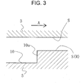
- the individual dimples 10 can be considered to constitute a Rayleigh step as shown in FIG. 3 .
- a Rayleigh step 10a extending in a direction orthogonal to a cross section of the figure is formed on the sliding face S(R) of the stationary-side seal ring 5, and the sliding face S of the rotating-side seal ring 3 is flattened.
- dynamic pressure positive pressure
- the lubricating liquid film between the sliding faces is increased, improving lubrication performance.
- FIG. 4 is an enlarged plan view of a part of the sliding face S of the stationary-side seal ring 5 shown in FIG. 2A .
- the plurality of dimples 10 formed on the sliding face is provided independently of each other, and is disposed such that the plurality of circular dimples of substantially the same opening diameter is distributed randomly.
- the plurality of circular dimples 10 is of substantially the same opening diameter, and is provided independently of each other.
- the ratio between the depth h and the diameter D of the dimples is preferably set in a range of 1/500 to 1/10 in terms of improving the sliding characteristics in a wide range of bearing characteristic numbers at the sliding face.
- the ratio between the depth h and the diameter D of the dimples is in a range of 1/400 to 1/20, and more preferably, the ratio between the depth h and the diameter D of the dimples is in a range of 1/240 to 1/60.
- the dimples shown in FIG. 4 are set to about 0.5 ⁇ m in depth h, and about 100 ⁇ m in opening diameter D. In this case, the ratio between the depth h and the opening diameter D of the dimples is 1/200.
- about 0.5 ⁇ m refers to one within a range of 0.5 ⁇ 10% ⁇ m
- about 100 ⁇ m refers to one within a range of 100 ⁇ 10% ⁇ m.
- the opening diameter D of the dimples is a mean value of a "largest-diameter portion" and a "smallest-diameter portion” along a boundary line between an unworked surface and a worked surface.
- a position in which its shape changes in the depth direction by 0.05 ⁇ m or more except the surface roughness of the sliding face S, or a position in which its shape changes in the depth direction by 1/10 or more of the depth of the deepest portion of the dimple except the surface roughness of the sliding face S is taken as a boundary between an unworked surface and a worked surface.
- Substantially the same opening diameter D means one within a range of ⁇ 10% of a design value of the opening diameter.
- Equivalent diameter 4 ⁇ dimple cross-sectional area / dimple circumferential length
- a cross-sectional shape of a dimple 10 is a shape as shown in FIG. 5
- a mean position within a range of D/4 from the center of a worked surface is calculated, and a height dimension from the calculated position to an unworked surface is taken as the depth h of the dimple 10.
- the plurality of circular dimples 10 of substantially the same opening diameter is arranged to be randomly distributed in the circumferential and radial directions of the sliding face S, and is set such that the area ratio of the dimples 10 within a 120° unit angle in a circumferential direction of the sliding face S (the sum of the areas of all the dimples/the area of the sliding face) is in a range of 8% to 50%.
- the area ratio of the dimples 10 is set to a proper value depending on the sealing pressure of the sliding face S.
- the area ratio is desirably set by performing a rotation test on the sliding part based on a sealing pressure, and checking the leakage rate under the sealing pressure.
- the area ratio of the dimples 10 needs to be set depending on the material of the sliding part. For example, when the material is porous SiC, an area ratio of the dimples 10 of about 8% is proper because if it is 10% or more, pores can be continuously connected to each other.
- FIG. 6 is a reference diagram showing the relationship between a friction coefficient and a bearing characteristic number G which are obtained by a rotational sliding test.
- a body portion of the testing machine 19 includes a casing 13 that supports a stationary ring 11 in a non-rotating state via a spring 12, a rotating shaft 14 rotatably extending through the inner periphery of the casing 13, and a rotating ring 15 that is supported on the outer periphery of the rotating shaft 14 and axially oppose the stationary ring 11.
- a sealed liquid L is sealed in a sealed space enclosed by the rotating ring 15, the casing 13, and the rotating shaft 14, a sealed liquid L is sealed.
- the testing machine 19 is characterized in that hydrostatic gas bearings are used as bearing portions 16 on opposite sides to allow precise measurement of the sliding torque of the mechanical seal.
- the torque is measured in two ways, a torque meter 17 and a cantilever-type load cell 18, to eliminate measurement errors by double-checking.
- the sliding component according to the embodiment of the present invention achieves the following especially outstanding effects.
- the embodiment has described the case where a sliding part is used as at least one of a pair of rotating and stationary seal rings in a mechanical seal device.
- the present invention can also be used as a bearing sliding part that slides on a rotating shaft while sealing lubricating oil on one axial side of a cylindrical sliding face.
- the embodiment has described the case where a high-pressure sealed fluid is present on the outer-peripheral side.
- the present invention is also applicable to the case where a high-pressure fluid is on the inner-peripheral side.
- dimples may be arranged to communicate with the inner-peripheral side.
- the embodiment has described the case where a plurality of dimples is about 0.5 ⁇ m in depth h and about 100 ⁇ m in opening diameter D. These show one preferable example, and are not limiting.
- the ratio between the depth h and the diameter D of dimples only needs to be set in a range of 1/500 to 1/10.
- the embodiment has described the case where 40% is selected as the area ratio of a plurality of dimples within a 120° unit angle in a circumferential direction of a sliding face, in terms of achieving both sealing and lubrication.
- 40% is selected as the area ratio of a plurality of dimples within a 120° unit angle in a circumferential direction of a sliding face, in terms of achieving both sealing and lubrication.
- the area ratio of dimples within a 120° unit angle in a circumferential direction of a sliding face only needs to be in a range of 30% to 50%.
Landscapes
- Engineering & Computer Science (AREA)
- General Engineering & Computer Science (AREA)
- Mechanical Engineering (AREA)
- Chemical & Material Sciences (AREA)
- Oil, Petroleum & Natural Gas (AREA)
- Mechanical Sealing (AREA)
- Sliding-Contact Bearings (AREA)
Applications Claiming Priority (2)
| Application Number | Priority Date | Filing Date | Title |
|---|---|---|---|
| JP2016171322 | 2016-09-01 | ||
| PCT/JP2017/030432 WO2018043307A1 (ja) | 2016-09-01 | 2017-08-25 | しゅう動部品 |
Publications (2)
| Publication Number | Publication Date |
|---|---|
| EP3508763A1 true EP3508763A1 (de) | 2019-07-10 |
| EP3508763A4 EP3508763A4 (de) | 2020-04-15 |
Family
ID=61300948
Family Applications (1)
| Application Number | Title | Priority Date | Filing Date |
|---|---|---|---|
| EP17846312.1A Withdrawn EP3508763A4 (de) | 2016-09-01 | 2017-08-25 | Gleitkomponente |
Country Status (6)
| Country | Link |
|---|---|
| US (1) | US20190170257A1 (de) |
| EP (1) | EP3508763A4 (de) |
| JP (1) | JPWO2018043307A1 (de) |
| CN (1) | CN109563935A (de) |
| AU (1) | AU2017318903A1 (de) |
| WO (1) | WO2018043307A1 (de) |
Families Citing this family (13)
| Publication number | Priority date | Publication date | Assignee | Title |
|---|---|---|---|---|
| CN109563934A (zh) | 2016-08-15 | 2019-04-02 | 伊格尔工业股份有限公司 | 滑动部件 |
| KR102346395B1 (ko) | 2017-05-19 | 2022-01-03 | 이구루코교 가부시기가이샤 | 슬라이딩 부품 |
| CN110621923B (zh) | 2017-05-19 | 2021-07-02 | 伊格尔工业股份有限公司 | 滑动部件 |
| KR102459648B1 (ko) | 2017-07-14 | 2022-10-28 | 이구루코교 가부시기가이샤 | 슬라이딩 부품 |
| CN111148926A (zh) * | 2017-10-03 | 2020-05-12 | 伊格尔工业股份有限公司 | 滑动部件 |
| KR102407098B1 (ko) | 2018-01-12 | 2022-06-10 | 이구루코교 가부시기가이샤 | 슬라이딩 부품 |
| WO2019151396A1 (ja) * | 2018-02-01 | 2019-08-08 | イーグル工業株式会社 | 摺動部品 |
| WO2019202911A1 (ja) * | 2018-04-18 | 2019-10-24 | 兼房株式会社 | ディンプル付き被加工物及びディンプル加工方法 |
| EP3922874A4 (de) | 2019-02-04 | 2022-11-09 | Eagle Industry Co., Ltd. | Gleitkomponente |
| EP3922877B1 (de) | 2019-02-04 | 2023-12-06 | Eagle Industry Co., Ltd. | Gleitkomponenten und verfahren zur herstellung einer gleitkomponente |
| JP7404352B2 (ja) * | 2019-04-11 | 2023-12-25 | イーグル工業株式会社 | 摺動部品 |
| KR20230022986A (ko) | 2020-07-06 | 2023-02-16 | 이구루코교 가부시기가이샤 | 슬라이딩 부품 |
| JPWO2022009771A1 (de) | 2020-07-06 | 2022-01-13 |
Family Cites Families (12)
| Publication number | Priority date | Publication date | Assignee | Title |
|---|---|---|---|---|
| JPH01158853U (de) * | 1988-03-18 | 1989-11-02 | ||
| JPH11287329A (ja) | 1998-04-03 | 1999-10-19 | Eagle Ind Co Ltd | 摺動材 |
| JP2000169266A (ja) | 1998-12-04 | 2000-06-20 | Eagle Ind Co Ltd | 摺動材 |
| US6341782B1 (en) * | 2000-03-03 | 2002-01-29 | Surface Technologies Ltd | Lubricated seals having micropores |
| JP4205910B2 (ja) * | 2002-04-02 | 2009-01-07 | イーグル工業株式会社 | 摺動部品 |
| JP2005249150A (ja) * | 2004-03-08 | 2005-09-15 | Daido Metal Co Ltd | 摺動部材、その製造方法および製造装置 |
| WO2008013147A1 (fr) * | 2006-07-25 | 2008-01-31 | Eagle Industry Co., Ltd. | Dispositif d'etanchéité mécanique |
| EP2686587B1 (de) * | 2011-03-15 | 2018-09-05 | Flowserve Management Company | Makro-/mikro-funktionalität mit konischem kanal für mechanische gleitringdichtungen |
| CN103635705B (zh) * | 2011-07-01 | 2017-03-01 | 松下电器产业株式会社 | 滑动部件 |
| CN107269846B (zh) * | 2013-09-18 | 2020-01-21 | 伊格尔工业股份有限公司 | 滑动部件 |
| JP6683630B2 (ja) * | 2015-02-14 | 2020-04-22 | イーグル工業株式会社 | しゅう動部品 |
| CN105299233A (zh) * | 2015-11-20 | 2016-02-03 | 湖南天雁机械有限责任公司 | 经过激光表面织构的涡轮增压器密封环及加工方法 |
-
2017
- 2017-08-25 EP EP17846312.1A patent/EP3508763A4/de not_active Withdrawn
- 2017-08-25 JP JP2018537213A patent/JPWO2018043307A1/ja active Pending
- 2017-08-25 WO PCT/JP2017/030432 patent/WO2018043307A1/ja unknown
- 2017-08-25 CN CN201780050014.6A patent/CN109563935A/zh active Pending
- 2017-08-25 AU AU2017318903A patent/AU2017318903A1/en not_active Abandoned
- 2017-08-25 US US16/322,302 patent/US20190170257A1/en not_active Abandoned
Also Published As
| Publication number | Publication date |
|---|---|
| CN109563935A (zh) | 2019-04-02 |
| WO2018043307A1 (ja) | 2018-03-08 |
| AU2017318903A1 (en) | 2019-03-07 |
| JPWO2018043307A1 (ja) | 2019-07-11 |
| US20190170257A1 (en) | 2019-06-06 |
| EP3508763A4 (de) | 2020-04-15 |
Similar Documents
| Publication | Publication Date | Title |
|---|---|---|
| EP3508763A1 (de) | Gleitkomponente | |
| JP6800089B2 (ja) | しゅう動部品の製造方法 | |
| EP3258145B1 (de) | Gleitkomponente | |
| JP6076971B2 (ja) | 摺動部品 | |
| JP2004003578A (ja) | 摺動部品 | |
| US11035411B2 (en) | Sliding parts | |
| EP3627011B1 (de) | Gleitkomponente | |
| US9970478B2 (en) | Sliding parts | |
| JP7275028B2 (ja) | 摺動部品 |
Legal Events
| Date | Code | Title | Description |
|---|---|---|---|
| STAA | Information on the status of an ep patent application or granted ep patent |
Free format text: STATUS: THE INTERNATIONAL PUBLICATION HAS BEEN MADE |
|
| PUAI | Public reference made under article 153(3) epc to a published international application that has entered the european phase |
Free format text: ORIGINAL CODE: 0009012 |
|
| STAA | Information on the status of an ep patent application or granted ep patent |
Free format text: STATUS: REQUEST FOR EXAMINATION WAS MADE |
|
| 17P | Request for examination filed |
Effective date: 20190226 |
|
| AK | Designated contracting states |
Kind code of ref document: A1 Designated state(s): AL AT BE BG CH CY CZ DE DK EE ES FI FR GB GR HR HU IE IS IT LI LT LU LV MC MK MT NL NO PL PT RO RS SE SI SK SM TR |
|
| AX | Request for extension of the european patent |
Extension state: BA ME |
|
| DAV | Request for validation of the european patent (deleted) | ||
| DAX | Request for extension of the european patent (deleted) | ||
| A4 | Supplementary search report drawn up and despatched |
Effective date: 20200318 |
|
| RIC1 | Information provided on ipc code assigned before grant |
Ipc: F16C 33/10 20060101ALI20200312BHEP Ipc: F16C 17/04 20060101ALI20200312BHEP Ipc: F16J 15/34 20060101AFI20200312BHEP Ipc: F16C 33/22 20060101ALI20200312BHEP |
|
| STAA | Information on the status of an ep patent application or granted ep patent |
Free format text: STATUS: THE APPLICATION IS DEEMED TO BE WITHDRAWN |
|
| 18D | Application deemed to be withdrawn |
Effective date: 20201020 |